Majorcom: PX-6120 User manual

Manual to download in PDF format on www.majorcom.fr
PX-6120
USER
MANUAL
6*6 ZONES MATRIX AMPLIFIER
WITH MP3/FM/BLUETOOTH PLAYER

56, chemin de la Flambère • 31300 Toulouse • FRANCE • Tél. 33 (0)5 61 31 86 87
2
56, chemin de la Flambère • 31300 Toulouse • FRANCE • Tél. 33 (0)5 61 31 86 87
3
PX-6120 6*6 ZONES MATRIX AMPLIFIER WITH MP3/FM/BT PLAYER
Caution : Please read this manual carefully before using it. Damage caused by misuse is not covered by the
warranty.
1. Read and keep these instructions
2. Heed all warnings and follow all instructions.
3. Do not use this device near water.
4. Do not block ventilation openings. Install the device according to the manufacturer’s instructions.
5. Do not install the appliance near heat sources such as radiators, heat vents, stoves or any other heat-producing ap-
pliances.
6. Donot neglect the safety objective of the polarized plug or grounding plug. A polarized plug has two blades, one being
wider than the other. A grounding plug has two blades and a third grounding pin. The wide blade or third pin is provided for
your safety. If the plug provided does not t your outlet, consult an electrician for the replacement of the obsolete outlet.
7. Protect the power cord so that it is not trampled or pinched, especially at the plugs, power outlets and where it comes out
of the device
8. Use only accessories specied by the manufacturer.
9. Use only the cart, stand, tripod, console or table specied by the manufacturer or sold with the device. When using a
trolley, be careful when moving the trolley/appliance assembly to avoid injury due to tipping.
10. Unplug this device during thunderstorms or when not in use for long periods of time
11. Entrust all repairs to qualied personnel. Maintenance is required when the device has been damaged in any way, such
as when the power cord or plug is damaged, when a liquid has been spilled or objects have fallen into the device, when the
device has been exposed to rain or moisture, when it is not working normally or when it has fallen
12. This device should not be exposed to drops of water or splashes and no liquid-lled objects, such as a vase, should be
placed on the device
13. Plug this device into the appropriate wall outlet and make the plug to be unplugged easily usable.
14. The main plug shall be used as a disconnection device and shall remain easily usable during the intended use. In order
to completely disconnect the device from the mains, the mains plug must be completely disconnected from the power outlet
15. WARNING: To reduce the risk of re or electric shock, do not expose this device to rain or moisture.
16. An appliance with a protective ground terminal must be connected to a power outlet with a protective ground connection.
SUMMARY
1. SAFETY WARNINGS
1. SAFETY WARNINGS...................................................................................................................p. 3
2. INTRODUCTION........................................................................................................................... p.4
2.1 DESCRIPTION GÉNÉRALE...........................................................................................p.4
2.2 FRONT PANEL.................................................................................................................p.5
2.3 BACK PANEL....................................................................................................................p.6
3. USER GUIDE.................................................................................................................................p.6
3.1 CONNECTION AND CONFIGURATION........................................................................p.6
3.2 DIP SWITCHES............................................................................................................... p.7
3.3 ACTIVATION OF PRIORITIES AND EMERGENCIES................................................. p.7
3.4 SIGNAL INPUTS AND OUTPUTS..................................................................................p.7
3.5 SPEAKER OUTPUTS......................................................................................................p.8
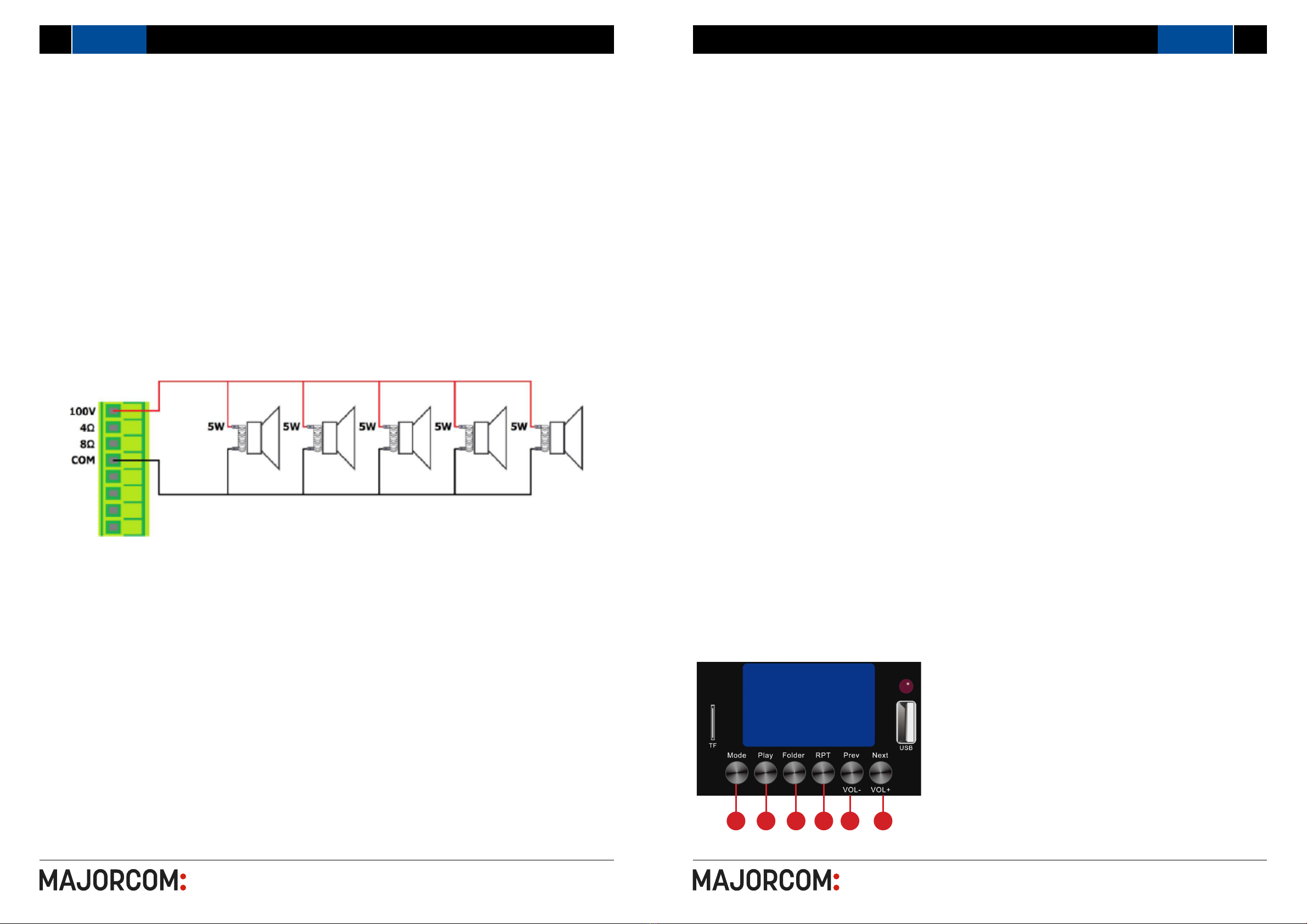
3.6 100V LINE SYSTEMS......................................................................................................p.8
3.7 LOW IMPEDANCE SYSTEMS........................................................................................p.8
3.8 MEANING OF LED DISPLAY..........................................................................................p.9
3.9 OPERATION.....................................................................................................................p.9
3.10 EMBEDDED MULTI-SOURCE AUDIO PLAYER..........................................................p.9
3.11 BLUETOOTH OPERATION.........................................................................................p.10
3.12 TUNER FM....................................................................................................................p.10
3.13 USB/SD DRIVE............................................................................................................p.10
4. APPLICATION..............................................................................................................................p.11
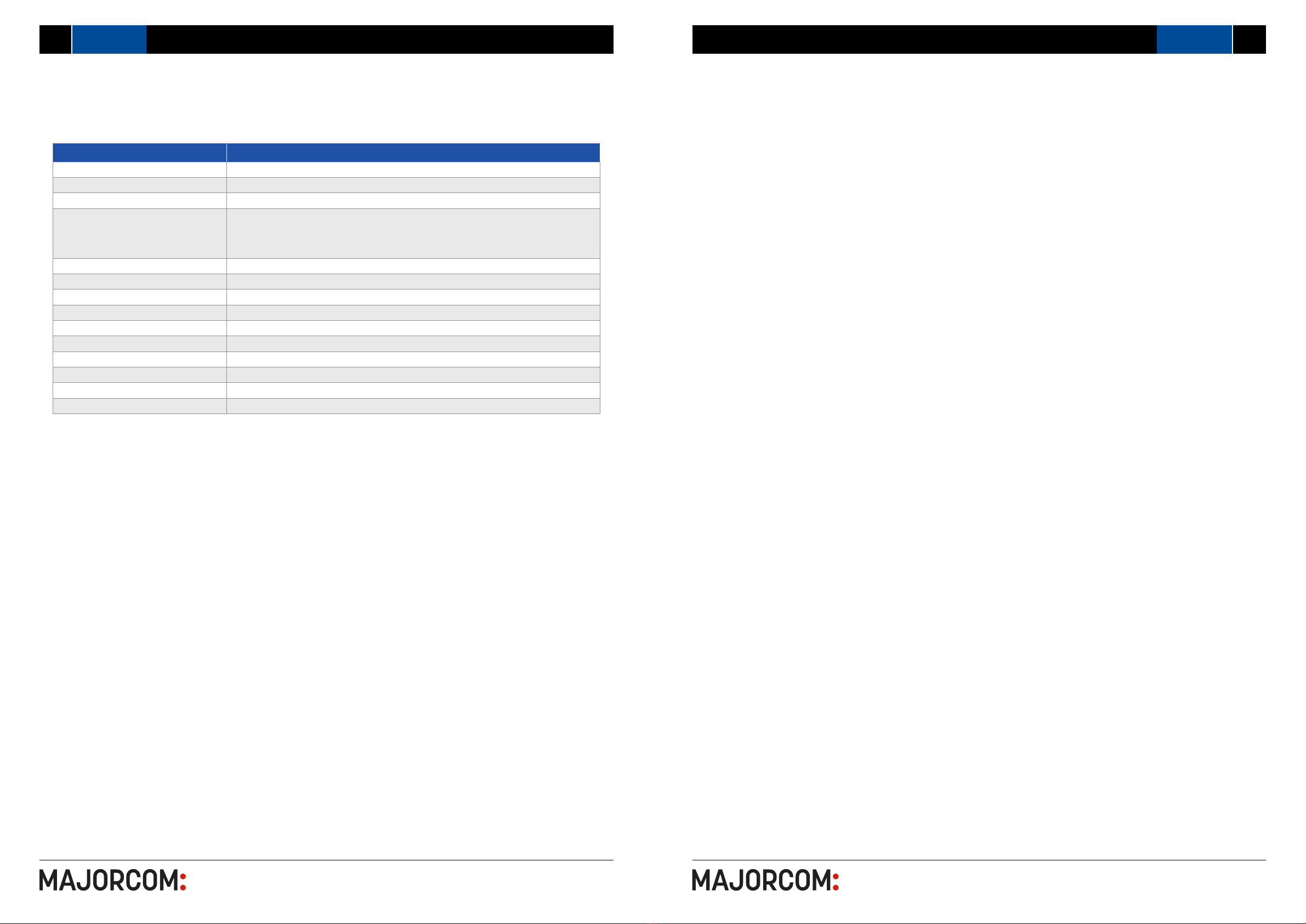
5. TECHNICAL CHARACTERISTICS............................................................................................p.12
6*6 ZONES MATRIX AMPLIFIER WITH MP3/FM/BT PLAYER PX-6120
User manual Manuel d’utilisation
TO PREVENT FIRE OR SHOCK HAZARD, DO NOT USE THE PLUG WITH AN EXTENSION CORD, RECEPTACLE OR
OTHER OUTLET UNLESS THE BLADES CAN BE FULLY INSERTED TO PREVENT BLADE EXPOSURE.
TO REDUCE THE RISK OF FIRE OR ELECTRIC SHOCK, DO NOT EXPOSE THIS APPLIANCE TO RAIN OR MOISTURE.
TO PREVENT ELECTRICAL SHOCK, MATCH WIDE BLADE PLUG TO WIDE SLOT, FULLY INSERT.
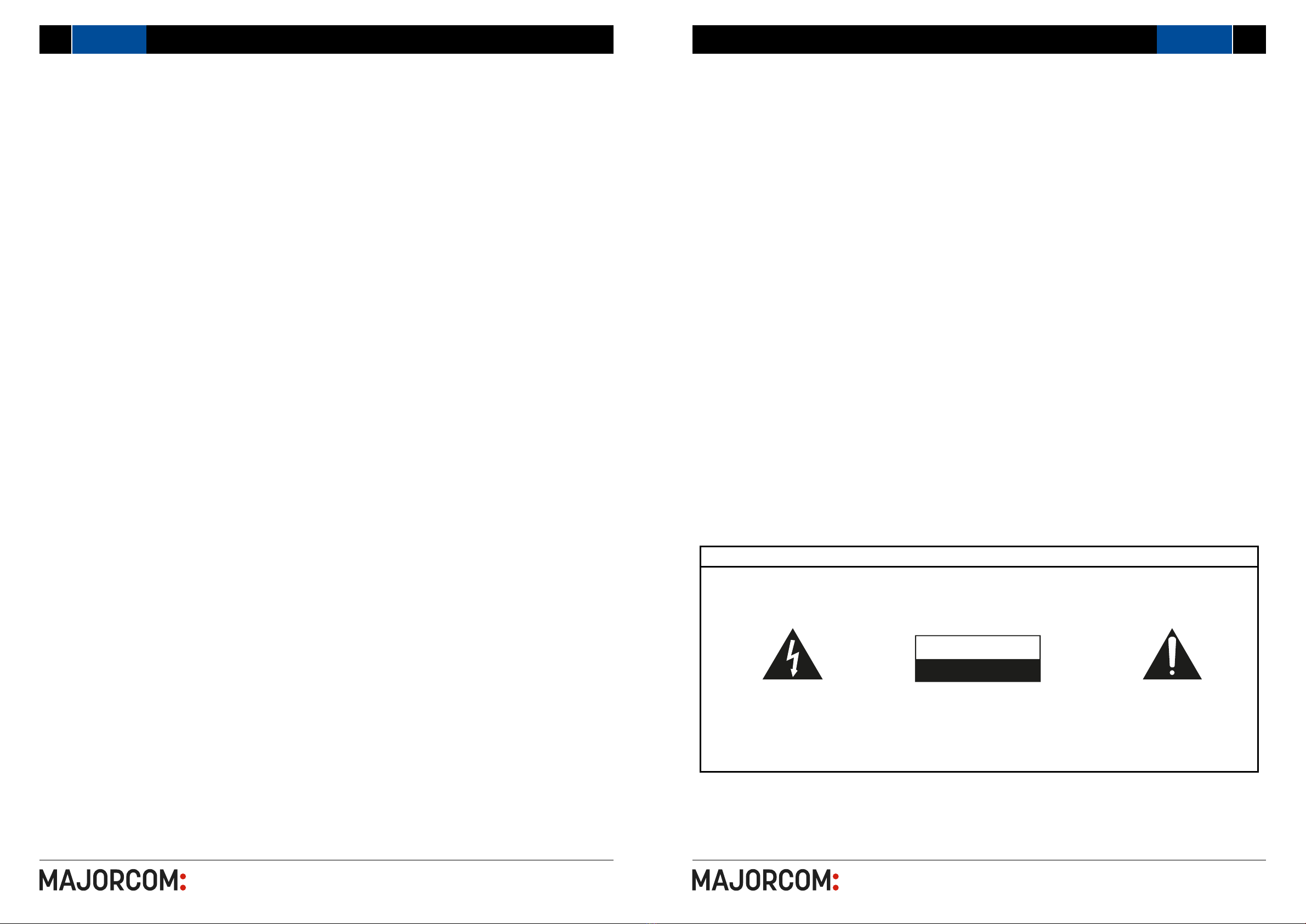
CAREFUL !
The exclamation point within an
equilateral triangle is intended to alert
the user to the presence of important
operating and maintenance
(servicing) instructions in the literature
accompanying the appliance.
The lightning ash with arrowhead
symbol within an equilateral triangle
is intended to alert the user to
the presence of uninsulated «dangerous
voltage» within the product’s enclosure that
may be of sucient magnitude to constitute
a risk of electric shock to persons.
WARNING : TO REDUCE THE RISK OF
ELECTRIC SHOCK, DO NOT REMOVE
COVER (OR BACK). NO USER SERVICEABLE
PARTS INSIDE. REFER SERVICING TO
QUALIFIED SERVICE PERSONNEL.
RISK OF ELECTRIC SHOCK
DO NOT OPEN
CAUTION

56, chemin de la Flambère • 31300 Toulouse • FRANCE • Tél. 33 (0)5 61 31 86 87
4PX-6120
56, chemin de la Flambère • 31300 Toulouse • FRANCE • Tél. 33 (0)5 61 31 86 87
5
PX-6120
• 6×6 matrix mixer amplier with 6 x 120W outputs.
• 5 sources and one EMC priority input distributed across 6 zones.
• MP3/FM/Bluetooth player, 3 mic/line, auxiliary input, and EMC priority input.
• 6-channel mixer amplier controller with audio sources, zone volume control.
• Matrix amplier withLatin p of volume and selective microphone panel.
• 6 RJ45 connections by CAT5/6 cable up to 200 meters for Latin pvolume and selective mi-
crophone panel.
• 6 selective call microphones can be connected by CAT5 cable up to 200 meters of communi-
cation.
• 6 areas of dierent music programs and dierent output volumes.
• 6 speaker outputs of 100V or 4/8 Ohms.
• 3 switchable micro/line inputs on balanced XLR with 48V phantom power supply, Mic1/Mic2/
Mic3 with chime functions (modiable in mp3).
• 1 auxiliary input and a built-in USB/SD/FM and Bluetooth drive can be switched by matrix to
one of the 6 zones independently.
• Each microphone input has a switchable phantom power supply.
• Priority: LM-6000>M-6000>Mic1/Mic2/Mic3 Trigger>EMC>.
• Selective announcement microphone 6 zones.
• Designed for all-in-one use that requires dierent audio sources.
• USB/SD/FM audio player and built-in remote control.
• Internal Bluetooth receiver for mobile use.
• Operation in 100V or 4/8 Ohms for sound systems.
• 6 independent exit zones for the sound system of several zones.
• Coupure sound system by triggering 24VDC from a re alarm system.
• Operating system in 230VAC.
(1) Mp3/FM/Bluetooth media player module
(2) Micro-SD card slot.
(3) Function button
(4) IR receiver
(5) Location for MP3
(6) Area Selector for MP3: You can choose to
route and play MP3 in any area
(7) Zone selector for Mic1/Line1: You can route
MIC1/Line2 in any zone
(8) Zone Selector for Mic2/Line2: You can route
MIC1/Line2 in any zone
(9) Zone selector for Mic3/Line3: You can route
Mic3/Line3 in any zone
(10) AUX input selector you can route this input
to any zone
(11) Zone View: Indicates the source being
broadcast in the zone
(12) MON: Monitoring open or closed
(13) Control of the volume of the zone
(14) Controlling the Volume of the Audio Input
(15) Output monitoring on jack 6.35mm
(16) Volume control for monitoring
(17) Carillon
(18) Volume control for the chime
(19) Indication of feeding
(20) Power switch
2. INTRODUCTION
2.1 DESCRIPTION GÉNÉRALE
2.2 FRONT PANEL
Manuel d’utilisation
321 6 7 8 9 10 11 20
19
1516
1718
14
12 13
5
4
User manual
6*6 ZONES MATRIX AMPLIFIER WITH MP3/FM/BT PLAYER 6*6 ZONES MATRIX AMPLIFIER WITH MP3/FM/BT PLAYER

56, chemin de la Flambère • 31300 Toulouse • FRANCE • Tél. 33 (0)5 61 31 86 87
6PX-6120
56, chemin de la Flambère • 31300 Toulouse • FRANCE • Tél. 33 (0)5 61 31 86 87
7
PX-6120
(21) AC power outlet
(22) Zone Output-100V & 8Ω
(23) Booster output of the 6 zones
(24) Release monitoring in CAR
(25) EMC Entry (Priority Entry Type ARM-911A)
(26) Entrance AUX
(27) Mic 1/Line 1 input
(28) Mic 2/Line 2 input
(29) Bass and treble control
(30) Mic 3/Line 3 input.
(31) RJ45 interface for microphone panel and vo-
lume deck.
(32) FM antenna
(33) 24VDC input to trigger the reading of a
message or sound cut
2.3 BACK PANEL
Manuel d’utilisation
With the P X-6120 powered o (20), connect the rear IEC jack (21) to the MAINS using the supplied AC
cable (or equivalent approved type). Verify that the voltage is correct and that the speaker connection is
correct, then turn on the device.
The P x-6120 has 5 input channels and a built-in multi-source audio player.
Mic inputs 1, 2 and 3 are designed to receive microphones or line-level sources (such as a CD/mp3 player
or the output of a mixer) via combo connectors on the back panel, they are switchable by DIP switch.
They can accept XLR or 6.35mm jack plugs for balanced or unbalanced signals.
3. USER GUIDE
3.1 CONNECTION AND CONFIGURATION
3.2 DIP SWITCHES
3.4 SIGNAL INPUTS AND OUTPUTS
Connect microphones or line signals to Mic/Line 1, 2 and 3 inputs (27, 28, 30) using good quality audio
cables. A stereo or mono line level source can be connected to the input of auxiliary channel 4 on 2 RCA
connectors (26).
To check the output of any area, an assignable Monitor output can be connected to headphones from the
6.35mm jack on the front panel (15).
(15) or as a line output (e.g. to active speakers) from the RCA connectors on the back (24).
Each zone output has a dedicated RCA signal output on the back panel (23), which can be connected to
the line inputs of active speakers or booster ampliers. These outputs are in addition to the speaker out-
puts detailed below.
An antenna input (32) is provided on the back panel for connection to an external antenna for FM tuning
There are bass and treble controls on the back panel to adjust the sound of the MIC and Line input signal.
Mic/line inputs 1, 2 and 3 each have 2 DIP switches on the back panel to adjust the input level and/or en-
able the +20V phantom power supply for the use of condenser microphones.
Set the level correctly for the type of input source connected (microphone or line).
If the connected source is a condenser microphone that requires phantom power, make sure phantom is
enabled for that channel.
Be sure to make these DIP switch settings when the amplier is turned o.
1. MESSAGE (HORN) - trigger on 24VDC, the message is activated (or sound cut)
2. EMC input - emergency priority audio input
3. RM-6000 Microphone Panel
4. Other local entry
3.3 ACTIVATION OF PRIORITIES AND EMERGENCIES
21 22 23 3331302827
3229
2625
24
User manual
6*6 ZONES MATRIX AMPLIFIER WITH MP3/FM/BT PLAYER 6*6 ZONES MATRIX AMPLIFIER WITH MP3/FM/BT PLAYER

56, chemin de la Flambère • 31300 Toulouse • FRANCE • Tél. 33 (0)5 61 31 86 87
8PX-6120
56, chemin de la Flambère • 31300 Toulouse • FRANCE • Tél. 33 (0)5 61 31 86 87
9
PX-6120
The P X-6120 has an independent output for each zone, connected via 3 large plugs with modular
terminals. Each plug can be removed from the back panel for convenient connection of the speaker out-
puts.
Each zone output can be used to power either 100V line speakers or standard low impedance speakers.
These two congurations cannot be used together, so it is important to decide which one will be used initially.
A 100V line speaker system can include many speakers connected together. The determining factor in
knowing how many speakers can be used on a single amplier is the rated power. In most cases, it is
advisable to connect as many speakers as necessary with a combined power not exceeding 80% of the
rated output power of the amplier (in the case of the PX-6120, this represents 120W per output area).
• C0 : RM-6000
• C1 : MP3 Module
• C2 : MIC1/Line1
• C3 : MIC2/Ligne2
• C4 : MIC3/Line3
• C5 : TO
• C6 : EMC
• C7 : Local Entrance
• C8 : Horn 24VDC control
Manuel d’utilisation
3.8 MEANING OF LED DISPLAY
3.10 EMBEDDED MULTI-SOURCE AUDIO PLAYER
The P X-6120 is equipped with a built-in audio player, controlled by a backlit LCD screen and carrying
buttons. This section provides access to a Bluetooth™ receiver, an FM radio tuner and a USB/SD audio
player.
In order to stream audio in one of the areas, it is necessary to press one of the «Play» buttons (4).
3.9 OPERATION
Once all connections to the amplier have been made, lower all rotating controls and turn on the device;
the power LED lights up.
To verify that the system is working properly, select an input source and output area to test. In the following
example, the Mic/Line 1 input and the Zone 1 output were selected.
• Press the Z1 button on the line of MIC/Line1, if zone 1 displays C2, it means that the output MIC/Line1
is routed to zone 1.
• If you want to play your MP3s, press the Z1 button on the MP3 line, zone 1 will receive MP3 music and
the screen in zone 1 will show C1
If zone 1 cannot be heard from the location of the P X-6120, use the monitoring function as follows :
• Press the Monitor button (12) and connect a headset to the Monitor output (15).
• Make sure the Monitor button for Mic/Line 1 is pressed and listen to the headphones Gradually increase
the monitor level control and check the output to zone 1.
3.5 SPEAKER OUTPUTS
3.7 LOW IMPEDANCE SYSTEMS
Alternatively, each zone output is capable of powering one or more low-impedance speakers. There is an
option on each zone for a 4Ω or 8Ω speaker output to determine the minimum impedance. It is essential
to select the right output terminal when opting for low-impedance speakers.
For a single 8Ω speaker, connect the positive wire (+) to the terminal «8Ω» and the negative wire (-) to
«COM» For a single 4Ω speaker or for 2 8Ω speakers connected in parallel, connect the positive wire (+)
to the terminal «4Ω» and the negative wire (-) to «COM».
In both cases, the connected load must have a combined impedance not lower than that indicated on the
terminal. Lower impedance can cause irreparable damage to the amplier.
The connected speaker(s) must also have a power capacity to accept up to 120 Wrms from the exit of the
zone. A lower rated power may damage the speakers.
For 100 V speakers, connect the output of the selected area to the rst speaker in the zone using a
dual-insulation speaker wire with sucient rated current to support the full output of the amplier.
Connect the output terminal «100V» of the selected area to the positive connection (+) of the speaker
and the output «COM» to the negative connection (-) of the speaker. Connect other speakers in parallel
with the rst speaker, with all positive terminals connected together and all negative terminals connected
together, as shown below.
3.6 100V LINE SYSTEMS
(3) Mode : Choose between Bluetooth, FM, USB playback or SD
(4) Play : Music playback
(5) Folder : Music folder
(6) RPT : Repeat
(7) Prev : Back (quick press)
(8) Next : Next title (quick press)
(7) Vol+ : Increase volume (long press)
(8) Vol- : Decrease the volume (long press)
3 4 5 6 7 8
User manual
6*6 ZONES MATRIX AMPLIFIER WITH MP3/FM/BT PLAYER 6*6 ZONES MATRIX AMPLIFIER WITH MP3/FM/BT PLAYER

56, chemin de la Flambère • 31300 Toulouse • FRANCE • Tél. 33 (0)5 61 31 86 87
10 PX-6120
56, chemin de la Flambère • 31300 Toulouse • FRANCE • Tél. 33 (0)5 61 31 86 87
11
PX-6120
3.11 BLUETOOTH OPERATION
3.12 TUNER FM
3.13 USB/SD DRIVE
4. APPLICATION
Manuel d’utilisationUser manual
6*6 ZONES MATRIX AMPLIFIER WITH MP3/FM/BT PLAYER 6*6 ZONES MATRIX AMPLIFIER WITH MP3/FM/BT PLAYER
The X-6120 P audio player has inputs for a USB ash drive or micro-SD card containing standard com-
pressed digital audio les. Inserting one or both of these cards will allow the reader to read these sources
and the screen will display «MP3 Mode».
After inserting the USB drive, the playback is automatic, you can use «Prev» or «NEXT» to choose the last
or next song, «REPT» to repeat one or all the songs.
Press the «Mode» button to switch to the FM tuner function. For good FM reception, it will be necessary to
connect an external antenna (AFM from MAJRCOM) to the Antenna connector on the back panel using a
good quality RF coaxial cable.
If no channels are tuned in, press the «Play» button to start auto-tune, which scans available stations
and stores them as stations in the P X-6120’s FM tuner. To switch between stations, press the «Prev» or
«NEXT» buttons.
In order to be able to play the sound of a smartphone, tablet or other Bluetooth device, the built-in Bluetooth
receiver must be paired with a device within the range.
To pair a device with the Bluetooth P X-6120 receiver, it is necessary to search for the devices in the
Bluetooth menu of the transmitter device and select the pairing with «ULISSE», password: 1234. Once
paired, the screen of the P X-6120 will indicate that it is connected.
Select to connect as an audio device and play the audio tracks on the smartphone or tablet (or other) and
the audio should be heard on the selected area.
The buttons labeled «Prev» and «Next» are used to adjust the output volume of the audio player.
Press and hold «Prev» to increase the volume or press and hold «Next» to decrease the volume.
If the transmitting device is out of range or if the audio player mode is changed, the connection stops.
Returning to the range area or Bluetooth mode will restore pairing.
It may be necessary to reselect the connection as an audio device on the sending device.

56, chemin de la Flambère • 31300 Toulouse • FRANCE • Tél. 33 (0)5 61 31 86 87
12 PX-6120
5. TECHNICAL CHARACTERISTICS
MODEL
PX-6120
Zones 6
Output power 6 x 120 W
Speaker output 100 V and 4/8 Ω
Inputs
Mic/Line 1-3 : 2,5 mV, balanced XLR input with 48 V phantom power supply
Line 1-2 : 250 mV, RCA
Mute : 250 mV, Bornier Phoenix
Remote microphone Up to 6 RM-6000 per matrix
Volume/source wall plate Up to 6 LM-6000 per matrix
Bandwidth 80 Hz - 16 000 Hz
THD < 0,1 %
S/N > 70 dB
Protection Protection against high temperatures, short circuits and overloads
Power 230 V AC or 110 V AC, 50-60 Hz
Consumption 900 W
Dimensions (LxHxP) 484 x 88 x 320 mm
Weight 15,5 Kg
56, chemin de la Flambère • 31300 Toulouse • FRANCE • Tél. 33 (0)5 61 31 86 87
13
Manuel d’utilisation
PX-6120
NOTES
User manual
6*6 ZONES MATRIX AMPLIFIER WITH MP3/FM/BT PLAYER 6*6 ZONES MATRIX AMPLIFIER WITH MP3/FM/BT PLAYER

56, chemin de la Flambère • 31300 Toulouse • FRANCE • Tél. 33 (0)5 61 31 86 87
User manual
PX-6120
AMPLIFICATEUR MATRICIEL 6*6 ZONES
AVEC LECTEUR MP3/FM/BLUETOOTH
Table of contents
Other Majorcom: Amplifier manuals

Majorcom:
Majorcom: PX-4120 User manual

Majorcom:
Majorcom: MX-60 User manual

Majorcom:
Majorcom: PM-839 User manual

Majorcom:
Majorcom: digiPRO 1200 User manual

Majorcom:
Majorcom: DPS-240S User manual

Majorcom:
Majorcom: MX-3120MM User manual

Majorcom:
Majorcom: AP 30 User manual

Majorcom:
Majorcom: PA120 User manual

Majorcom:
Majorcom: PA COM 13X5 User manual