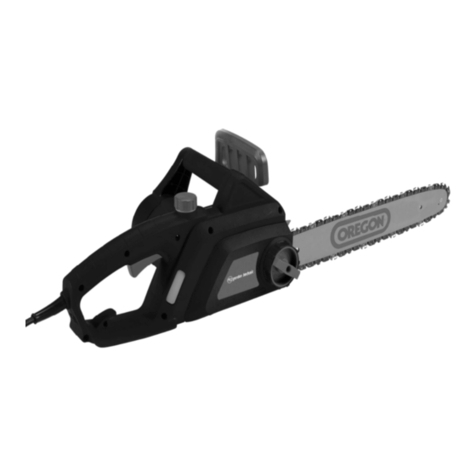
Makita DUC302RF2 User manual

DUC252
DUC302
EN Cordless Chain Saw INSTRUCTION MANUAL 7
RU Цепная пила с питанием от
аккумуляторной батареи
РУКОВОДСТВО ПО
ЭКСПЛУАТАЦИИ 19
KK
Аккумуляторлы
батареядан қуаттанатын
шынжырлы ара
ПАЙДАЛАНУ ЖӨНІНДЕГІ
НҰСҚАУЛЫҚ 33

12
3
1
1
1
2
1
2
1
23
1
Fig.1
Fig.2
Fig.3
Fig.4
Fig.5
Fig.6
Fig.7
Fig.8
2

2
1
1
1
1
1
2
2
1
2
1
Fig.9
Fig.10
Fig.11
Fig.12
Fig.13
Fig.14
Fig.15
Fig.16
3

12
345
2
1
1
3
2
1
1
2
Fig.17
Fig.18
Fig.19
Fig.20
Fig.21
Fig.22
Fig.23
Fig.24
4

2
1
22
11
31
30
30
11
30
Fig.25
Fig.26
Fig.27
Fig.28
Fig.29
Fig.30
Fig.31
Fig.32
5

1
1
2
12
1
2
1
Fig.33
Fig.34
Fig.35
Fig.36
Fig.37
Fig.38
6

7ENGLISH
ENGLISH (Original instructions)
SPECIFICATIONS
Model DUC252 DUC302
Standard guide bar Guide bar length 250 mm 300 mm
Cutting length 23 cm 24 cm 28 cm
Type
Sprocket nose bar
Carving bar Sprocket nose bar
Standard saw chain Type 91PX 25AP 90PX
Pitch 9.5 mm (3/8") 6.35 mm (1/4") 9.5 mm (3/8")
Gauge 1.3 mm (0.05") 1.3 mm (0.05") 1.1 mm (0.043")
No. of drive links 40 60 46
Sprocket Number of teeth 6 9 6
Pitch 9.5 mm (3/8") 6.35 mm (1/4") 9.5 mm (3/8")
Overall length (without guide bar) 316 mm
Net weight *1 4.1 kg
*2 4.6 kg 4.7 kg
Chain speed per minute 8.3 m/s (500 m/min)
Chain oil tank volume 85 cm3
Rated voltage D.C. 36 V D.C. 36 V
• Due to our continuing program of research and development, the specications herein are subject to change with-
out notice.
• Specications and battery cartridge may dier from country to country.
*1 Weight, with largest battery cartridge, without guide bar and chain, empty oil tank, according to EN ISO 11681-2.
*2 Weight, with battery cartridge, guide bar, and chain, lled oil tank, according to EPTA-Procedure 01/2003.
WARNING: Use appropriate combination of the guide bar and saw chain. Otherwise personal injury may result.
Symbols
The following show the symbols used for the equip-
ment. Be sure that you understand their meaning before
use.
Read instruction manual.
Wear eye protection.
Wear ear protection.
Wear a helmet, goggles and ear protection.
Use appropriate protection for foot-leg and
hand-arm.
This saw is to be used by properly trained
operators only.
Do not expose to rain.
Maximum permissible cut length
Direction of chain travel
Saw chain oil adjustment
Ni-MH
Li-ion
Only for EU countries
Do not dispose of electric equipment or
battery pack together with household waste
material!
In observance of the European Directives,
on Waste Electric and Electronic
Equipment and Batteries and Accumulators
and Waste Batteries and Accumulators
and their implementation in accordance
with national laws, electric equipment and
batteries and battery pack(s) that have
reached the end of their life must be col-
lected separately and returned to an envi-
ronmentally compatible recycling facility.
Intended use
The tool is intended for cutting branches / pruning trees.
It is also suitable for tree service.
Noise
The typical A-weighted noise level determined accord-
ing to EN60745-2-13:
Sound pressure level (LpA) : 84.4 dB (A)
Sound power level (LWA) : 95.4 dB (A)
Uncertainty (K) : 2.5 dB (A)
Wear ear protection
Vibration
The vibration total value (tri-axial vector sum) deter-
mined according to EN60745-2-13:
Model DUC252
Work mode : cutting wood
Vibration emission (ah) : 4.7 m/s2
Uncertainty (K) : 1.5 m/s2

8ENGLISH
Model DUC302
Work mode : cutting wood
Vibration emission (ah) : 6.3 m/s2
Uncertainty (K) : 1.5 m/s2
NOTE: The declared vibration emission value has
been measured in accordance with the standard test
method and may be used for comparing one tool with
another.
NOTE: The declared vibration emission value
may also be used in a preliminary assessment of
exposure.
WARNING: The vibration emission during actual
use of the power tool can dier from the declared
emission value depending on the ways in which the
tool is used.
WARNING: Be sure to identify safety measures
to protect the operator that are based on an estima-
tion of exposure in the actual conditions of use (taking
account of all parts of the operating cycle such as
the times when the tool is switched o and when it is
running idle in addition to the trigger time).
EC Declaration of Conformity
For European countries only
The EC declaration of conformity is included as Annex A
to this instruction manual.
General Power Tool Safety Warnings
WARNING Read all safety warnings and all
instructions. Failure to follow the warnings and instruc-
tions may result in electric shock, re and/or serious
injury.
Save all warnings and instruc-
tions for future reference.
The term "power tool" in the warnings refers to your
mains-operated (corded) power tool or battery-operated
(cordless) power tool.
Work area safety
1. Keep work area clean and well lit. Cluttered or
dark areas invite accidents.
2. Do not operate power tools in explosive atmo-
spheres, such as in the presence of ammable
liquids, gases or dust. Power tools create sparks
which may ignite the dust or fumes.
3. Keep children and bystanders away while
operating a power tool. Distractions can cause
you to lose control.
Electrical safety
4. Power tool plugs must match the outlet. Never
modify the plug in any way. Do not use any
adapter plugs with earthed (grounded) power
tools. Unmodied plugs and matching outlets will
reduce risk of electric shock.
5. Avoid body contact with earthed or grounded
surfaces such as pipes, radiators, ranges and
refrigerators. There is an increased risk of elec-
tric shock if your body is earthed or grounded.
6. Do not expose power tools to rain or wet con-
ditions. Water entering a power tool will increase
the risk of electric shock.
7. Do not abuse the cord. Never use the cord for
carrying, pulling or unplugging the power tool.
Keep cord away from heat, oil, sharp edges
or moving parts. Damaged or entangled cords
increase the risk of electric shock.
8. When operating a power tool outdoors, use an
extension cord suitable for outdoor use. Use of
a cord suitable for outdoor use reduces the risk of
electric shock.
9. If operating a power tool in a damp location is
unavoidable, use a ground fault circuit inter-
rupter (GFCI) protected supply. Use of an GFCI
reduces the risk of electric shock.
Personal safety
10. Stay alert, watch what you are doing and use
common sense when operating a power tool.
Do not use a power tool while you are tired or
under the inuence of drugs, alcohol or med-
ication. A moment of inattention while operating
power tools may result in serious personal injury.
11. Use personal protective equipment. Always
wear eye protection. Protective equipment such
as dust mask, non-skid safety shoes, hard hat, or
hearing protection used for appropriate conditions
will reduce personal injuries.
12. Prevent unintentional starting. Ensure the
switch is in the o-position before connecting
to power source and/or battery pack, picking
up or carrying the tool. Carrying power tools with
your nger on the switch or energising power tools
that have the switch on invites accidents.
13. Remove any adjusting key or wrench before
turning the power tool on. A wrench or a key left
attached to a rotating part of the power tool may
result in personal injury.
14. Do not overreach. Keep proper footing and
balance at all times. This enables better control
of the power tool in unexpected situations.
15. Dress properly. Do not wear loose clothing or
jewellery. Keep your hair, clothing, and gloves
away from moving parts. Loose clothes, jewel-
lery or long hair can be caught in moving parts.
16. If devices are provided for the connection of
dust extraction and collection facilities, ensure
these are connected and properly used. Use of
dust collection can reduce dust-related hazards.
Power tool use and care
17. Do not force the power tool. Use the correct
power tool for your application. The correct
power tool will do the job better and safer at the
rate for which it was designed.
18. Do not use the power tool if the switch does
not turn it on and o. Any power tool that cannot
be controlled with the switch is dangerous and
must be repaired.
19. Disconnect the plug from the power source
and/or the battery pack from the power tool
before making any adjustments, changing
accessories, or storing power tools. Such pre-
ventive safety measures reduce the risk of starting
the power tool accidentally.

9ENGLISH
20. Store idle power tools out of the reach of chil-
dren and do not allow persons unfamiliar with
the power tool or these instructions to operate
the power tool. Power tools are dangerous in the
hands of untrained users.
21. Maintain power tools. Check for misalignment
or binding of moving parts, breakage of parts
and any other condition that may aect the
power tool’s operation. If damaged, have the
power tool repaired before use. Many accidents
are caused by poorly maintained power tools.
22. Keep cutting tools sharp and clean. Properly
maintained cutting tools with sharp cutting edges
are less likely to bind and are easier to control.
23. Use the power tool, accessories and tool bits
etc. in accordance with these instructions, tak-
ing into account the working conditions and
the work to be performed. Use of the power tool
for operations dierent from those intended could
result in a hazardous situation.
Battery tool use and care
24. Recharge only with the charger specied by
the manufacturer. A charger that is suitable for
one type of battery pack may create a risk of re
when used with another battery pack.
25. Use power tools only with specically desig-
nated battery packs. Use of any other battery
packs may create a risk of injury and re.
26. When battery pack is not in use, keep it away
from other metal objects, like paper clips,
coins, keys, nails, screws or other small metal
objects, that can make a connection from one
terminal to another. Shorting the battery termi-
nals together may cause burns or a re.
27. Under abusive conditions, liquid may be
ejected from the battery; avoid contact. If con-
tact accidentally occurs, ush with water. If
liquid contacts eyes, additionally seek medical
help. Liquid ejected from the battery may cause
irritation or burns.
Service
28. Have your power tool serviced by a qualied
repair person using only identical replacement
parts. This will ensure that the safety of the power
tool is maintained.
29. Follow instruction for lubricating and chang-
ing accessories.
30. Keep handles dry, clean and free from oil and
grease.
Cordless Chain saw safety warnings:
1. Keep all parts of the body away from the saw
chain when the chain saw is operating. Before
you start the chain saw, make sure the saw
chain is not contacting anything. A moment of
inattention while operating chain saws may cause
entanglement of your clothing or body with the
saw chain.
2. When holding with both hands, always hold
the chain saw with your right hand on the rear
handle and your left hand on the front handle.
Holding the chain saw with a reversed hand con-
guration increases the risk of personal injury and
should never be done.
3. Hold the power tool by insulated gripping
surfaces only, because the saw chain may con-
tact hidden wiring. Saw chains contacting a "live"
wire may make exposed metal parts of the power
tool "live" and could give the operator an electric
shock.
4. Wear safety glasses and hearing protection.
Further protective equipment for head, hands,
legs and feet is recommended. Adequate pro-
tective clothing will reduce personal injury by ying
debris or accidental contact with the saw chain.
5. Always keep proper footing. Slippery or unsta-
ble surfaces may cause a loss of balance or con-
trol of the chain saw.
6. When cutting a limb that is under tension be
alert for spring back. When the tension in the
wood bers is released the spring loaded limb may
strike the operator and/or throw the chain saw out
of control.
7. Use extreme caution when cutting brush and
saplings. The slender material may catch the saw
chain and be whipped toward you or pull you o
balance.
8. Carry the chain saw by the front handle with
the chain saw switched o and away from your
body. When transporting or storing the chain
saw always t the guide bar cover. Proper
handling of the chain saw will reduce the likelihood
of accidental contact with the moving saw chain.
9. Follow instructions for lubricating, chain ten-
sioning and changing accessories. Improperly
tensioned or lubricated chain may either break or
increase the chance for kickback.
10. Keep handles dry, clean, and free from oil and
grease. Greasy, oily handles are slippery causing
loss of control.
11. Cut wood only. Do not use chain saw for pur-
poses not intended. For example: do not use
chain saw for cutting plastic, masonry or non-
wood building materials. Use of the chain saw
for operations dierent than intended could result
in a hazardous situation.
12. Causes and operator prevention of kickback:
Kickback may occur when the nose or tip of the
guide bar touches an object, or when the wood
closes in and pinches the saw chain in the cut.
Tip contact in some cases may cause a sudden
reverse reaction, kicking the guide bar up and
back towards the operator.
Pinching the saw chain along the top of the guide
bar may push the guide bar rapidly back towards
the operator.
Either of these reactions may cause you to lose
control of the saw which could result in serious
personal injury. Do not rely exclusively upon the
safety devices built into your saw. As a chain saw
user, you should take several steps to keep your
cutting jobs free from accident or injury.
Kickback is the result of tool misuse and/or incor-
rect operating procedures or conditions and can
be avoided by taking proper precautions as given
below:


10 ENGLISH
— Maintain a rm grip, with thumbs and
ngers encircling the chain saw handles,
with both hands on the saw and position
your body and arm to allow you to resist
kickback forces. Kickback forces can be
controlled by the operator, if proper precau-
tions are taken. Do not let go of the chain
saw.
► Fig.1
— Do not overreach and do not cut above
shoulder height. This helps prevent unin-
tended tip contact and enables better control
of the chain saw in unexpected situations.
— Only use replacement bars and chains
specied by the manufacturer. Incorrect
replacement bars and chains may cause
chain breakage and/or kickback.
— Follow the manufacturer’s sharpening
and maintenance instructions for the saw
chain. Decreasing the depth gauge height
can lead to increased kickback.
13. Before starting work, check that the chain saw
is in proper working order and that its condition
complies with the safety regulations. Check in
particular that:
• The chain brake is working properly;
• The run-down brake is working properly;
• The bar and the sprocket cover are tted
correctly;
• The chain has been sharpened and ten-
sioned in accordance with the regulations;
14.
Do not start the chain saw with the chain cover
being installed on it. Starting the chain saw with the
chain cover being installed on it may cause the chain
cover to thrown out forward resulting in personal
injury and damage to objects around the operator.
Top handle chainsaw specic safety
warnings
1. This chain saw is designed especially for tree
care and surgery. The chain saw is intended to be
used by properly trained persons only. Observe
all instructions, procedures and recommenda-
tions from the relevant professional organiza-
tion. Otherwise fatal accidents may occur. It is
recommend that always using a rising platform
(cherry picker, lift) for sawing in trees. Rappelling
techniques are extremely dangerous and require
special training. The operators must be trained to
become familiar with safety equipment usage and
climbing techniques. Always use the appropriate
belts, ropes and carabiners when working in trees.
Always use restraining equipment for both the
operator and the saw.
2. Perform cleaning and maintenance before storage
in accordance with the instruction manual.
3. Ensure safe positioning of the chain saw during
car transportation to avoid fuel or chain oil leak-
age, damage to the tool and personal injury.
4. Regularly check the functionality of chain brake.
5. Do not ll the chain oil near re. Never smoke
when you ll the chain oil.
6. National regulation may restrict the use of the
chain saw.
7. If the equipment gets heavy impact or fall, check
the condition before continuing work. Check the
controls and safety devices for malfunction. If
there is any damage or doubt, ask our authorized
service center for the inspection and repair.
8. Always activate the chain brake before starting the
chain saw.
9. Hold the saw rmly in place to avoid skating (skid
movement) or bouncing of the saw when starting a
cut.
10. At the end of the cut, be careful to keep your
balance due to the “drop”.
11. Take into account the direction and speed of the
wind. Avoid sawdust and chain oil mist.
Protective equipment
1. In order to avoid head, eye, hand or foot
injuries as well as to protect your hearing the
following protective equipment must be used
during operation of the chain saw:
— The kind of clothing should be appropriate,
i. e. it should be tight-tting but not be a
hindrance. Do not wear jewelry or clothing
which could become entangled with bushes
or shrubs. If you have long hair, always wear
a hairnet!
— It is necessary to wear a protective helmet
whenever working with the chain saw. The
protective helmet is to be checked in regu-
lar intervals for damage and is to be replaced
after 5 years at the latest. Use only approved
protective helmets.
— The face shield of the protective helmet (or
the goggles) protects against sawdust and
wood chips. During operation of the chain
saw always wear a goggle or a face shield to
prevent eye injuries.
— Wear adequate noise protection equip-
ment (ear mus, ear plugs, etc.).
— The protective jacket consists of 22 layers
of nylon and protects the operator against
cuts. It is always to be worn when working
from elevated platforms (cherry pickers,
lifts), from platforms mounted on ladders or
when climbing with ropes.
— The protective brace and bib overall is
made of a nylon fabric with 22 layers and
protects against cuts. We strongly recom-
mend its use.
— Protective gloves made of thick leather are
part of the prescribed equipment and must
always be worn during operation of the chain
saw.
— During operation of the chain saw safety
shoes or safety boots tted with anti skid
sole, steel toe caps and protection for the
leg must always to be worn. Safety shoes
equipped with a protective layer provide
protection against cuts and ensure a secure
footing. For working in trees the safety boots
must be suitable for climbing techniques.

11 ENGLISH
Vibration
1. Individuals with poor circulation who are exposed
to excessive vibration may experience injury to
blood vessels or the nervous system. Vibration
may cause the following symptoms to occur in the
ngers, hands or wrists: “Falling asleep” (numb-
ness), tingling, pain, stabbing sensation, alteration
of skin colour or of the skin. If any of these symp-
toms occur, see a physician! To reduce the risk
of “white nger disease”, keep your hands warm
during operation and well maintain the equipment
and accessories.
SAVE THESE INSTRUCTIONS.
WARNING: DO NOT let comfort or famil-
iarity with product (gained from repeated
use) replace strict adherence to safety
rules for the subject product. MISUSE or
failure to follow the safety rules stated in
this instruction manual may cause serious
personal injury.
IMPORTANT SAFETY
INSTRUCTIONS
FOR BATTERY CARTRIDGE
1. Before using battery cartridge, read all instruc-
tions and cautionary markings on (1) battery
charger, (2) battery, and (3) product using
battery.
2. Do not disassemble battery cartridge.
3. If operating time has become excessively
shorter, stop operating immediately. It may
result in a risk of overheating, possible burns
and even an explosion.
4. If electrolyte gets into your eyes, rinse them
out with clear water and seek medical atten-
tion right away. It may result in loss of your
eyesight.
5. Do not short the battery cartridge:
(1) Do not touch the terminals with any con-
ductive material.
(2) Avoid storing battery cartridge in a con-
tainer with other metal objects such as
nails, coins, etc.
(3) Do not expose battery cartridge to water
or rain.
A battery short can cause a large current
ow, overheating, possible burns and even a
breakdown.
6. Do not store the tool and battery cartridge in
locations where the temperature may reach or
exceed 50°C (122°F).
7. Do not incinerate the battery cartridge even if
it is severely damaged or is completely worn
out. The battery cartridge can explode in a re.
8. Be careful not to drop or strike battery.
9. Do not use a damaged battery.
10. Follow your local regulations relating to dis-
posal of battery.
SAVE THESE INSTRUCTIONS.
Tips for maintaining maximum
battery life
1. Charge the battery cartridge before completely
discharged.
Always stop tool operation and charge the bat-
tery cartridge when you notice less tool power.
2. Never recharge a fully charged battery car-
tridge.
Overcharging shortens the battery service life.
3. Charge the battery cartridge with room tem-
perature at 10°C - 40°C (50°F - 104°F). Let a hot
battery cartridge cool down before charging it.
4. Charge the battery cartridge once in every six
months if you do not use it for a long period of
time.

12 ENGLISH
PARTS DESCRIPTION
Front hand guard Top handle
Battery cartridge Carabinar
(rope attachment point)
Lever
Guide bar
Saw chain
-
--
-
Sprocket cover Adjusting dial
Chain catcher
Switch trigger Front handle Spike bumper
Guide bar cover Lock-off button
123
456
789
10
1413
16
11 12
15
1
2
3
4
5
6
7
8
9
10
14
13
11
12
15 16
Adjusting screw for oil
pump (at the bottom)

13 ENGLISH
FUNCTIONAL
DESCRIPTION
CAUTION:
• Always be sure that the tool is switched o and
the battery cartridge is removed before adjust-
ing or checking function on the tool.
Installing or removing battery cartridge
► Fig.2: 1. Red indicator 2. Button 3. Battery cartridge
CAUTION:
• Always switch o the tool before installing or
removing of the battery cartridge.
• Hold the tool and the battery cartridge rmly
when installing or removing battery car-
tridge. Failure to hold the tool and the battery
cartridge rmly may cause them to slip o your
hands and result in damage to the tool and
battery cartridge and a personal injury.
To remove the battery cartridge, slide it from the tool
while sliding the button on the front of the cartridge.
To install the battery cartridge, align the tongue on the
battery cartridge with the groove in the housing and slip
it into place. Insert it all the way until it locks in place
with a little click. If you can see the red indicator on the
upper side of the button, it is not locked completely.
CAUTION:
• Always install the battery cartridge fully until the
red indicator cannot be seen. If not, it may acci-
dentally fall out of the tool, causing injury to you
or someone around you.
• Do not install the battery cartridge forcibly. If the
cartridge does not slide in easily, it is not being
inserted correctly.
NOTE:
• The tool does not work with only one battery
cartridge.
Tool / battery protection system
The tool is equipped with a tool/battery protection sys-
tem. This system automatically cuts o power to the
motor to extend tool and battery life.
The tool will automatically stop during operation if the
tool or battery are placed under one of the following
conditions. In some conditions, the indicators light up.
Overload protection
When the tool is operated in a manner that causes it to
draw an abnormally high current, the tool automatically
stops without any indication. In this situation, turn the
tool o and stop the application that caused the tool to
become overloaded. Then turn the tool on to restart.
Overheat protection for battery / tool
When the battery / tool is overheated, the tool stops
automatically without any indication. The tool does not
start even if pulling the switch trigger. In this situation,
let the battery / tool cool before turning the tool on
again.
NOTE: The battery overheat protection works only
with a battery cartridge with a star marking.
► Fig.3: 1. Star marking
Overdischarge protection
► Fig.4: 1. Battery indicator
When the remaining battery capacity gets low, the
battery indicator blinks on the applicable battery side.
By further use, the tool stops and the battery indicator
lights up about 10 seconds. In this situation, charge the
battery cartridge.
Indicating the remaining battery
capacity
Only for battery cartridges with the indicator
► Fig.5: 1. Indicator lamps 2. Check button
Press the check button on the battery cartridge to indi-
cate the remaining battery capacity. The indicator lamps
light up for a few seconds.
Indicator lamps Remaining
capacity
Lighted O Blinking
75% to 100%
50% to 75%
25% to 50%
0% to 25%
Charge the
battery.
The battery
may have
malfunctioned.
NOTE: Depending on the conditions of use and the
ambient temperature, the indication may dier slightly
from the actual capacity.
Switch action
CAUTION:
• Before installing the battery cartridge into the
tool, always check to see that the switch trigger
actuates properly and returns to the "OFF"
position when released.
► Fig.6: 1. Lock-o button 2. Switch trigger
To prevent the switch trigger from being accidentally
pulled, a lock-o button is provided.
To start the tool, depress the lock-o button and pull the
switch trigger. Release the switch trigger to stop.

14 ENGLISH
Checking the chain brake
NOTE:
• If the chain saw fails to start, the chain brake
must be released. Pull the front hand guard
backwards rmly until you feel it engage.
Hold the chain saw with both hands when switching it on. Hold
the top handle with your right hand, the front handle with your
left. The bar and the chain must not be in contact with any object.
First press the lock-o button, then the switch trigger.
The saw chain starts immediately.
► Fig.7: 1. Front hand guard 2. Lock 3. Unlock
Press the front hand guard forwards using the back of your
hand. The saw chain must come to an immediate standstill.
CAUTION:
• Should the saw chain not stop immediately
when this test is performed, the saw may not
be used under any circumstances. Consult a
MAKITA specialist repair shop.
Checking the run-down brake
Switch on the chain saw.
Release the switch trigger completely. The saw chain
must come to a standstill within one second.
CAUTION:
• Should the saw chain not come to a stop within
one second when this test is performed, the saw
must not be used. Consult a MAKITA specialist
repair shop.
Adjusting the chain lubrication
► Fig.8: 1. Adjusting screw
You can adjust the oil pump feed rate with the adjusting screw.
The amount of oil can be adjusted using the universal wrench.
Carabiner (rope attachment point)
► Fig.9
Carabiner (Rope attachment point) is for use of tool hang-
ing. Before using carabiner, pull it out and tie it with a rope.
ASSEMBLY
CAUTION:
• Always be sure that the tool is switched o and
the battery cartridge is removed before carrying
out any work on the tool.
Removing or installing saw chain
CAUTION:
• Always wear gloves when installing or removing
the saw chain.
• The saw chain and the guide bar are still hot just
after the operation. Let them cool down enough
before carrying out any work on the tool.
To remove the saw chain, perform the following steps:
1. Press and fully open the lever until it stops.
► Fig.10: 1. Sprocket cover 2. Lever
2. Turn the adjusting dial to "-" direction to release
the saw chain tension.
► Fig.11: 1. Adjusting dial
3. Turn the lever counterclockwise to loosen the
sprocket cover until it comes o.
4. Remove the sprocket cover.
5. Remove the saw chain and guide bar from the
chain saw.
To install the saw chain, perform the following steps:
6. Make sure the direction of the chain. The arrow
mark on the chain shows the direction of the
chain.
► Fig.12: 1. Sprocket
7. Fit in one end of the saw chain on the top of
the guide bar and the other end of it around the
sprocket.
8. Rest the guide bar in place on the chain saw.
9. Turn the adjusting dial to "-" direction to slide the
adjusting pin in the direction of arrow.
► Fig.13: 1. Adjusting pin
10. Place the sprocket cover on the chain saw so that
the adjusting pin is positioned in a small hole in
the guide bar.
► Fig.14: 1. Hole 2. Guide bar
11. Turn the lever clockwise fully and a quarter
turn back to keep looseness for adjusting chain
tension.
12. Turn the adjusting dial, and adjust the chain
tension.
13. Turn the lever clockwise to secure the sprocket
cover.
► Fig.15: 1. Sprocket cover 2. Lever
14. Press and return the lever to its original position.
Adjusting saw chain tension
The saw chain may become loose after many hours
of use. From time to time check the saw chain tension
before use.
1. Press and fully open the lever until it clicks. Turn it
counterclockwise a little to loosen sprocket cover
lightly.
► Fig.16: 1. Sprocket cover 2. Lever
2. Lift up the guide bar tip slightly.
► Fig.17: 1. Loosen 2. Tighten 3. Adjusting dial
4. Guide bar 5. Saw chain
3. Turn the adjusting dial to adjust the saw chain
tension. Tighten the saw chain until the lower side
of the saw chain ts in the guide bar rail (see circle
in the gure).
4. Keep holding the guide bar lightly and tighten the
sprocket cover after adjusting the chain tension.
Make sure that the saw chain does not loose at
lower side.
5. Press and return the lever to its original position.
► Fig.18: 1. Sprocket cover 2. Lever
Make sure the saw chain ts snugly against the lower
side of the bar.

15 ENGLISH
CAUTION:
• Do not tighten the saw chain too much.
Excessively high tension of saw chain may
cause breakage of saw chain, wear of the guide
bar and breakage of the adjusting dial.
• A chain which is too loose can jump o the bar,
and therefore presents an accident risk.
• Carry out the procedure of installing or removing
saw chain in a clean place free from sawdust
and the like.
Spike bumper (optional accessory)
► Fig.19
To install spike bumper, perform the following steps:
1. Remove the sprocket cover, saw chain and guide
bar as described in this instruction manual.
2. Place the spike bumper, with the spikes facing
upwards, so that its holes line up with the holes
provided on the chain saw.
3.
Tighten the spike bumper with the two screws provided.
OPERATION
CAUTION: Do not cover vents, or it may cause
overheating and damage to the tool.
Lubrication
► Fig.20:
1. Oil tank cap 2. Oil inspection window ( for rell-
ing the tank with oil) 3. Oil inspection window
Saw chain is automatically lubricated when the tool is
in operation.
Check the amount of remaining oil in the oil tank
through the oil inspection window.
To rell the tank, remove the cap from the oil tank opening.
After relling the tank, always screw the provided oil
tank cap on the chain saw.
CAUTION:
• When lling the chain saw with chain oil for the
rst time, or relling the tank after it has been
completely emptied, add oil up to the bottom
edge of the ller neck. The oil delivery may
otherwise be impaired.
• As a saw chain oil, use oil exclusively for Makita
chain saws or oil available in market.
•
Never use oil including dust and particles or volatile oil.
• When pruning trees, use botanical oil. Mineral
oil may harm trees.
• Never force the chain saw when pruning trees.
• Before cutting out, make sure that the provided
oil tank cap is screwed in place.
► Fig.21
Hold the chain saw away from the tree. Start it and wait
until lubrication on saw chain is adequate.
Bring the spike bumper into contact with the branch to
be cut before switching on. Otherwise it may cause the
guide bar to wobble, resulting in injury to operator.
Saw the wood to be cut by just moving it down.
WORKING WITH THE CHAIN SAW
Pruning trees
► Fig.22: 1. Spike bumper
CAUTION:
• Keep all parts of the body away from the saw
chain when the motor is operating.
• Hold the chain saw rmly with both hands when
the motor is running.
• Do not overreach. Keep proper footing and
balance at all times.
Bring the spike bumper into contact with the branch to
be cut before switching on. Cutting without bringing the
spike bumper into contact with the branch may cause
the guide bar to wobble, resulting in injury to operator.
► Fig.23
When cutting thick branches, rst make a shallow
undercut and then make the nish cut from the top.
► Fig.24
If you try to cut o thick branches from the bottom, the
branch may close in and pinch the saw chain in the cut.
If you try to cut o thick branches from the top without a
shallow undercut, the branch may splinter.
► Fig.25
If you cannot cut the timber right through with a single
stroke:
Apply light pressure to the handle and continue saw-
ing and draw the chain saw back a little; then apply
the spike a little lower and nish the cut by raising the
handle.
Carrying tool
► Fig.26: 1. Guide bar cover 2. Battery cover
Always remove the battery cartridge from the tool and
overlap the guide bar with the guide bar cover before
carrying the tool. Also cover the battery cartridge with
the battery cover.
MAINTENANCE
CAUTION:
• Always be sure that the tool is switched o and
the battery cartridge is removed before attempt-
ing to perform inspection or maintenance.
• Always wear gloves when performing any
inspection or maintenance.
• Never use gasoline, benzine, thinner, alcohol
or the like. Discoloration, deformation or cracks
may result.
Sharpening the saw chain
CAUTION:
• Always remove the battery cartridge and wear
safety gloves when performing work on the saw
chain.
► Fig.27

16 ENGLISH
Sharpen the saw chain when:
— Mealy sawdust is produced when damp wood is
cut;
— The chain penetrates the wood with diculty, even
when heavy pressure is applied;
— The cutting edge is obviously damaged;
— The saw pulls to the left or right in the wood. The
reason for this behaviour is uneven sharpening of
the saw chain, or damage to one side only.
Sharpen the saw chain frequently, but
remove only a little material each time.
Two or three strokes with a le are usually sucient for
routine resharpening. When the saw chain has been
resharpened several times, have it sharpened in a
MAKITA specialist repair shop.
Sharpening criteria:
— All cutter length must be equal. Cutters of diering
length prevent the chain from running smoothly,
and may cause the chain to break.
— Do not sharpen the chain once a minimum cutter
length of 3 mm has been reached. A new chain
must then be tted.
— The chip thickness is determined by the distance
between the depth gauge (round nose) and the
cutting edge.
— The best cutting results are obtained with following
distance between cutting edge and depth gauge.
Chain blade 90PX: 0.5 mm
Chain blade 91PX: 0.65 mm
Chain blade 25AP: 0.65 mm
► Fig.28: 1. Cutting length 2. Distance between
cutting edge and depth gauge 3. Minimum
3 mm
WARNING:
• An excessive distance increases the risk of
kick-back.
— The sharpening angle of 30 ° must be the same
on all cutters. Dierences in angle cause the chain
to run roughly and unevenly, accelerate wear, and
lead to chain breaks.
— The side plate angle of the cutter is determined
by the depth of penetration of the round le. If the
specied le is used properly, the correct side
plate angle is produced automatically.
— Side plate angle for each saw chain are as follows:
Chain blade 90PX: 75 °
Chain blade 91PX: 80 °
Chain blade 25AP: 85 °
► Fig.29: 1. Side plate angle
File and le guiding
— Use a special round le (optional accessory) for
saw chains to sharpen the chain. Normal round
les are not suitable.
— Diameter of the round le for each saw chain is as
follows:
Chain blade 90PX: 4.5 mm
Chain blade 91PX: 4.0 mm
Chain blade 25AP: 4.0 mm
—
The le should only engage the cutter on the forward
stroke. Lift the le o the cutter on the return stroke.
— Sharpen the shortest cutter rst. Then the length
of this shortest cutter becomes the standard for all
other cutters on the saw chain.
► Fig.30
— Guide the le as shown in the gure.
—
The le can be guided more easily if a le holder
(optional accessory) is employed. The le holder has
markings for the correct sharpening angle of 30 ° (align
the markings parallel to the saw chain) and limits the
depth of penetration (to 4/5 of the le diameter).
► Fig.31
— After sharpening the chain, check the height of the
depth gauge using the chain gauge tool (optional
accessory).
► Fig.32
— Remove any projecting material, however small,
with a special at le (optional accessory).
— Round o the front of the depth gauge again.
Cleaning guide bar
► Fig.33
Chips and sawdust will build up in the guide bar groove,
clogging it and impairing oil ow. Always clean out the chips
and sawdust when sharpening or replacing the saw chain.
Cleaning the oil discharge hole
Small dust or particles may be built up in the oil dis-
charge hole during operation.
Small dust or particles built up in the oil discharge hole
may impair the oil discharge ow and cause an insu-
cient lubrication on the whole saw chain.
When a poor chain oil delivery occurs at the top of
guide bar, clean the oil discharge hole as follows.
Remove the battery cartridge from the tool.
Remove the sprocket cover and saw chain from the
tool. (Refer to the section titled " Installing or removing
saw chain ".)
► Fig.34: 1. Slotted screwdriver
Remove the small dust or particles using a slotted
screwdriver with a slender shaft or the like.
Insert the battery cartridge into the tool.
Pull the switch trigger to ow built-up dust or particles
o the oil discharge hole by discharging chain oil.
Remove the battery cartridge from the tool.
Reinstall the sprocket cover and saw chain on the tool.
Replacing the sprocket
► Fig.35: 1. Sprocket 2. Locking ring
Before tting a new saw chain, check the condition of
the sprocket.
CAUTION:
• A worn sprocket will damage a new saw chain.
Have the sprocket replaced in this case. The
sprocket needs to be installed so that it always
faces as shown in the gure.
► Fig.36: 1. Locking ring 2. Sprocket
Always t a new locking ring when replacing the
sprocket.

17 ENGLISH
Replacing carbon brushes
► Fig.37: 1. Limit mark
Remove and check the carbon brushes regularly.
Replace when they wear down to the limit mark. Keep
the carbon brushes clean and free to slip in the holders.
Both carbon brushes should be replaced at the same
time. Use only identical carbon brushes.
► Fig.38: 1. Brush holder cap 2. Screwdriver
Use a screwdriver to remove the brush holder caps.
Take out the worn carbon brushes, insert the new ones
and secure the brush holder caps.
Storing tool
Clean the tool before storing. Remove any chips and
sawdust from the tool after removing the sprocket cover.
After cleaning the tool, run it under no load to lubricate
the saw chain and guide bar.
Cover the guide bar with the guide bar cover.
Remove oil from the oil tank to empty it and place the
chain saw.
To maintain product SAFETY and RELIABILITY, repairs,
any other maintenance or adjustment should be per-
formed by Makita Authorized Service Centers, always
using Makita replacement parts.
Instructions for periodic maintenance
To ensure long life, prevent damage and ensure the full functioning of the safety features the following maintenance
must be performed regularly.
Warranty claims can be recognized only if this work is performed regularly and properly. Failure to perform the pre-
scribed maintenance work can lead to accidents!
The user of the chain saw must not perform maintenance work which is not described in the instruction manual. All
such work must be carried out by authorized service centre.
Remove from the chain
saw.
Guide bar
Chain brake
Chain lubrication
Switch trigger
Lock-off button
Oil tank cap
Chain catcher
Screws and nuts
Chain saw
Saw chain
Before
storage
Annually
Every 3
month
Every
week
Everyday
Before
operation
Item
Operating
time
Inspection.
Cleaning.
Check at authorized service
center.
Inspection.
Inspection.
Inspection.
Inspection.
Inspection.
Inspection.
Sharpening if necessary.
Check the function.
Have it inspected regularly
at authorized service center.
Check the oil feed rate.
Check tightness.

18 ENGLISH
TROUBLE SHOOTING
Before asking for repairs, conduct your own inspection rst. If you nd a problem that is not explained in the manual,
do not attempt to dismantle the tool. Instead, ask Makita Authorized Service Centers, always using Makita replace-
ment parts for repairs.
Adjust the guide bar and saw chain
tension.
Ask your local authorized service
center for repair.
Malfunction status Cause Action
Chain saw does not start.
Chain does not run.
Motor stops running after a little use.
No oil on the chain.
It does not reach maximum RPM.
Chain does not stop even the chain
brake is activated:
Stop the machine immediately!
Abnormal vibration:
Stop the machine immediately!
Two battery cartridges are not installed.
Battery problem (under voltage).
Battery's charge level is low.
Chain brake activated.
Oil tank is empty.
Oil guide groove is dirty.
Oil delivery is not adjusted properly.
Battery cartridge is installed improperly.
Battery power is dropping.
The drive system does not work
correctly.
Brake band worn down.
Loose guide bar or saw chain.
Tool malfunction.
Install the charged battery cartridges.
Recharge the battery cartridge. If
recharging is not effective, replace
battery cartridge.
Release chain brake.
Recharge the battery cartridge. If
recharging is not effective, replace
battery cartridge.
Fill the oil tank.
Clean the groove.
Adjust amount of oil delivery.
Install the battery cartridge as
described in this manual.
Recharge the battery cartridge. If
recharging is not effective, replace
battery cartridge.
Ask your local authorized service
center for repair.
Ask your local authorized service
center for repair.
OPTIONAL ACCESSORIES
CAUTION:
• These accessories or attachments are recom-
mended for use with your Makita tool specied
in this manual. The use of any other accessories
or attachments might present a risk of injury to
persons. Only use accessory or attachment for
its stated purpose.
If you need any assistance for more details regard-
ing these accessories, ask your local Makita Service
Center.
• Makita genuine battery and charger
• Saw chain
• Guide bar
• Guide bar cover
• File
• Tool bag
NOTE:
• Some items in the list may be included in the
tool package as standard accessories. They
may dier from country to country.

19 РУССКИЙ
РУССКИЙ (Оригинальные инструкции)
ТЕХНИЧЕСКИЕ ХАРАКТЕРИСТИКИ
Модель DUC252 DUC302
Стандартная направляющая
шина
Длина пильной шины 250 мм 300 мм
Длина распила 23 см 24 см 28 см
Тип
Шина с конце-
вой звездочкой
Брусок для
вырезания
Шина с концевой звездочкой
Стандартная пильная цепь Тип 91PX 25AP 90PX
Шаг 9,5 мм (3/8") 6,35 мм (1/4") 9,5 мм (3/8")
Измеритель 1,3 мм (0,05") 1,3 мм (0,05") 1,1 мм (0,043")
Ко-во передаточных звеньев 40 60 46
Звездочка Количество зубцов 6 9 6
Шаг 9,5 мм (3/8") 6,35 мм (1/4") 9,5 мм (3/8")
Общая длина (без шины) 316 мм
Вес нетто *1 4,1 кг
*2 4,6 кг 4,7 кг
Скорость подачи цепи в минуту 8,3 м/с (500 м/мин)
Объем маслобака 85 см3
Номинальное напряжение 36 В пост. Тока 36 В пост. Тока
• Благодаря нашей постоянно действующей программе исследований и разработок, указанные здесь техни-
ческие характеристики могут быть изменены без предварительного уведомления.
• Технические характеристики и аккумуляторный блок могут отличаться в зависимости от страны.
*1 Вес с самым большим аккумуляторным блоком, без пильной шины и цепи, с пустым маслобаком, в соот-
ветствии с EN ISO 11681-2.
*2 Вес с аккумуляторным блоком, пильной шиной и цепью, заполненным маслобаком, в соответствии с проце-
дурой EPTA 01/2003.
ВНИМАНИЕ: Используйте надлежащее сочетание пильной шины и пильной цепи. Невыполнение этого требо-
вания может привести к серьезным травмам.
Символы
Ниже приведены символы, используемые для элек-
троинструмента. Перед использованием убедитесь,
что вы понимаете их значение.
Прочитайте руководство пользователя.
Пользуйтесь средствами защиты глаз.
Используйте средства защиты слуха.
Надевайте каску, защитные очки и
используйте средства защиты слуха.
Используйте надлежащие средства
защиты для ног и рук.
Пользоваться пилой имеют право
только должным образом обученные
операторы.
Беречь от дождя.
Максимально допустимая длина
распила
Направление движения цепи
Регулировка подачи масла к цепной
пиле
Ni-MH
Li-ion
Только для стран ЕС
Не выбрасывайте электрооборудование
или аккумуляторы вместе с бытовым
мусором!
В соответствии с европейскими дирек-
тивами об утилизации электрического и
электронного оборудования, о батареях
и аккумуляторах, а также использо-
ванных батареях и аккумуляторах и их
применении в соответствии с местными
законами электрооборудование, бата-
реи и аккумуляторы, срок эксплуатации
которых истек, должны утилизироваться
отдельно и передаваться для утилиза-
ции на предприятие, соответствующее
применяемым правилам охраны окружа-
ющей среды.
Назначение
Инструмент предназначен для обрезания веток/
подрезки деревьев. Он также подходит для ухода за
деревьями.

20 РУССКИЙ
Шум
Типичный уровень взвешенного звукового давления
(A), измеренный в соответствии с EN60745-2-13:
Уровень звукового давления (LpA): 84,4 дБ (A)
Уровень звуковой мощности (LWA): 95,4 дБ (A)
Погрешность (K): 2,5 дБ (A)
Используйте средства защиты слуха
Вибрация
Суммарное значение вибрации (сумма векторов по
трем осям) определяется по следующим параме-
трам EN60745-2-13:
Модель DUC252
Рабочий режим: резка дерева
Распространение вибрации (ah): 4,7 м/с2
Погрешность (K): 1,5 м/с2
Модель DUC302
Рабочий режим: резка дерева
Распространение вибрации (ah): 6,3 м/с2
Погрешность (K): 1,5 м/с2
ПРИМЕЧАНИЕ: Заявленное значение распро-
странения вибрации измерено в соответствии со
стандартной методикой испытаний и может быть
использовано для сравнения инструментов.
ПРИМЕЧАНИЕ: Заявленное значение распро-
странения вибрации можно также использовать
для предварительных оценок воздействия.
ОСТОРОЖНО:
Распространение вибрации во
время фактического использования электроинстру-
мента может отличаться от заявленного значения в
зависимости от способа применения инструмента.
ОСТОРОЖНО: Обязательно определите
меры безопасности для защиты оператора, осно-
ванные на оценке воздействия в реальных усло-
виях использования (с учетом всех этапов рабо-
чего цикла, таких как выключение инструмента,
работа без нагрузки и включение).
Декларация о соответствии ЕС
Только для европейских стран
Декларация о соответствии ЕС включена в руковод-
ство по эксплуатации (Приложение A).
Общие рекомендации по
технике безопасности для
электроинструментов
ПРЕДУПРЕЖДЕНИЕ Ознакомьтесь со всеми
инструкциями и рекомендациями по технике без-
опасности. Невыполнение инструкций и рекомен-
даций может привести к поражению электротоком,
пожару и/или тяжелым травмам.
Сохраните брошюру с инструк-
циями и рекомендациями для
дальнейшего использования.
Термин "электроинструмент" в предупреждениях
относится ко всему инструменту, работающему от
сети или на аккумуляторах.
Безопасность в месте выполнения работ
1. Рабочее место должно быть чистым и
хорошо освещенным. Захламление и плохое
освещение могут стать причиной несчастных
случаев.
2. Не пользуйтесь электроинструментом во
взрывоопасной атмосфере, например в
присутствии легко воспламеняющихся жид-
костей, газов или пыли. При работе электро-
инструмента возникают искры, которые могут
привести к воспламенению пыли или газов.
3. При работе с электроинструментом не
допускайте детей или посторонних к месту
выполнения работ. Не отвлекайтесь во время
работы, так как это приведет к потере контроля
над электроинструментом.
Электробезопасность
4. Вилка электроинструмента должна соот-
ветствовать сетевой розетке. Никогда не
вносите никаких изменений в конструкцию
розетки. При использовании электроинстру-
мента с заземлением не используйте пере-
ходники. Розетки и вилки, не подвергавшиеся
изменениям, снижают риск поражения электри-
ческим током.
5. Избегайте контакта участков тела с зазем-
ленными поверхностями, такими как трубы,
радиаторы, батареи отопления и холо-
дильники. При контакте тела с заземленными
предметами увеличивается риск поражения
электрическим током.
6. Не подвергайте электроинструмент воздей-
ствию дождя или влаги. Попадание воды в
электроинструмент повышает риск поражения
электрическим током.
7. Аккуратно обращайтесь со шнуром питания.
Никогда не используйте шнур питания для
переноски, перемещения или извлечения
вилки из розетки. Располагайте шнур на
расстоянии от источников тепла, масла,
острых краев и движущихся деталей.
Поврежденные или запутанные сетевые шнуры
увеличивают риск поражения электрическим
током.
8. При использовании электроинструмента
вне помещения используйте удлинитель,
подходящий для этих целей. Использование
соответствующего шнура снижает риск пораже-
ния электрическим током.
9. Если электроинструмент приходится экс-
плуатировать в сыром месте, используйте
линию электропитания, которая защищена
прерывателем, срабатывающим при замы-
кании на землю (GFCI). Использование GFCI
снижает риск поражения электротоком.
Личная безопасность
10. При использовании электроинструмента
будьте бдительны, следите за тем, что
вы делаете, и руководствуйтесь здравым
смыслом. Не пользуйтесь электроинстру-
ментом, если вы устали, находитесь под
воздействием наркотиков, алкоголя или
лекарственных препаратов. Даже мгновен-
ная невнимательность при использовании
электроинструмента может привести к серьез-
ной травме.
This manual suits for next models
2
Table of contents
Languages:
Other Makita Chainsaw manuals

Makita
Makita UC250D User manual

Makita
Makita UC010G User manual

Makita
Makita DES 350 User manual

Makita
Makita UC011G User manual

Makita
Makita DUC355 User manual

Makita
Makita DUC305 User manual

Makita
Makita UC3050A User manual

Makita
Makita DUC302 User manual

Makita
Makita XCU06 User manual

Makita
Makita DCS230T User manual

Makita
Makita EA3500S User guide

Makita
Makita DUC303 User manual

Makita
Makita EA3200S User manual

Makita
Makita UC3041A User manual

Makita
Makita EA3500S User manual

Makita
Makita DCS 330 TH Instruction Manual

Makita
Makita DUC252 User manual

Makita
Makita DUC122PTE User manual

Makita
Makita DUC254PTE User manual

Makita
Makita DUC305Z User manual