9
7. REPLACING THE SPRING THAT IMMEDIATELY STOPS THE BLADES
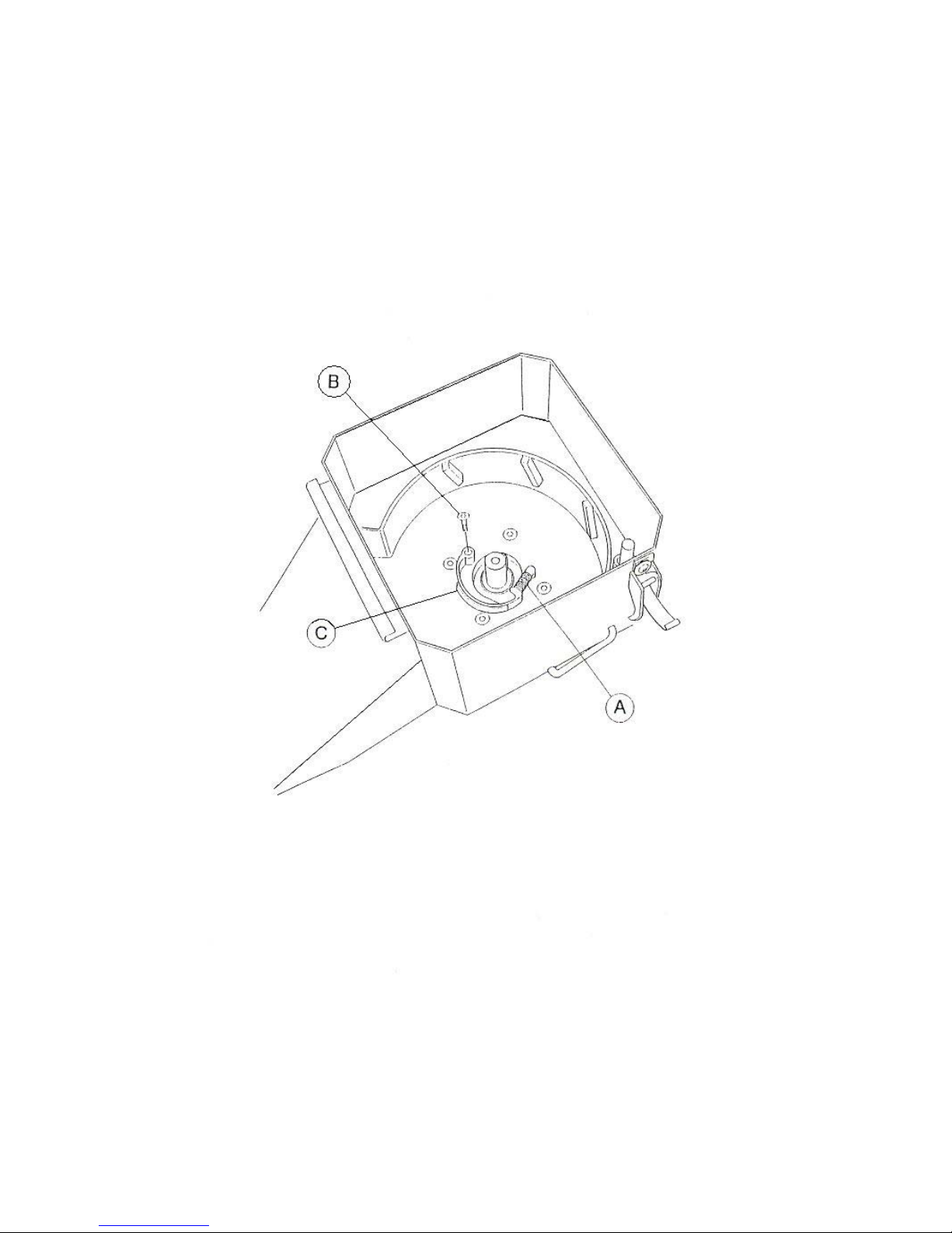
If a fault occurs on the spring, thereby interfering with the immediate stop of the blade disk
when the feeder pipe is opened, it is necessary to replace the spring itself (Fig. 6 Point A)
To replace the spring, we recommend that you follow the instructions below:
- stop the engine and disconnect the spark plug wire.
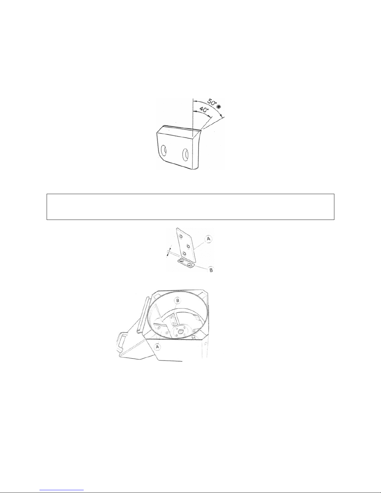
-set the knob (Fig. 2, point A) to position 2
-place the safety lever on “machine stop” (fig.2, point C, pos.4)
- release the feeder pipe from the shredder body using the two hooks provided (Fig. 2
point B), and disassemble;
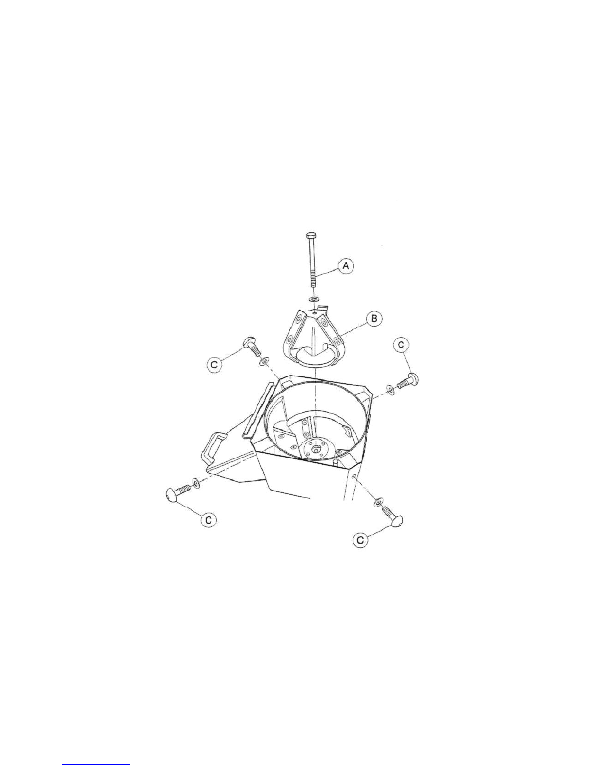
- unscrew and remove the four screws (visible from outside the shredder body) holding
the support pipe of the counter-blade (Fig.3, point C) ;
- remove the counter-blade support pipe (Fig.1, point E);
- unscrew the central screw holding the rotor (Fig. 3 point A)
- remove the blade disk (Fig. 1 point C). If it is stuck in position, you must use an
extractor, using leverage against the two holes on either side of the central disk hole;
- unscrew the screw holding the brake block (Fig. 6 point B)
- Remove the brake block (Fig.6, point C) and replace the existing spring with a new one
in perfect condition, supplied by the shredder manufacturer.
Then re-assemble the various parts by following the same procedure in reverse order.
WARNING
When re-positioning the counter-blade support pipe, make especially sure that there is a
space of no less than 2 mm between the counter-blade and the blade (Figure 5).
After completing assembly, make sure that the feeder pipe rests firmly against the
shredder body and is properly connected via the knob shown in Fig. 2 point A (position 1
to lock) and the side hooks (Fig. 2 point B), make sure that the safety lever has
automatically sprung into its “work” position (fig. 2, point C, pos.3); then check the rotation
to see whether the machine is working smoothly and check the efficiency of the safety
device, thus that the blade disk stops immediately when the feeder pipe is opened,
following the instructions provided in Chap. 9 of the Instruction and Maintenance manual
(section «Check the efficiency of the safety device»).