Band-it 2590 User manual

2590
Model No: __________________________
Serial No: __________________________
DEALER:
Name: _____________________________
Address: ___________________________
City/State: __________________________
Phone No: __________________________
Delivery Date: _______________________
Engine Make: _______________________
Serial No: __________________________
Clutch Make: ________________________
Model: ___________ S/N _____________
Copyright 6/18
ATTENTION:
Depending on what replacement parts you are ordering, we will need the following information:
CHIPPER COMPONENTS
Serial Number
Model Number of Chipper
ENGINE COMPONENTS
Brand
Engine Serial Number
Engine Model Number
CLUTCH COMPONENTS
Brand
Clutch Serial Number
Clutch Model Number
MODEL 2590
OPERATING & PARTS MANUAL
6750 Millbrook Rd. • Remus, MI 49340 • 1-989-561-2270
MANUFACTURED BY BANDIT INDUSTRIES, INC
PHONE: (989)561-2270
PHONE: (800)952-0178 IN USA
FAX: (989)561-2273 ~ SALES DEPT.
FAX: (989)561-2962 ~ PARTS/SERVICE
WEBSITE: www.banditchippers.com

WARNING
!
ADVERTENCIA
!
Breathing diesel engine
exhaust exposes you to
chemicals known to the
State of California to cause
cancer and birth defects or
other reproductive harm.
• Always start and
operate the engine in a
well-ventilated area.
• If in an enclosed area,
vent the exhaust to the
outside.
• Do not modify or tamper
with the exhaust system.
• Do not idle the engine
except as necessary.
For more information go to:
www.P65warnings.ca.gov/diesel
Respirar gases de escape de
motores diesel le expone a
quÍmicos conocidos por el estado
de California como causales de
cáncer y defectos congénitos u
otros daños reproductivos.
Para mayor informaciÓn visite:
www.P65warnings.ca.gov/diesel
• Siempre encienda y opere el
motor en áreas bien ventiladas.
• Si está en un área cerrada,
ventile escape hacia el exterior.
• No modifi que ni altere el
sistema de escape.
• No deje el motor en ralentÍa no
ser que sea necesario.
SPW-46 8/18
SPW-47 8/18
Cancer and
Reproductive
Harm
WARNING
!
ADVERTENCIA
!
Cáncer y daño
reproductivo
www.P65warnings.ca.gov
CALIFORNIA PROPOSITION 65

Copyright 2/17 FORM #WV-117
I have inspected this equipment and nd it in correct working condition. To the best of my knowledge,
the customer and his/her personnel are aware of, and agree to the above procedures.
Signed: ________________________________________________________ Date: ______________
(Dealer Representative)
The equipment has been thoroughly checked by the above named dealer representative, and I am
satised with his/her instructions. I have also read, understand, and agree to reverse side of page.
Signed: ________________________________________________________ Date: ______________
(Customer)
WARRANTY VALIDATION FORM
(WHOLE TREE & LOADER FED CHIPPER)
PURCHASER / OWNER INFORMATION:
Company Name __________________________________ Contact Name _____________________
Mailing/Street Address _______________________________________ City _______________________
State ___________________ Zip Code _______ Country ______________ TelephoneNumber(__ ) ________
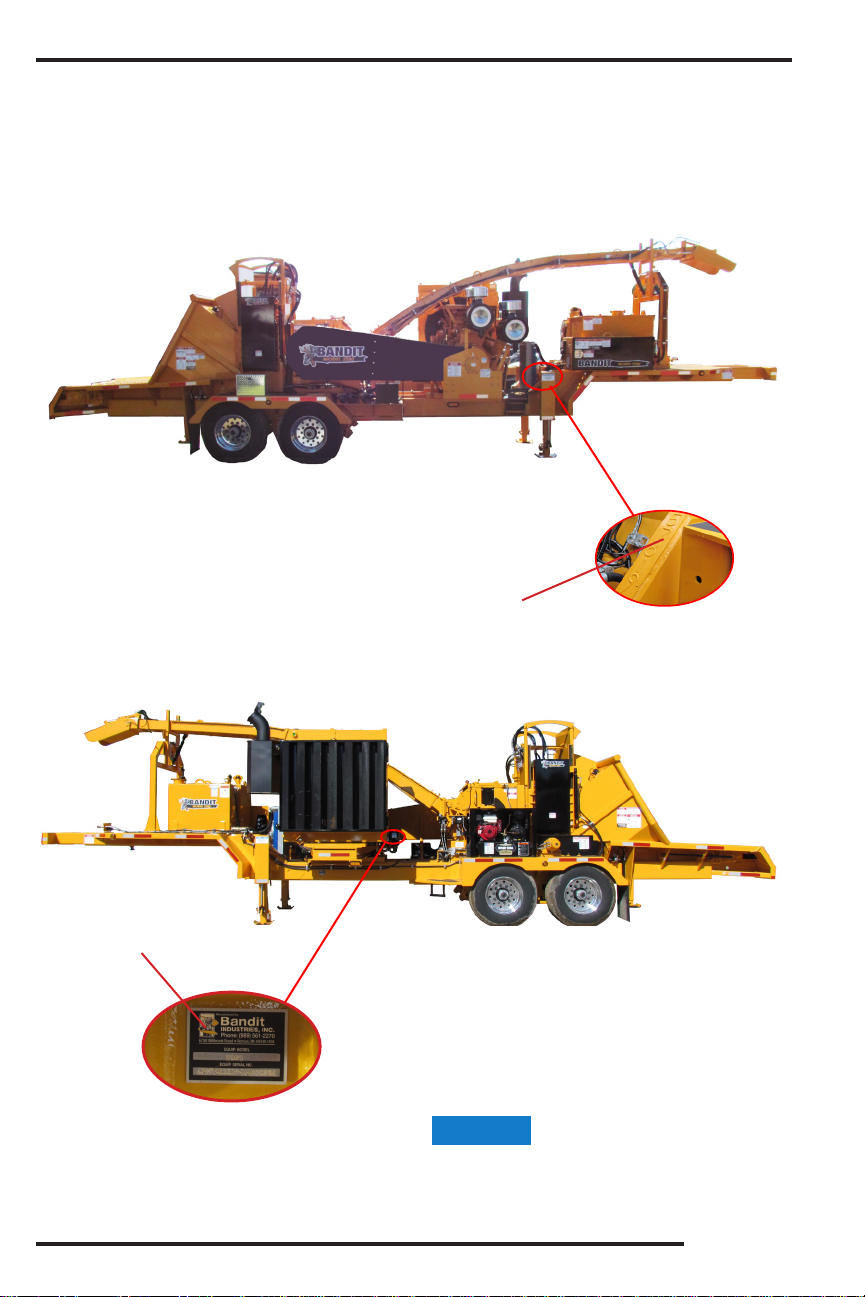
E-mail ____________________________ Machine Model No. _______ Date Put Into Service ______
Machine Serial No. ____________________ Machine Work Order No. ________ Machine Hours _______
Engine Make _________________ Engine Serial No. __________________ Machine Color _______
DEALER / SELLER INFORMATION:
Dealer/Seller Name _______________________________ Contact Name _____________________
Mailing/Street Address _______________________________________ City _______________________
State ___________________ Zip Code _______ Country ______________ TelephoneNumber (__ ) ________
IMPORTANT - WARRANTY WILL BE DEEMED NULL AND
VOID IF THIS FORM IS NOT FILLED OUT COMPLETELY AND
ACCURATELY AND RETURNED TO THE CUSTOMER DATA
DEPARTMENT WITHIN 10 DAYS OF EQUIPMENT DELIVERY
1. _____ The customer has received instruction and fully understands all operational, safety and maintenance requirements
of the equipment.
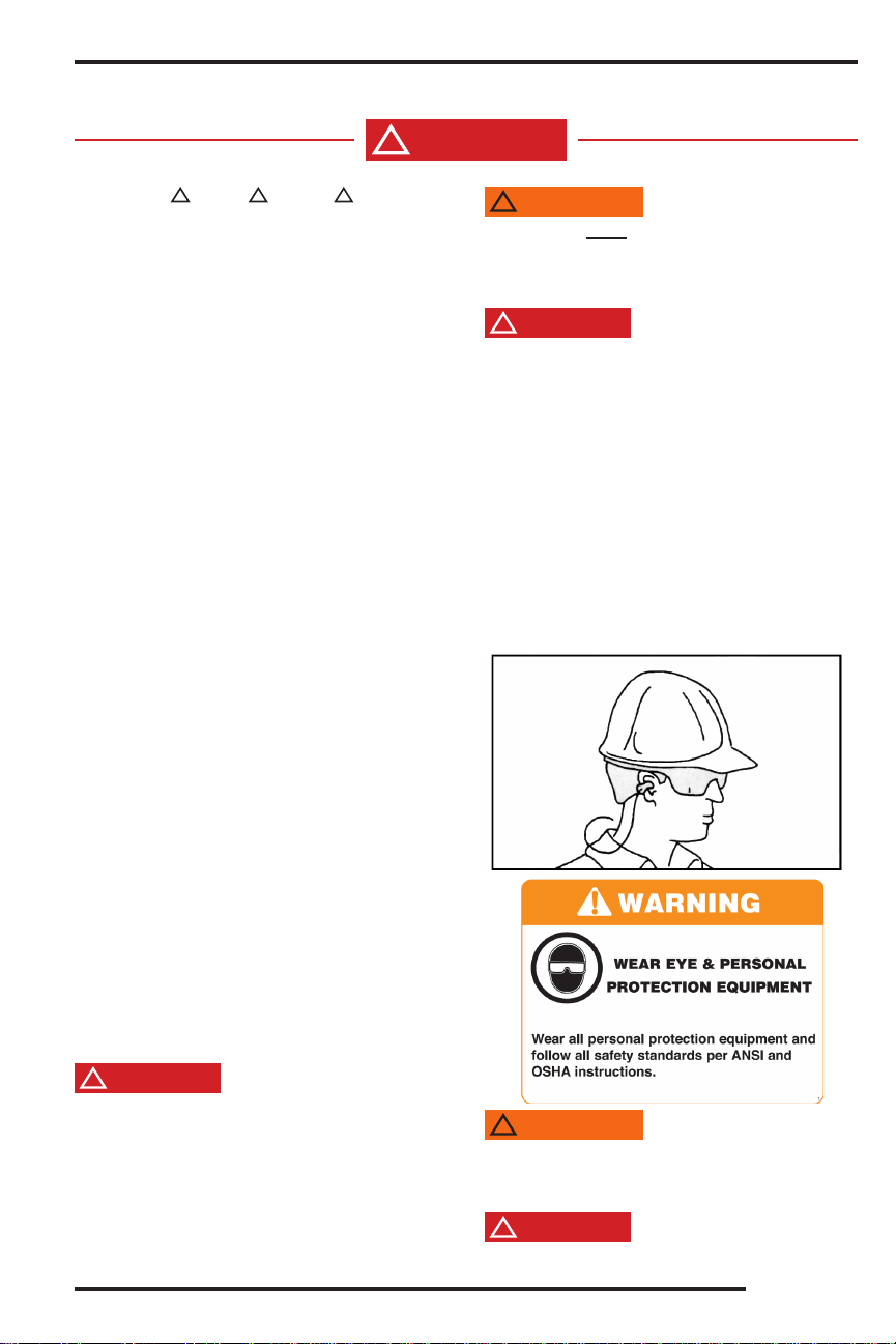
2. _____ The customer has received instruction and fully understands that everyone within 100 feet of the machine must
wear proper personal safety equipment including hard hat, face shield, safety glass, gloves, ear protection and/or other
items per OSHA and ANSI requirements.
3. _____ The customer has received instruction and fully understands the equipment maintenance schedules and procedures.
The customer understands that it is their responsibility to perform scheduled maintenance that includes periodic relief valve
adjustments, retightening all fasteners as needed, periodic cleaning of ow divider, clutch and belt adjustments, and other
items.
4. _____ The customer has received instruction and fully understands not to reach into the infeed hopper with hands or feet.
5. _____ The customer has received instruction and fully understands that the operators must always be located within
easy reach of all feed control and shut down devices.
6. _____ The customer has received instruction and fully understands that this machine is designed to be ‘loader’ fed
and is to follow all feeding instructions in the manual. The customer understands that under no circumstances should the
operator hand feed these machines or use anything other than mechanical devices, knuckle boom loader or the machines
loader to feed these machines.
7. _____ The customer has received instruction and fully understands the purpose of and proper operation of any and all
safety devices and guards. The customer understands to never attempt to override any safety device or guard.
8. _____ The customer has received instruction and fully understands that before performing any maintenance on the machine
the ignition key must be removed, the cables must be completely disconnected from the battery, the disc/drum must have come to
a complete stop, and the disc/drum lock must be installed. The customer understands they must allow the necessary time for the
disc/drum to come to a complete stop before opening the disc/drum housing or start any maintenance or service procedures. The
customer has received instruction and fully understands the purpose of the beltshield inspection hole and that they are never to attempt
any maintenance or service procedures until visually conrming the belts have come to a complete stop.
9. _____ The customer has received instruction and fully understands that the machine is not to be operated without the
factory approved hood pin assembly in place and padlocked, the machine is not to be operated with any type of make
shift hood pin, and the machine is not to be operated under any circumstances with the chipper hood open or unsecured.
10. _____ Customer has reviewed and fully understands limited warranty, and all written and visual instructions.
11. _____ The customer has received instruction and fully understands that warranty will not apply if the machine is operated
with replacement parts or equipment not manufactured or recommended by Bandit Industries, Inc.
12. _____ Customer has received, been advised, and understands the manuals, and the Safety/Service video supplied
with the chipper. A video is supplied for equipment models as available.
13. _____ All Danger, Warning and Operational decals are properly displayed on equipment and fully understood by customer.
14. _____Customer has been instructed, understands, and agrees that all potential operators must: See the supplied video,
be instructed on all the Danger, Warning and Operational decals, read the manual and follow the procedures.
Customer Data Department
6750 Millbrook Road
Remus, MI, USA 49340
Phone: (800) 952-0178 in USA
Phone: (989) 561-2270
Fax: (989) 561-2273
Website: www.banditchippers.com

All of the employees that build your equipment strive to manufacturer the very best quality product on
the market. We would appreciate your eorts in letting us know how we are doing.
We would like you to operate your machine for thirty (30) days and then ll out this questionnaire and mail it to us.
This will help us to keep producing a good product and improving our products through your recommendations.
DATE PURCHASE: ______________________
MODEL: ________________________________
SERIAL NUMBER: _______________________
DEALER NAME: ________________________
_______________________________________
Copyright 2-17 FORM #Q-111
TO BE RETURNED AFTER THIRTY (30)
DAYS OF OPERATION
Please return to: Customer Data Department
6750 Millbrook Road
Remus, MI 49340
Phone: (800) 952-0178 in USA
Phone: (989) 561-2270
Fax: (989) 561-2273
Website: www.banditchippers.com
EQUIPMENT QUALITY REPORT
1. Did your machine perform to your expectations? _______________________________________
2. Was the machine delivered on schedule? _____________________________________________
3. Was the paint color and nish to your satisfaction? ______________________________________
4. Was machine equipment as ordered? ________________________________________________
5. Did all welds appear to be high quality? ______________________________________________
6. Was the overall machine to your liking? ______________________________________________
7. What problems have you experienced? ______________________________________________
8. Have any components regularly loosened that caused problems? __________________________
9. Does the hydraulic system seem to have adequate power for feeding wood into the machine? _____
10. Is the machine manufactured to accommodate service in an adequate manner? If not, please explain:
_______________________________________________________________________________
11. General comments and/or suggestions: ________________________________________________
_______________________________________________________________________________
_______________________________________________________________________________
12. Would you like to be contacted concerning more of our equipment? ________________________
YOUR COMPANY: ________________________________
NAME: __________________________________________
ADDRESS: ______________________________________
CITY: ___________________________________________
STATE & ZIP: _____________________________________
PHONE: ( ____ ) _________________________________
E-MAIL: _________________________________________

Bandit
1Copyright 6/18
MODEL 2590 TABLE OF CONTENTS
TABLE OF CONTENTS
ANY PART, PORTION, DESIGN, NUMBER, SPECIFICATION, AND/OR DIMENSION IN THIS
MANUAL IS SUBJECT TO CHANGE WITHOUT NOTICE BY THE MANUFACTURER.
NOTICE
PAGE
INTRODUCTION & WARRANTY ........................................................... 2
SERIAL NUMBER LOCATIONS ............................................................ 6
EQUIPMENT SPECIFICATIONS ........................................................... 13
DECALS ................................................................................................... 14
CONTROLS ............................................................................................. 21
TRANSPORTATION PROCEDURES .................................................... 34
MAINTENANCE ...................................................................................... 37
HYDRAULICS ......................................................................................... 73
ELECTRICAL .......................................................................................... 84
REPLACEMENT PARTS ........................................................................ 85
INFEED HOPPER COMPONENTS ................................................ 86
BEARING COMPONENTS ............................................................. 95
CHIPPER COMPONENTS .............................................................. 88
CHIPPER KNIFE & HARDWARE ................................................... 92
ANVIL HARDWARE ........................................................................ 94
DISCHARGE COMPONENTS ........................................................ 96
LOADER COMPONENTS ............................................................... 98
FRAME & ACCESSORY COMPONENTS ..................................... 100
FRONT STABILIZER COMPONENTS ........................................... 102
FUEL TANK COMPONENTS .......................................................... 103
HYDRAULIC TANK COMPONENTS ............................................. 105
ENGINE COMPONENTS ................................................................ 106
HYDRAULIC COMPONENTS ......................................................... 108
AIR BRAKE COMPONENTS .......................................................... 115
SERVICE RECORD ................................................................................ 116

Bandit
2
Copyright 6/18
INTRODUCTION & WARRANTY
INTRODUCTION
The purpose of this manual is to provide the user with speci cations and procedures for the
operation, maintenance and repair of this BANDIT product. As with any piece of equipment, safety
should always be a constant thought while the machine is being operated, serviced or stored.
In order to highlight this consideration, the material which addresses safety is proceeded by the
following signal words:
The equipment is designed and manufactured in accordance with the latest product industry
standards. This alone does not prevent injury. It is the operator’s responsibility to use good
judgement and follow the warnings and instructions as indicated in this manual, on the machine
and follow all safety standards per ANSI and OSHA instructions.
Improper use of the product can result in severe personal injury. Personnel using the equipment
must be quali ed, trained and familiar with the operating procedures as de ned in this manual,
prior to operating the product.
It is the responsibility of the owner or employer to ensure that the operator is trained and practices
safe operation while using and servicing the machine. It is also the owner’s responsibility to provide
and follow a regularly scheduled preventative maintenance and repair program on the product,
using only factory approved replacement parts. Any unapproved repairs or modi cations may
not only damage the machine and its performance, but could result in severe personal injury.
Unapproved repairs or modi cations will void warranty and eliminate manufacturer of any liability
claims. Consult the equipment manufacturer with any questions.
Each machine is shipped with a manual, a customer’s check sheet on the product, and any
available parts & service manuals on component parts not produced by this manufacturer.
Additional copies of these manuals and check sheets can be purchased from the manufacturer,
or through the dealer. Engine parts, service and maintenance manuals MUST be purchased
through the engine manufacturer or their dealer.
The producer of this Bandit product reserves the right to make any modi cations or revisions to
the design or speci cations of its machine without advance notice. The producer also reserves
the right to change machine and part prices as needed without advance notice.
NOTICE
WARNING
!
WARNING
!
Signal Word Likelihood of Occurrence Degree of Potential
Injury or Damage
Will occur if warning is ignored
Can occur if warning is ignored
Will or can occur if warning is ignored
Important, but not hazard related
Severe
Minor
Minor to Severe
Severe
CAUTION
!
NOTICE
DANGER
!
WARNING
!


Bandit
6
Copyright 6/18
MODEL 2590
TYPICAL CHIPPER SERIAL NUMBER AND/OR
WORK ORDER NUMBER LOCATIONS
1. Engine Frame (Right Side)
2. W/O # on top of frame side (Right Side)
The engine information is located on the engine
block. The clutch information is located on the
clutch plate (if equipped).
2
1
SERIAL NUMBER LOCATIONS
NOTICE

Bandit
7Copyright 6/18
MODEL 2590 SAFETY PROCEDURES
DANGER
!
Before starting the machine, take a minute to
check a few things. The machine should be in an
area restricted from people passing by. This area
around the machine must be free of all objects that
can obstruct your movement when working with the
machine. The machine should be checked for loose
tools or foreign objects, especially in the infeed
hopper area. All tools not in use should be secured
in a tool box.
WARNING
!
Operators must
at all times be located within
easy reach of all feed control and shut-o devices
when the unit is running. They must be attentive and
prepared to activate the devices.
DANGER
!
Torn or loose clothing is more likely to get caught
in moving machinery parts or tree branches. Keep
such items as long hair, shirt sleeves, and shirt tails
properly contained. Avoid wearing necklaces, rings,
watches, and especially neckties while operating this
machinery. Make sure the machine is in excellent
condition, and all the guards are in place, tight and
secure.
Wear all personal protection equipment and follow
all safety standards per ANSI and OSHA instructions.
Examples of equipment: hard hat, face shield, safety
glasses, gloves, ear protection, etc. Do not wear
gauntlet or secured t gloves. Always keep a fully
charged re extinguisher with the machine while
operating or servicing the machine.
SAFETY PROCEDURES
DANGER
!
The words
!Danger, !Warning, !Caution, and
Notice are used on the safety decals and throughout
this manual, to make you aware of the safety
procedures. These procedures are very important,
read and obey them.
YOUR SAFETY IS VERY IMPORTANT TO US!
This machine is equipped with safety decals,
guards and designs for your protection.
Don’t ever take the machine for granted, always be
cautious and careful when operating your equipment.
Read and follow all the instructions in your
manual thoroughly. Your safety is dependent on
your knowledge of how to operate and maintain this
machine. You may obtain additional copies of this
manual from your Bandit Dealer.
Before operating machine, you must have all
potential operators; read and understand manuals
and decals, watch the video and follow the
recommendations.
Regardless of how hard a manufacturer tries to
produce a safe machine, accidents still happen.
Normally accidents are caused by people making
mistakes. They do not read the manual, they ignore
warning decals or do not use lockouts provided for
their safety. This normally happens after the person
has become accustomed to the machinery. In the
initial start up and operation of the machinery, they
are cautious, they are very careful because they do
not understand the machine.
This equipment is intended for use by adults
who have been properly trained and are physically
capable of operating the machine safely. Never
allow minors to operate this machine. Never operate
any machine while under the in uence of drugs or
alcohol. Never operate equipment that is in need of
repair or adjustment. Keep children, bystanders and
animals clear of working area.
There must be at least two qualified and
trained operators at the work site. They must be
positioned in safe working locations, following safety
procedures and instructions, and aware of each
others whereabouts. There must, also, be at least
two people on site during maintenance and service
procedures in case an accident should occur.
Before performing maintenance on the machine
remove all debris, oil, grease, water, snow, ice, etc.
from all machine surfaces.
WARNING
!
DANGER
!
Keep hands clear of all pinch points.

Bandit
8
Copyright 6/18
MODEL 2590
SAFETY PROCEDURES
SAFETY PROCEDURES
WARNING
!
It is very important after you have operated a new
machine for approximately an hour to shut down the
machine and recheck all nuts and bolts. It is normal
for nuts and bolts to loosen once on a new piece of
machinery. If you tighten them now, there is a good
possibility they won’t loosen again. Certain nuts and
bolts should be checked periodically such as anvil
and knife nuts and bolts, etc. for torque and t.
Most of the nuts used on the machine are self
locking. After a nut or bolt has been removed
ve times, it should be replaced to ensure proper
tightness. This is especially critical on the chipper
knife nuts and bolts!
After the engine is started, let the chipper
disc/drum turn at the lowest RPM’s possible. Listen
for any type of noise that is foreign. Any steel on steel
noise is foreign. If you hear a noise, stop the engine,
nd the problem and x it.
DANGER
!
Pay attention to the direction of the discharge
chute before chipping. Never stand in front of the
chipper discharge chute. Never direct the chute
towards anyone or anything that could cause an
accident or problems. Always stop chipping and
warn anyone that comes near the discharge area.
Failure to do this could result in severe injury. Wood
chips ying out of the discharge chute can be very
dangerous!
DANGER
!
NEVER sit, stand, lay, climb or ride anywhere
on this machine while it is running, operating, or in
transit. You will be injured.
WARNING
!
It is very important after you have operated a new
machine for approximately an hour to shut down the
machine and recheck all hydraulic ttings. Relieve
all pressure and retighten as needed.
DO NOT GO NEAR HYDRAULIC LEAKS! High
pressure oil easily punctures skin causing serious
injury, gangrene, or death. Avoid burns from uid.
Hot uid under pressure can cause severe burns.
DO NOT use ngers or skin to check for leaks. Lower
load or relieve hydraulic pressure before loosening
ttings. Relieve all pressure in the system before
disconnecting the lines, hoses, or performing other
work. Use a piece of cardboard to nd leaks. Never
use your bare hands. Allow system to cool down to
ambient temperature before opening any coolant or
hydraulic oil system.
In cold weather situations let your hydraulic
system idle for approximately 15 minutes to allow
the system to warm up to operating temperature.
DANGER
!
DO NOT operate this machine indoors! Exhaust
fumes can be fatal. Never refuel while the machine is
running. Never refuel in the shop or building. Always
refuel in a well ventilated area, away from sparks
or open ames, DO NOT SMOKE. Extinguish all
smoking materials. Wipe up all spilled fuel before
restarting the engine. Do not ll above 1/2” (12.7mm)
from top of tank.
To obtain the most from your machine, for the
least amount of cost, it is a good practice to set up
and follow a scheduled preventative maintenance
program. It will eliminate many possible problems
and down time.
DANGER
!
Never reach into the infeed hopper area of
the machine, there is never any reason to. The
feedwheels are designed to pull trees and brush of
any length into the machine. Pulling a hand, arm,
foot or entire body through the machine is much
easier than pulling a tree. Do not think you will be
able to pull yourself free of the feedwheels, they
will not let go. There is absolutely no reason to
work inside of the infeed hopper. If the feedwheels
become tangled or clogged: disengage clutch, wait
for the disc/drum to come to a complete stop, turn
off engine, remove the ignition key, make sure
the ignition key is in your possession, install the
disc/drum lock pin, and disconnect the battery before
cleaning them out. If there are short pieces, just leave
them until feeding longer pieces. While the longer
pieces are feeding, simply put the short pieces on
top of them. The longer pieces will take them on
into the machine.
If there is larger diameter wood, try to feed it with
smaller diameter wood. Start a small diameter limb
which will partially open the feedwheels. Once the
feedwheels are partially open it is much easier to
insert the larger diameter wood.
When feeding larger diameter wood, listen
for the engine to possibly lug down. If it starts
lugging down stop the feedwheels by stopping
the feed system, and let the engine recover to full
speed. If the machine is equipped with Autofeed
and it is functioning properly, the feed system will
automatically stop to let the engine recover. This will
help stop the machine from plugging the discharge
chute.
NOTICE
The Bandit has only been run for a short time to
test proper hydraulic pressures, possible leaks, etc.
The fuel tank will be empty. Fuel is provided through
a small auxiliary tank for testing. This immensely
helps maintain safety in our manufacturing facility
and while shipping.

Bandit
9Copyright 6/18
MODEL 2590
SAFETY PROCEDURES
SAFETY PROCEDURES
Before attempting any type of maintenance,
disengage clutch, wait for the disc/drum to come to a
complete stop, turn o engine, remove the ignition key,
make sure the ignition key is in your possession, install
the disc/drum lock pin, and disconnect the battery.
ALWAYS install the disc/drum lock pin to prevent
inadvertent rotation. On disc chippers insert lock pin
through lock pin tube on the belly band under hood
rest. On drum chippers insert lock pin through lock
pin tube on side of drum housing.
Simply slide the lock pin into the disc/drum lock
tube. This is to ensure that the chipper disc/drum
cannot be started while you are working inside the
machine. If for some reason the chipper disc/drum
would start to turn, it would simply hit the lock pin.
DO NOT remove the hood pin until the chipper
disc/drum has came to a complete stop
. The chipper
disc/drum will coast for several minutes after the
engine is shut down. Always wait at least several
minutes.
DO NOT operate this machine without the Hood
Pin in place. Do not operate the machine with any
type of makeshift hood pin or an improperly installed
hood pin! The Hood Pin MUST be padlocked.
DO NOT operate the machine with the chipper
hood open under any circumstances.
Never use jumper cables during freezing
temperatures. Tow the machine inside and allow the
battery time to warm up. If the machine must be start-
ed outside, inspect the battery acid for ice formation.
Explosion will occur with a frozen battery. If the
machine is going to be operated in excessively cold
conditions, a larger cold cranking amp battery may be
needed to ensure proper and prompt starting. Never
use jumper cables in a con ned or unventilated area.
Battery acid fumes are explosive. Battery acid can
cause severe burns. Never expose an open ame
or spark near the battery. Keep all burning materials
away from the battery. When servicing the battery,
shield eyes and face, and do not smoke. Service in
a well ventilated area.
Keep the machine in good condition. Be sure the
machine is in good operating condition and that all
safety devices, including guards and shields are
installed and functioning properly. Visually inspect
the machine daily before starting the machine. Refer
to the “Daily Start Up & Maintenance”. Make no
modi cations to your equipment unless speci cally
recommended or requested by Bandit Industries Inc.
Avoid moving parts. Keep hands, feet, and clothing
away from power driven parts. Keep all guards and
shields in place and properly secured.
Never feed any materials that might contain
wires, stones, nails, metal objects, or any foreign
object which may damage the knives and become
dangerous projectiles.
DANGER
!
DANGER
!
DANGER
!
DANGER
!
DANGER
!
WARNING
!
Chipper knives are sharp and can be dangerous.
It is always necessary for your protection to be
extra careful and wear proper hand protection when
handling knives.
The knives must be securely fastened and torqued
in position. If one comes loose or breaks during
operation, someone or something may get injured
or damaged.
DANGER
!
DANGER
!
DO NOT operate this machine unless all hydraulic
control devices operate properly. They must function,
shift and position smoothly and accurately at all
times. Faulty controls can cause personal injury!
WARNING
!
DO NOT attempt to hand feed this machine. DO
NOT operate the loader arm or chipper when anyone
is standing or working in front of the chipper infeed
opening. Failure to do this could result in serious
injury or death.
DANGER
!
DO NOT hand feed this machine! This machine is
designed to only be fed by a mechanical log loader.
Feeding material into this machine by hand is not
permitted or authorized. Severe injury or death can
result!
DANGER
!
DO NOT run or operate this machine with any
door/compartment open. Door enclosures are
guards, you can be injured if open during operation.
DANGER
!
EXPLOSION HAZARD: Ultra low sulfur diesel
(ULSD) poses a greater static ignition hazard than
earlier diesel formulations with higher sulfur content.
Avoid death or serious injury from re or explosion;
consult with your fuel or fuel system supplier to
ensure the delivery system is in compliance with
fueling standards for proper grounding and bonding
practices.
WARNING
!

Bandit
10
Copyright 6/18
MODEL 2590
Use Chain
Use
Wooden
Block
Use Yoke
Lock Pin
The machine was built with a chipper hood
engine disable plug which disables the engine if it
is not installed properly with the hood pin holding
the chipper hood in the closed position. Correctly
installed and maintained, the engine will not start or
it will shut o if the chipper hood engine disable plug
is disconnected. The chipper hood must
NEVER be
opened, or pushed closed if the chipper disc/drum
is turning.
DO NOT slam the chipper hood to the open
position. This will cause damage to the hinge. If
your hinge has become damaged by slamming
the hood to the open position,
Replace The Hinge
Immediately!
If the hinge has become damaged it
will cause misalignment of the hood, the chipper
disc/drum may then hit the hood and cause a serious
accident! Lubricate the hood hinge daily.
Do not work inside the mouth of the chipper or
around the feedwheel(s), until you have installed the
yoke lock pin completely and securely to help keep
the top feedwheel in the raised position. Remove
top wheel springs if equipped, block and chain top
wheel up before doing any work inside throat.
Never turn the chipper disc/drum by hand, always
carefully use a pry bar or wood bar. This will help
prevent the person turning the disc/drum from being
injured should the disc/drum break loose.
A sight hole in the chipper beltshield has been
provided. If chipper belts are moving do not open
chipper hood. Do not stick ngers in sight hole.
DANGER
!
SAFETY PROCEDURES
SAFETY PROCEDURES
DANGER
!
DANGER
!
DANGER
!
WARNING
!
If the chipper is properly maintained and operated
correctly, the chipper should not plug. In the unlikely
event that the chipper becomes plugged, do not
attempt to clean out the discharge or chipper housing
in the eld. Take the machine to a local dealer or
professional shop. If the machine is a rental, take it
back to the rental company.
If the discharge or hood need to be removed,
always use some sort of mechanical device like an
overhead hoist, loader, lift truck, etc. that is rated for
lifting that component. Follow all OSHA instructions
for lifting.
Before opening or closing the feedwheel trap
door: disengage clutch, turn o engine, wait for the
disc/drum to come to a complete stop, install the
disc/drum lock pin, disconnect battery, and make
sure the ignition key is in your possession. In the
event that dirty material is being run through the
chipper the feedwheel trap door can be opened.
DANGER
!
DANGER
!
DANGER
!
Do not attempt to start the engine or engage the
engine PTO (power-take-o ) system on this machine
if the chipper disc/drum is jammed or frozen in place.
If you do, you will damage or ruin the drive belts
and/or the PTO which will not be covered under
warranty and will cost you down time and money.
NOTICE
Do not work on the machine if the engine is
running with the clutch disengaged. A clutch can
self engage if either the pilot or throw-out bearing
happens to seize to the main output shaft.
There are various types of clutches (PTO’s)
available for this type of equipment. Make sure to
study the original clutch manufacturer’s manual
that is provided with the machine and follow its
instructions for operation, service, and adjustments.
Some styles require clutch engagement to be
maintained so that it takes a lot of force, others will
require very little force, and some are push button,
electric, manual lever, or hydraulic activation. Each
di erent style clutch (PTO) is a very expensive item
that will fail if not correctly
maintained and adjusted.
It will be quite costly if a few minutes are not taken
daily, weekly, and monthly to keep the clutch serviced
as required.
The operator must take care in the engagement
and disengagement of the clutch, engine RPM
should always be at idle speed. When the engine
has su ciently warmed up, bump the clutch handle
against engagement to start the chipper disc/drum
turning. This will have to be repeated until the chipper
disc/drum is turning at proper ratio with engine RPM.
Then push the handle all the way in gear until it locks
into position securely. After engagement raise engine
RPM to full throttle. Engaging and disengaging the
clutch at high engine RPM will quickly and excessive-
ly wear out clutch plates as well as bearings. Refer
to clutch manufacturer’s manual for proper service
and operation.

Bandit
11Copyright 6/18
MODEL 2590
Before you begin to transport your trailerized
machine follow all of the transportation procedures
on pages 34 - 36. Make sure that the tongue
has been raised to the proper height and attach
the machine securely to the towing vehicle. Once
secured to vehicle, locate tongue jack and secure it
in the transport position. Always hook safety chains
to vehicle by crossing them under the tongue allowing
enough slack to avoid binding or dragging the ground
when making turns. Check brakes and highway lights
make sure that they are all operating properly. Check
that the plug terminal functions match the towing
vehicle for proper operation. Make sure that the
discharge chute is in the transport position pointed
over the tongue of machine and the transport bolt is
securely in its place. Be sure to check tire pressure
before you begin to transport the machine. Close the
folding pan, if equipped for the infeed hopper and
make sure spring latches are locked into place. If
machine is equipped with a vise, make sure to secure
in place and clamp jaws closed. Close and secure
any of the following, if equipped: tool box, battery box,
engine cowl doors and side panels, radiator debris
screens, inspection doors, cabinet doors, housing
covers, tank caps and covers, etc.
WARNING
!
SAFETY PROCEDURES
SAFETY PROCEDURES
Tongue jacks or optional rear stabilizers, whether
hydraulic or manually operated are designed to
stabilize the machine. The tongue jack or rear
stabilizers are not designed to hold the machine
o the ground at any time. Install secure blocking
and / or chocking as needed. Before transporting
the machine, ensure the tongue jack and rear
stabilizers are fully retracted and secured to the
transport position.
Check laws and regulations. Know and obey all
federal, state, and local laws and regulations that
apply to your work situation and the transportation
of a machine this size.
NOTICE
WARNING
!
Always block the tires and the machine tongue
whenever the machine is unhooked for operation.
DO NOT rely on the hydraulic stabilizers. With the
bouncing and rocking, the stabilizer cylinders may
have a tendency to leak o allowing the machine
to drop down slowly. Do not depend on them for
stability. Install secure blocking as needed.
DANGER
!
CLEAN MACHINE OF ALL DEBRIS! DO NOT
leave this machine unattended until all potential re
debris is removed, no re or smoldering exists, and
hot spots are cold. The engine creates many hot
spots including: exhaust manifold, exhaust, turbo
(if equipped), etc. Remove all flammable debris
such as wood, chips, leaves, oils, fuels, etc. from
engine exhaust, engine turbo (if equipped), beside,
around, and under engine, around and under tanks,
inside belt shields and guards, inside battery and tool
boxes, inside cabinets (if equipped), and anywhere
materials collect. ALWAYS keep several type A:B:C re
extinguishers operational and on the job at all times.
WARNING
!
Expensive damage to the Bandit will occur if
proper preparation is not taken before welding on
the machine. Be sure to disconnect both battery
cables and the engine ECM (engine control module)
before welding. Follow the speci c Engine MFG.
instructions for proper welding and grounding
procedures, before attempting to weld on the
machine. If welding on the machine, do not ground
the welder through the machine bearings, ground
near work to be performed.
NOTICE
Operation of this equipment may create sparks
that can start res around dry vegetation. A spark
arrester may be required. The operator should con-
tact local re agencies for laws or regulations relating
to re prevention requirements.
WARNING
!
Refer to the Material Safety Data Sheet (MSDS)
for information pertaining to the knife babbitt material
including the health hazard information, rst aid
procedures, special handling procedures, disposal
procedures, etc. If needed, contact your nearest
dealer or Bandit Industries for the knife babbitt
MSDS.
WARNING
!
DANGER
!
DO NOT operate this chipper or loader arm when
anyone is performing any type of maintenance
to the machine. Before attempting any type
of maintenance disengage clutch, wait for the
disc/drum to come to a complete stop, turn off
engine, remove the ignition key, make sure the
ignition key is in your possession, install the
disc/drum lock pin, disconnect the battery, and the
loader, if equipped, is positioned on the ground.
Failure to do this could result in serious injury or death.
DANGER
!
Do not touch hot machine surfaces. The machine
surfaces may be hot due to the machine operating
recently or the machine setting in the sunlight.
Before performing maintenance on the machine re-
move all debris, oil, grease, water, snow, ice, etc.
from all machine surfaces.
WARNING
!

Bandit
12
Copyright 6/18
MODEL 2590
Do not attempt to operate the machine on an ascending or descending slope of more than 25° or 46% or
a side slope of more than 17° or 30%, it is Dangerous and could be Fatal. This is the maximum slope grade
the machine can be operated on if the hydraulic system, self propelled undercarriage, and engine are running
at maximum performance and good traction is sustained.
IF MACHINE IS EQUIPPED WITH A SELF PROPELLED UNDERCARRIAGE
Machines equipped with undercarriage tracks are shipped with a manual from the track manufacturer.
Refer to it for service, operation, and safety information.
SAFETY PROCEDURES
SAFETY PROCEDURES
WARNING
!
25° MAX.
17° MAX.
Maximum Slope Grade
Diagram shows percentage to degree of slope.
Percentage is in vertical feet for every 100 horizontal feet.
Ascending or Descending Slope Side Slope
100 FT. (30.5 m) 100 FT. (30.5 m)
46 FT.
(14 m)
(46%) 30 FT.
(9.1 m)
(30%)
25° MAX.
17° MAX.
The machine should never be parked on a slope
at any time. The machine can coast or creep causing
equipment damage and/or personal injury.
Make sure everyone is clear of machine before
moving the machine. Stay clear of
undercarriage
travel system
when the machine is moving.
DO NOT entangle feet or hands in undercarriage
travel system.
NEVER
sit, stand, lay, climb or ride anywhere
on this machine while it is running, operating, or in
transit. You will be injured.
Use EXTREME CAUTION
when traveling over
non-level surface! This machine can tip over or tip
backwards on non-level surface. You will cause
engine damage, machine damage and possible
personal injury!
Any increase from the specified maximum
operating angles may cause loss of lubrication
function and damage the engine.
DANGER
!
DANGER
!
DANGER
!
DANGER
!
DANGER
!
WARNING
!
CALIFORNIA
Proposition 65 Warning
Diesel engine exhaust and some of its
constituents are known to the State of
California to cause cancer, birth defects,
and other reproductive harm.

Bandit
13Copyright 6/18
MODEL 2590
Approximate Dimensions & Weights
(Dimensions & weights will vary depending on optional equipment)
EQUIPMENT SPECIFICATIONS
Model 2590 Trailer
Height: 144” (3.7 m)
Length: 423” (10.7 m)
Width: 113” (2.9 m)
Weight: 29,000 - 35,000 lbs. (13,154 - 15,876 kg)
Fuel Tank Capacity: 200 gal. (757 Liters)
Hydraulic Tank Capacity: 85 gal. (322 Liters)

Bandit
14
Copyright 6/18
MODEL 2590
Some decals are for optional equipment. Decal locations may vary, these are general locations.
If any decals become damaged, replace immediately.
NOTICE
Decal locations may vary, these are general locations.
DECALS
DECAL LOCATIONS - 2590
1,2,34,38
52 3,17,22,31,40,54,58 7,24,39,48
24
9
4,7,11,12
1,2,9,11,12
14,18,24,34
14,22,49,51,55,60
52
2,25,26,33,36,38,45,47,50
17
18,60,63,64,65,68,69
1
5,8,10,12,18,23 16,19,22,24,44,47
10,24,27,28,48,55
49,50,52,57

Bandit
15Copyright 6/18
MODEL 2590
LOCATION NUMBER DESCRIPTION
1. SPD-02 Moving Parts...
2. SPD-03 Danger Lockout...
3. SPD-04 Flying Discharge Material...
4. SPD-15 Loader Arm
5. SPD-16 Do Not Hand Feed...
6. SPD-17 Do Not Run Or Operate...With Door/Compartment Open...
7. SPD-19 Entanglement
8. SPD-20 Flying Objects Stand Clear...
9. SPD-22 Emergency Shut Down Only
10. SPD-25 Stand Clear - Moving Conveyor
11. SPD-28 Do Not Insert Fingers
12. SPD-29 Do Not Climb or Reach Into Infeed Conveyor...
13. SPD-30 Do Not Sit, Stand, Lay, Climb...
14. SPD-32 Do Not Operate This Machine...
15. SPD-33 Do Not Work Under...
16. SPD-37 Lockout All Energy Sources...
17. SPD-62 Stay Clear of Tongue Jack/Stabilizer
18. ID-67 Made in USA
19. INST-01 Remove To Check Torque...
20. INST-02 Yoke Lock Hole
21. INST-03 Yoke Lock Bar
22. INST-04 Arrow
23. INST-10 Stabilizer Down / Up.
24. INST-12 Grease Daily (Arrow)
25. INST-44 Proposition 65
26. INST-45 For Parts and Service...
27. INST-48 Disc/Drum Lock Tube
28. INST-49 Disc/Drum Lock Pin
29. INST-53 Hydraulic Oil...Hydrex XV...
30. INST-75 Hydraulic Oil For “PT Tech” Clutch...
31. INST-90 Tongue Down / Up
32. INST-91 Lubricant For “Twin Disc” Hydraulic Clutch...
33. INST-92 Air Brake Release
34. INST-95 Electric Plug-In Schematic
35. INST-100 Lubricate Cutter Head Bearings...
36. INST-101 Canada Engine Decal
37. INST-102 Joystick Yoke Feedwheel
38. INST-147 Remote Start Procedure
39. INST-185 Yoke Lock Instructions
40. INST-222 Electrical Plug Diagram
41. INST-274 Remote Key Pad
DECALS
DECAL LOCATIONS - 2590
Modications and/or additions of decals to this list will happen.
Consult chipper dealer or manufacturer for most current decal package.
Some decals are for optional equipment. Decal locations may vary, these are general locations.
If any decals become damaged, replace immediately.
NOTICE

Bandit
16
Copyright 6/18
MODEL 2590
Some decals are for optional equipment. Decal locations may vary, these are general locations.
If any decals become damaged, replace immediately.
NOTICE
Decal locations may vary, these are general locations.
DECALS
DECAL LOCATIONS - 2590
1,2,34,38
52 3,17,22,31,40,54,58 7,24,39,48
24
9
4,7,11,12
1,2,9,11,12
14,18,24,34
14,22,49,51,55,60
52
2,25,26,33,36,38,45,47,50
17
18,60,63,64,65,68,69
1
5,8,10,12,18,23 16,19,22,24,44,47
10,24,27,28,48,55
49,50,52,57

Bandit
17Copyright 6/18
MODEL 2590
LOCATION NUMBER DESCRIPTION
42. N-02 Maintain Lubrication...
43. N-03 Service Required Under Beltshield...
44. N-05 Frequently Adjust...PTO...
45. SPN-06 Decal Maintenance...
46. N-07 Clutch Operation...
47. N-09 Adjustable Feed Speed...
48. SPN-11 Correct Knife And Hardware...
49. SPN-14 Do Not Start To Weld...Unless...
50. SPN-16 24 Volt Circuit
51. SPN-17 Battery Disconnect Switch O (Arrow) On
52. SPN-20 Maximum Towing Speed 55 MPH (88 KPH)
53. N-30 Wait 2 minutes to disconnect battery
54. SPN-36 12 Volt Circuit
55. N-30 Must Wait 2...Before Turning O Battery...
56. N-51 Battery Instructions
57. N-69 Patents....
58. SPW-01 Do Not Go Near Oil Leaks...
59. SPW-02 Diesel Fuel Only...
60. SPW-04 Frozen Battery Can Explode...
61. SPW-06 Warning Side Slope
62. SPW-07 Warning Sound Horn
63. SPW-08 Wear Personal Protection...
64. SPW-11 Warning Parking on Slope
65. SPW-13 Warning Clean Debris
66. SPW-15 Warning Belt Shield Door
67. SPW-27 ...Equipment May Create Sparks...
68. SPW-31 Explosion Hazard...Ultra Low Sulfur Diesel...
69. 900-8901-14 Basic Safety Decal Kit (Options may require additional decals)
70. 900-8900-56 Bandit Model 2590 Logo Decal Kit
Additional Decals for Machine Equipped With A Track Undercarriage - Consult dealer or manufacturer
for general locations.
71. SPD-19 ...Minimum 10 Feet Away From Tracks...
72. SPD-38 Do Not Entangle Feet...
73. SPW-06 Do Not Attempt...Slope Of More Than...
74. SPW-07 Do Not Move Machine...Horn Is Blown...
75. SPW-11 Do Not Leave Unit Parked On A Slope...
Some decals are for optional equipment. Decal locations may vary, these are general locations.
If any decals become damaged, replace immediately.
DECALS
DECAL LOCATIONS - 2590
NOTICE
Modications and/or additions of decals to this list will happen.
Consult chipper dealer or manufacturer for most current decal package.

Bandit
18
Copyright 6/18
MODEL 2590
EXAMPLES:
Decals located on your Bandit equipment contain useful information to assist you in operating your equipment
safely. Some of the decals on your machine and their location are shown in this section.
It is very important that all decals remain in place and in good condition on your machine. Please follow
the care and instructions given below.
DECALS
DECALS
1.
You should use soap and water to keep your decals clean. Never use mineral spirits or any other
abrasive cleaners.
2.
Immediately replace any missing or damaged decals. The location the decal is going to be applied
to must be clean and dry, and at least 40°F (5°C) before applying decal.
3.
When the need arises to replace a machine component with a decal attached, be sure and replace
the decal.
4.
Replacement decals are available, and can be purchased from the manufacturer or your Bandit Dealer.
5.
Peel back about half of the backer paper on the decal. Position it on the at, dry, clean surface so it
is smooth and secure. Peel o the remainder of the backer paper as you continue to stick the decal
on the surface.
6. Rub decal from the center outward to remove air bubbles and to secure contact.
7.
Combination English / Spanish decals are typically standard. Other foreign language decals are
available and may be purchased. Mail translated decals required to Bandit Industries, Inc.
THE CLUTCH SHOULD NOT BE ENGAGED
OR DISENGAGED AT ENGINE SPEEDS ABOVE
LOW IDLE.
DO NOT operate this Clutch/PTO unless proper adjustments and
lubrication are maintained per the Clutch/PTO Manufacturer’s Manual.
Different brands and models require different service and operation
procedures. New Clutch/PTO’s require more frequent adjustment.
GOOD OPERATORS
DON’T WASTE MONEY!
Clutches will fail, glaze over, and burn up from improper
adjustment. This will cost the owner of this machine
thousands of dollars to repair. A well maintained, correctly
adjusted clutch should function properly for years.
N-07 1/18
NOTICE
LEAVING THE CLUTCH DISENGAGED EVEN
FOR SHORT PERIODS OF TIME WILL
REDUCE PILOT BEARING AND CLUTCH
PLATE LIFE! REFER TO CLUTCH MANUAL FOR
OPERATING AND MAINTENANCE PROCEDURES.
Table of contents
Other Band-it Chipper manuals

Band-it
Band-it INTIMIDATOR 18XP/1590 User manual

Band-it
Band-it 20XP User manual

Band-it
Band-it INTIMIDATOR 15XP/1390 User manual

Band-it
Band-it INTIMIDATOR 12XP/990 User manual

Band-it
Band-it BRUSH BANDIT 65 User manual

Band-it
Band-it INTIMIDATOR 19XPC User manual

Band-it
Band-it INTIMIDATOR 12X User manual

Band-it
Band-it INTIMIDATOR 12XPC User manual

Band-it
Band-it 490 Reference manual
Popular Chipper manuals by other brands

Carlton
Carlton 1712 owner's manual

DR
DR 18.0 HP Operating and assembly instruction

IMC
IMC pc2 series 4 Installation operating & maintenance manual

Deutscher
Deutscher 650 Operation and maintenance manual

Cub Cadet
Cub Cadet CS 2210 Series Operator's manual

B.W. Machinery
B.W. Machinery Greatbull GBK65 Series user manual