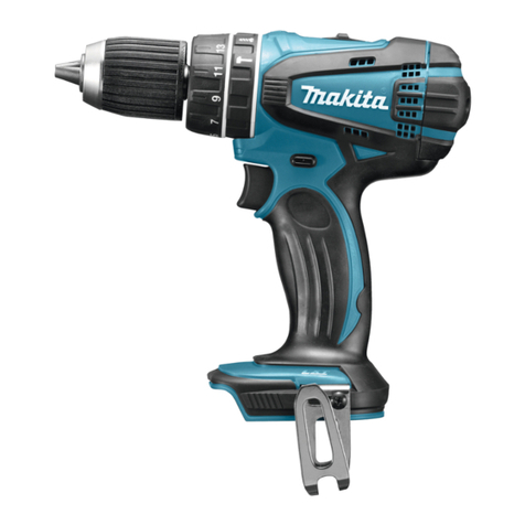
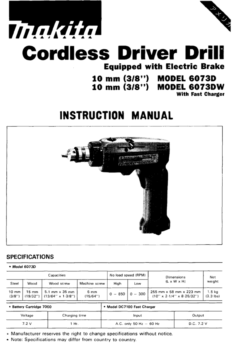
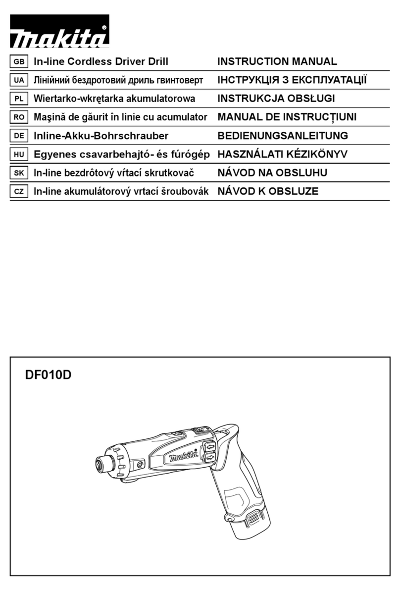
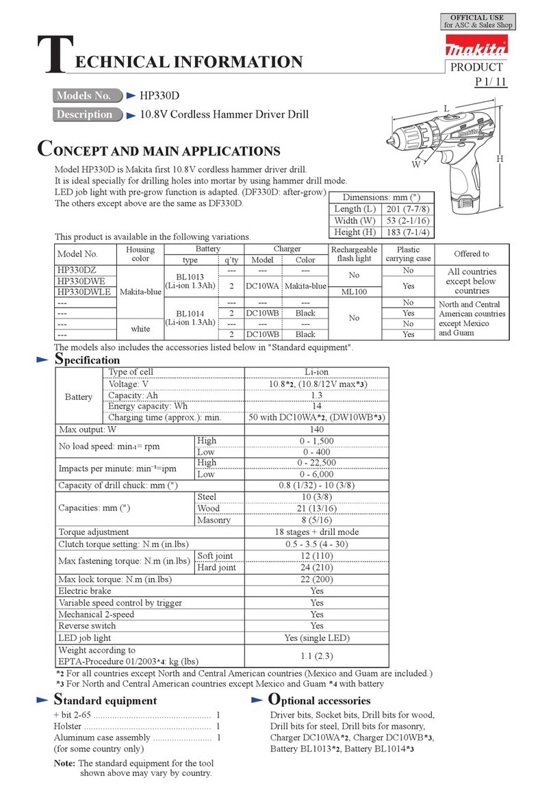
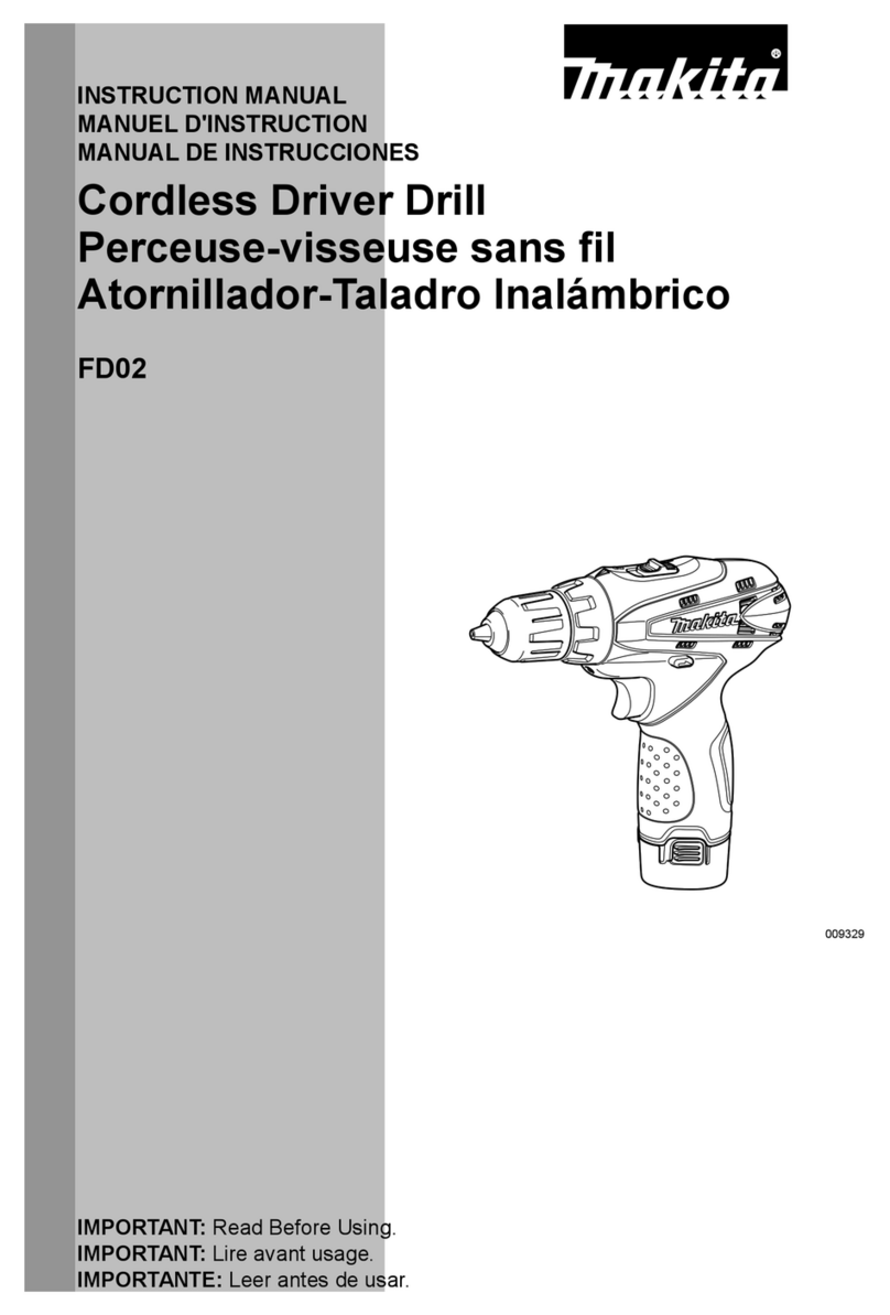
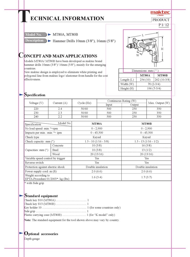
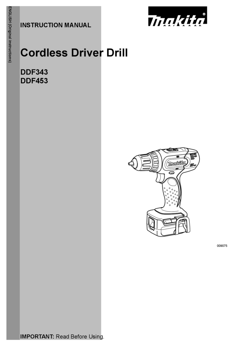
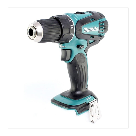
Makita 6226DW User manual

Cordless Driver Drill
Equipped with Electric Brake
9.6
V
MODEL
6226DW, 6226DWE
I2
V
MODEL
6227DW, 6227DWE
14.4
V
MODEL
6228DW, 6228DWE
With BatteryCharger
INSTRUCTION MANUAL

Capacities
Model
21mm 5.1mmx38mm 6mm
6226D
'&!?
(13/16") (13/64"
x
l-l/Z")
(1/4")
24" 5.1mmx63mm 6mm
6227D
':$?
(15/16") (13/64"
x
2-1/2")
(1/4"1
Steel
Wood
Wood
screw Machine screw
No
loadspeed
(RPM)
Overall Net
High Low length weight
0-1.100 0-350 210" 1.4kg
/min.
bin.
(8-114") (3.1
Ibs)
0-1,100 0-350
210mm
1.5kg
/min. /min. (&1/4")
(3.3
Ibs)
BatteryCartridge
I
Voltage
11
BatteryCharger
I
Input
I
Output
I
Chargingtime
24" 5.1mmx63mm 6mm 0-1,100
6228D
I
':$?
1
/15/16")
I
(13/64" x 2-1/27
I
11/4")
I
hin.
1420
I
14.47[ DC1470
I
A'C'only
D.C.
50 Hz-60HZ
I
7.2V- 14.4V
I
60min'
0-350 210mm 1.6kg
/min. 18-1/4") (3.5
Ibs)
~~
~~
Manufacturerresewes the righttochangespecificationswithout notice.
Note: Specificationsmaydiffer from country tocountry.
WARNING: Foryour personalsafety, READand understandbefore using.
SAVE THESE INSTRUCTIONSFOR FUTURE REFERENCE.
2

GENERAL
SAFETY
RULES
USA0031
(For
All
Battery Operated
Tools)
WARNING! Read and understand all instructions.
Failure
to
follow
all instructions listed
below,
may result
in
electric
shock,
fire and/or serious personal injury.
SAVE THESE INSTRUCTIONS
Work Area
1.
Keep your work area cleanandwell
lit.
Cluttered benchesand dark areas invite
accidents.
2.
Do
notoperatepowertools
in
explosiveatmospheres, suchas
in
the presence
of flammable liquids, gases,
or
dust. Power tools create sparks which may
ignite the dust or fumes.
3.
Keep bystanders, children, and visitors away while operating a power tool.
Distractions can cause you to lose control.
Electrical Safety
4.
A battery operated tool with integral batteries or a separate battery pack
must berechargedonly withthe specified chargerfor the battery.
A
charger
that may be suitable for one type of battery may create
a
risk
of
fire when
used with another battery.
5.
Use battery operated tool only with specifically designated battery pack.
Use of any other batteries may create a risk
of
fire.
Personal Safety
6.
Stayalert, watch what youaredoing, andusecommon sense whenoperating
a power tool.
Do
not use tool while tired or under the influence of drugs,
alcohol, or medication.
A
moment
of
inattentionwhile operating powertools
may result in serious personal injury.
7.
Dressproperly.
Do
notwear loose clothingorjewelry. Containlonghair. Keep
your hair, clothing, andglovesaway from movingparts. Loose clothes, jewelry,
or long hair can be caught in moving parts.
8.
Avoidaccidentalstarting. Be sure switch is
in
the lockedor off positionbefore
inserting battery pack. Carrying tools with your finger on the switch or
inserting the battery pack into a tool with the switch.on invites accidents.
9.
Remove adjusting keys or wrenches before turning the tool on.
A
wrench
or a key that is left attachedto arotatingpartof the tool may result inpersonal
injury.
IO.
Do
notoverreach. Keep properfooting andbalanceatalltimes. Proper footing
and balance enable better control of the tool in unexpected situations.
11.
Use safety equipment. Always wear eye protection. Dust mask, non-skid
safety shoes, hard hat, or hearing protection must be used for appropriate
conditions.
3

Tool
Use
and
Care
12.
Use clamps or other practical way tosecure and support the workpiece to
a stable platform. Holdingthe work by hand or against your body is unstable
and may lead to
loss
of control.
13.Do not force tool. Usethe correct tool for your application. The correct tool
will do the job better and safer at the rate for which
it
is designed.
14.
Do not use tool
if
switch does not turn
it
on or off.
A
tool that cannot be
controlled
with
the switch is dangerous and must be repaired.
15.Disconnect battery pack from tool
or
place the switch
in
the locked or off
position before making any adjustments, changing accessories,
or
storing
the tool. Such preventive safety measures reducethe risk of startingthe tool
accidentally.
16.
Store idle tools out of reach of children and other untrained persons. Tools
are dangerous in the hands of untrained users.
17.When battery pack isnot
in
use, keep
it
away fromother metal objects like:
paper clips, coins, keys, nails, screws,
or
other small metalobjects that can
make a connection from one terminal to another. Shorting the battery
terminals together may cause sparks, burns, or a fire.
18.
Maintain tools with care. Keep cutting tools sharp and clean. Properly
maintainedtools
with
sharp cutting edge are less likely tobindand are easier
to
control.
19.
Check for misalignment
or
binding of moving parts, breakage of parts, and
any other condition that may affect the tool's operation.
If
damaged, have
the tool serviced before using. Many accidents are caused by
poorly
maintained tools.
20.
Use only accessories that are recommended by the manufacturer for your
model.Accessoriesthat may be suitable for onetool may create a risk of injury
when used on another tool.
Service
21.
Tool
service must be performed only by qualified repair personnel. Service
or maintenanceperformed byunqualified personnelmay result
in
a risk of
injury.
22.
When servicing a tool, use only identical replacement parts. Follow
instructions
in
the Maintenance section of this manual. Useof unauthorized
parts
or failure tofollow Maintenance Instructions may create a
risk
of
shock
or injury.
4

Specific Safety
Rules
USBOZZ-l
1.
Holdtool by insulatedgripping surfaceswhen performingan operationwhere
the cutting
tool
may contact hidden wiring. Contact
with
a "live" wire
will
also make exposed metal parts
of
the
tool
"live"
and
shock
the
operator.
2.
Be aware that this tool is always in an operating condition, because
it
does
not have
to
be plugged into an electrical outlet.
3.
Always be sure
you
have
a
firm footing.
4.
Be
sure no one is below when using
the
tool
in
high locations.
5.
Hold the tool firmly.
6.
Keep hands away from rotating parts.
7.
Do
not leave
the
tool running. Operate
the
tool only when hand-held.
8.
Do
not touch
the
drill bit
or
the
workpiece immediately after operation; they
may be extremely hot and could burn your skin.
SYMBOLS
The followings
show
the
symbols
used
for
tool.
v
.................................
volts
-
----
.................................
direct current
n,
.................................
noload speed
..Jmin
................................
revolutions
or
reciprocation
per
minute
5

IMPORTANT SAFETY INSTRUCTIONS
FOR
CHARGER
&
BATTERY CARTRIDGE
I.
SAVE THESE INSTRUCTIONS
-
This manual
Length of Cord (Feet)
25
AWG Size of Cord
18
contains important safety and operating instructions for battery charger.
2.
Beforeusingbattery charger, read all instructionsand cautionary markings
on
(1)
battery charger,
(2)
battery, and
(3)
product using battery.
3.
CAUTION
-
To reduce risk of injury, charge only MAKITA rechargeable
batteries marked on the charger label. Other types of batteries may burst
causing personal injury and damage.
4.
Do not expose charger to rain or snow.
5.
Use of an attachment not recommended or sold by the battery charger
manufacturer may result
in
ariskof fire, electric shock, or injury topersons.
6.
To reduce risk of damage toelectric plugand cord, pull by plug rather than
cord when disconnecting charger.
7.
Make sure cord islocated
so
that
it
will not be stepped on, tripped over, or
otherwise subjected to damage or stress.
8.
Anextension cord should not be used unless absolutely necessary.
Use
of
improper extension cord could result
in
a risk of fire and electric shock.
If
extension cord must be used, make sure:
a. That pinsonplugof extension cordarethe same number, size, andshape
b. That extensioncordisproperlywired and
in
goodelectricalcondition; and
c. That wire size isat least as largeas the one specified
in
the table below.
as those of plug on charger;
50
100 150
18 18 16
TABLE
1
RECOMMENDED MINIMUM AWG SIZE
FOR
EXTENSION CORDS FOR BATTERY CHARGERS
9.
Do
not operate charger with damaged cord or plug
-
replace
mediately. them im-
IO.
Donotoperatecharger
if
it
hasreceivedasharpblow, beendropped, or other-
wise damaged
in
any way; take
it
to a qualified serviceman.
11.
Do not disassemble charger or battery cartridge; take
it
to
a
qualified
serviceman when service or repair is required. Incorrect reassembly may
result
in
a risk of electric shock or fire.
12.
To
reducerisk of electric shock, unplug chargerfromoutlet before attempt-
ingany maintenanceor cleaning. Turning
off
controls willnotreducethis risk.
6

ADDITIONAL SAFETY RULES
FOR CHARGER
&
BATTERY CARTRIDGE
USCOOl-
1
1.
Do
not charge Battery Cartridge when temperature is
BELOW
10°C
(5OOF)
2.
Do
not attempt touse astep-uptransformer, anenginegeneratoror
DC
power
3.
Do
not allow anything to cover or clog the charger vents.
4.
Always cover the battery terminals with the battery cover when the battery
5.
A
battery short can cause a large current flow, overheating, possible burns
or ABOVE 4OoC
(104OF).
receptacle.
cartridge is not used.
and even a breakdown.
(1)
Do
not touch
the
terminals with any conductive material.
(2)
Avoidstoringbattery cartridgeinacontainerwithother metalobjectssuch
(3)
Do
not expose battery cartridge to water or rain.
ture may reach or exceed 5OoC (122OF).
completely worn out. The battery cartridge can explode
in
a fire.
as nails, coins, etc.
6.
Do
not store the tool and Battery Cartridge
in
locations where
the
tempera-
7.
Do
not incinerate the Battery Cartridge even
if
it
is severely damaged or is
SAVE THESE INSTRUCTIONS.
7

FUNCTIONALDESCRIPTION
Installingor removingbattery
cartridge
*Always switch off the tool before inser-
tionor removalof the batterycartridge.
*To
remove the battery cartridge, with-
draw it from the tool while pressing the
buttonson bothsides
of
the cartridge.
*To
insert the battery cartridge, align the
tongue on the battery cartridge with the
groove in the housing and sliD it into
Battery
cartridge
'e
place. Always insert it
all
the way until it locks in place with
a
little click. If not,
it
may
accidentallyfall out
of
the tool, causing injurytoyouor someonearoundyou.
Do
not use force when insertingthe battery cartridge. If the cartridge does not slide in
easily,
it
isnot beinginsertedcorrectly.
Charging
Plug the battery charger into your power
source.
*Insert the battery cartridge
so
that the
plus and minus terminals on the battery
cartridge are on the same sides as their
respective markings on the battery
charger. Insert the cartridge fully into the
port
so,
that
it
rests on the charger port
floor.
charging will begin.
When the battery cartridge is inserted, the charging light color will flash in red color and
Whencharging iscompleted, the charging light goes out.
If you leavethe battery cartridge inthe charger after the chargingcycle is complete, the
*After charging, remove the battery cartridge from the charger and unplug the charger
CAUTION:
*The battery charger is for charging Makita battery cartridge. Never use it for other pur-
poses or for other manufacture'sbatteries.
Whenyou charge
a
new batterycartridgeor
a
batterycartridgewhich has notbeenused
for
a
long periodof time,
it
may not accept a full charge. This is
a
normalconditionand
does not indicate
a
problem.
You
can rechargethe batterycartridgefully afterdischarging
it
completely and rechargingacoupleof times.
When you charge
a
battery cartridge from
a
just-operated tool or
a
battery cartridge
which has been left in
a
locationexposedto direct sunlight or heat for
a
longtime,
let
it
cooloff. Then reinsert itand try to charge it once more.
Whenyou charge
a
newbatterycartridgeor
a
batterycartridgewhich has notbeen used
for
a
long period, sometimes the charging light will go out soon. If this occurs, remove
the batterycartridgeand reinsert
it.
If the charging light goes out within one minuteeven
after repeatingthis procedure
a
coupleof times, the battery cartridge is dead. Replace
it
with
a
newone.
charger will switch into its "trickle charge (maintenancecharge)" mode.
from the power source.
8

Trickle charge (Maintenancecharge)
If
you leave the battery cartridge in the charger to prevent spontaneous discharging after
fullcharge, the charger will switch into its "trickle charge (maintenancecharge)" mode and
keepthe battery cartridgefreshand fully charged.
Tipsfor maintaining maximumbatterylife
1.
Charge the battery cartridgebefore completelydischarged.
Always stop tooloperation and charge the battery cartridgewhen
you
notice less tool
power.
2.
Never recharge
a
fully
chargedbatterycartridge.
Overcharging shortensthe batteryservicelife.
3.
Charge the batterycartridgewith room temperatureat 10°C
-
40°C
(50°F
-
104°F)
Let
a
hot batterycartridgecooldownbeforecharging it.
Switchaction
CAUTION:
Before inserting the battery cartridge into
the tool, always check to see that the
switchtrigger actuates properlyand returns
to the
"OFF"
positionwhen released.
To start the tool, simply pull the trigger.
Tool speed is increased by increasingpres-
sure on the trigger. Release the trigger to
stop.
Reversingswitch action
CAUTION:
*Always check thedirectionof rotation before operation.
*Use the reversing switch only after the tool comes to
a
complete stop. Changing the
directionof rotationbeforethe tool stops may damage the tool.
*When not operating the tool, always set
the reversing switch lever to the neutral
position.
This tool has
a
reversing switch to change
the direction of rotation. Depress the
reversing switch lever from the A side for
clockwise rotation or from the B side for
counterclockwiserotation.When the switch
lever is in the neutral position, the switch
trigger cannot be pulled.
Reversingswitchlever
77
1
Clockwise Counterclockwise
9

Speedchange
To change the speed, first switch off the
tool and then slide the speed change lever
to the
"11"
side for high speed or
"I"
side
for low speed. Be sure that the speed
change lever is set to the correct position
before operation. Use the right speed for
your job.
Low
speed
High speed
Speed
change lever
I
CAUTION:
*Always set the speed change lever fully to the correct position. If you operate the tool
withthe speed change lever positionedhalf-way betweenthe
"I"
side and
"11"
side,the
tool may be damaged.
Do
not use the speedchange leverwhile the toolis running.The toolmay be damaged.
Adjustingthe fasteningtorque
The fasteningtorque can be adjustedin
17
steps by turning the adjusting ring
so
that
its graduations are alignedwith the pointer
on the tool body. The fastening torque is
minimum when the number
1
is aligned
with the pointer, and maximum when the
El
marking
is
alignedwith the pointer.
The clutch will slip
at
various torque levels
when set at the number
1
to
16.
The clutch
is designednot to slip at the
fl
marking.
Before actualoperation, drive
a
trial screw
into your material or
a
piece of duplicate
materialto determinewhich torque levelis
I
Adjusting ring
Drillmarking
Pointer
Graduations Adjusting ring
Drillmarking
Pointer
Graduations
piredfor
a
particularapplication.piredfor
a
particularapplication.
NOTE:
*Do
not operate the tool with the adjusting ring set between the number
16
and the
B
marking. The toolmay be damaged.
10

ASSEMBLY
Installingor removingdriver bitor drill bit
CAUTION:
Always be sure that the tool is switched off and the battery cartridge is removedbefore
installingor removingthe bit.
Hold the ring and turn the sleeve counter-
clockwise to open the chuck jaws. Place
the bit inthe chuck as far as it willgo. Hold
the ring firmly and turn the sleeve clock-
wise
to
tightenthe chuck.
To
remove the bit, hold the ring and turn
the sleevecounterclockwise.
11

OPERATION
Nominaldiameter
of
md
screw
(mml
Screwdrivingoperation
Place the point of the driver bit in the
screw head and apply pressureto the tool.
Start the tool slowly and then increase the
speed gradually. Release the trigger
as
soon
as
the clutchcuts in.
Recommended
size
of
pilot
hole
(mml
NOTE:
*Make sure that the driver bit is insertedstraight inthe screw head,
or
the screw and/or
bit may be damaged.
3.1 (l/e")
3.5
(W'I
3.8
15/32")
4.5
(11M'I
4.8
(3/16")
5.1 (13,"')
5.5(7/32"l
5.8
(7/32"1
6.1(15M"I
*When driving wood screws, predrill pilot
holes to make driving easier and to pre-
vent splitting of the workpiece. See the
chart.
2.0-
2.2
(5/64"
-
3/32")
2.3
-
2.513/32''
-
3/32'?
2.5-
2.8
13/32"
-
7/61',)
2.9
-
3.2
(7B-I"
-
1W'I
3.1
-
3.4
(1W'-
9/64")
3.3
-
3.6
(1W'
-
9/64")
3.7
-
3.9(9/4"
-
5/32"]
4.0-4.2
W32"
-
11/64")
4.2-4.4(11/64"- 11/61")
*If
the tool is operated continuously untilthe battery cartridge has discharged, allow the
toolto rest for
15
minutesbeforeproceedingwith
a
fresh battery.
Drillingoperation
First, turn the adjusting ring
so
that the pointer on the tool body points to the
8
marking.
Then proceedas follows.
*Drilling inwood
When drilling in wood, best resultsare obtained with wood drills equippedwith
a
guide
screw. The guide screw makes drillingeasier by pullingthe bit into the workpiece.
To
preventthe bitfrom slippingwhen starting
a
hole, make an indentationwith
a
center-
punch and hammer
at
the point to be drilled. Place the point of the bit inthe indentation
and start drilling.
Use
a
cutting lubricant when drilling metals. The exceptions are iron and brass which
should be drilleddry.
*Drilling inmetal
12

CAUTION:
*Pressingexcessively
on
the tool will not speed upthe drilling.
In
fact, this excessivepres-
sure will only serve to damage the tip
of
your bit, decrease the tool performanceand
shortenthe service life
of
the tool.
*There is
a
tremendous force exerted on the tool/bit at the time
of
hole breakthrough.
Holdthe
tool
firmly and exertcarewhen the
bit
beginsto break through the workpiece.
*A stuck bit can be removedsimply by setting the reversingswitch to reverserotation in
order to back out. However,the tool may back out abruptly
if
you
do
not holdit
firmly.
*Always securesmallworkpiecesin
a
vise or similar hold-downdevice.
*If the tool is operatedcontinuously until the battery cartridge has discharged, allow the
tool to restfor 15minutes before proceedingwith afresh battery.
Installingset plate
For
6226D
&
6227D
Always installthe set plate when usingbat-
tery cartridges 9100, 9102, 9102A for
6226D and 1200, 1202, 1202A for 6227D.
Install the set plate on the tool with the
screw provided.
Screw
I
13

MAINTENANCE
CAUTION:
Always be sure that the tool is switched
off
and the battery cartridge
is
removed before
attempting
to
performinspection or maintenance.
To
maintainproductSAFETY and RELIABILITY, repairs, maintenance or adjustment should
be performed by Makita Authorized or Factory Service Centers, always using Makit
replacementparts.
Recycling the Battery
The
only
way to dispose
of
a Makita battery is
to recycle it. The law prohibits any other
method
of
disposal.
@
Ni-Cd
To
recycle the battery:
1.
Remove the battery from the tool.
2.
a). Take the battery
to
your nearest Makita Factory Service Center
or
b). Take the battery
to
your nearest Makita Authorized Service Center or
Distributor that has been designated as a Makita battery recycling location.
Call your nearest Makita Service Center or Distributor to determine the location
that provides Makita battery recycling. See your local Yellow Pages under
"Tools-Electric'
14

ACCESSORIES
CAUTION:
These accessories or attachments are recommended for use with your Makita tool specified
in
this
manual. The use of any other accessories or attachments might present a risk of injury
to
persons.
The accessories or attachments should beusedonly
in
the proper and intended manner.
784201-5
784202-3
784203-1
784206-5
784207-3
Bits
No.
1 65(2-5B"l
45 (1-3/4")
No.
2 65 (2-5/8"1
11014-3/8")
150(4-7/8")
I
Size
I
Part~o
711021-A 1/2"
Phillips
e=€m
3/8"
I
3-518''
Slotted
Square drill bit 7846064A
711OOOA-A
Phillipsbit
Part~o.
I
Size
I
L
(mm)
6pc. set: 1/16". 1/8", 3/16". 1/4"
5/16".
3B"
Bestselling bitsin
Drillbits
Tested best inMakitadriverdrills for smooth fast
drillingand more holesper battery change.
Highspeedsteel. For drillingin metal,
wood
and
plastic.Jobberslength. Specialsurfacetreatment
for lubricitygives smoother drilling.
-
5/32"
Overall
length
1-718"
2-1/4"
2-3/4"
3-1/8"
3-1/2"
3-3/4"
4"
4-1/4"
4-1/2"
4-3i4"
5"
Double-endedPhillips
I
Slottedbit
1-3/4" long Part
No.
7846144
2-112"
long Part
No.
784613-A
Rubber padassembly
Part
No.
123001-2
Foam polishingpad
Part
No.
743023-2
-
Wool
bonnet
Part
No.
7434016
Battery
cover
Part
No.
414938-7
I
convenientcase.
15

Batterycharger
Model DC9710
ModelDC1470
Highcapacitybattery charger
ModelDC1411
Batterycartridge9120 I9122I9134I9135 Batterycartridge1420
I
1422
I
1434
I
1435
Batterycartridge1220
I
1222
1
1234
I
1235
Set
plate
Plasticcarryingcase
16

Oec.-08-'99
US
CORDLESS DRIVER DRILL
Model
6226D
Model
6227D
Model
6228D
Note: The switch and other part configurations
may differ from country to country.
17

MOOEL
82280, 62270. 62280
4
5
'i\M
$.fD
DESCRIPTION
11
21
31
8
9
1
61
71
81
91
Dac.-O8-'99
US
""df
&
DESCRIPTION
io
11
12
13
14
16
16
17
18
19
20
MACHINE
1
1
1
1
1
1
1
2
1
1
1
Speed
Change
Lever
Assembly
Housing
Set
IWilh
llem
20)
Name
Plats
Tapping
Screw
Bind
PT
3x16
For
Modal
62260.
6227D
For
Modal
62280
Pan
Head
Screw
Max22
For
Model
8226D.
62271)
Leal
Spring
FIR
Chanea
Lever
Switch
1
Pan Head
Screw
M3x6
MACHINE
'
Holder
Spring Terminal
It)
Spring
Termma1
1-1
Pan
Head
Screw M4522
Keyless
Drill
Chuck
10
GEAR
ASSEMBLY
DC
Motor
Pan
Head
Screw
M3x6
Heat
Sink
Mskila
Label
Housing
Set
(With item
21
Note: The switch
and
other
pan
specificationsmay dillsr
from
country 10 country
18

-
MAKITA
LIMITED
ONE
YEAR WARRAHTY
Warranty
Policy
Every Makita
tool
is
thorou ly ins ected and tested before
leaving
the factory.
It
is
warranted
to
be free of defects from workdand matchla for the period of ONE YEAR
from
the date
of
original
urchasc. Should any troubl develop
during
this
oneyepr period, return the COMPLETE
tool. frebtprepaid, to one of Makita’s Factory
or
Authorized ServiceCenters.
If
inspection shows
the trouble
is
caused by defective workmanship
or
material, Maklta
will
rep&
(or
at
our
option,
replace) without charge.
ThisWarranty does
not
apply where:
8
repairshave
been
made
or
attempted by others:
0
repain are required
becpuw
of
normal
wear and tear:
0
The
tool
hm
been
abused, misused
or
improperly maintained
;
0
alterationshave bcan made
to
the
tool.
IN
NO
EVENT
SHALL
MAKITA
BE
LIABLE
FOR
ANY
INDIRECT,
INCIDENTAL
OR
CON-
SEQUENTIALDAMAGES FROM THE SALE OR
USE
OF
THE PRODUCT. THIS DISCLAIMER
APPLIESBOTH DURINGAND AFTER THE TERM OF
THIS
WARRANTY.
I
MAKlTA DISCLAIMS LIABILITY FOR ANY IMPLIED WARRANTIES, INCLUDING IMPLIED
WARRANTIES OF “MERCHANTABILITY”
AND
“FITNESS FOR A SPECIFIC PURPOSE,”
AFTER THE ONE-YEAR TERM OF
THIS
WARRANTY.
This
Warranty
gives
you speeinclegal
rightr,
and you may
also
have other rights which vary from
state to state. Some states do
not
allow theexclusion
or
Limitation
of
incidental
or
consequential
damagca.
so
the above limitation
or
sxcluaion may
not
apply
to
you.
Some
states
do
not allow
limitation
on
how
long
an
implied warranty
Imts,
$0
the abovelimitationmay
not
apply
to
you.
-
Makita Corporation
3-11
-8,
Sumiyoshi-cho,
Anjo, Aichi
446-8502
Japan
884293-067 PRINTED
IN
JAPAN
1-9
-
12
-
N
Other manuals for 6226DW
2
This manual suits for next models
5
Table of contents
Other Makita Drill manuals

Makita
Makita BHR242 Manual

Makita
Makita DHP484 User manual

Makita
Makita LXPH03 1 Series Manual

Makita
Makita DDF480Z User manual

Makita
Makita HP332D User manual

Makita
Makita 8406 User manual

Makita
Makita HP002G User manual

Makita
Makita HP347D User manual

Makita
Makita DS4012 User manual

Makita
Makita M8103 User manual
Popular Drill manuals by other brands

Narex
Narex EVP 16 K-2 Original operating manual

Rongpeng
Rongpeng RP7101 instruction manual

Truper
Truper ROTO-1/2A7-2 manual

Central Machinery
Central Machinery 44846 Assembly and operating instructions

Campbell Hausfeld
Campbell Hausfeld DG111800CD Operating instructions and parts manual

Sealey
Sealey CP1201 manual