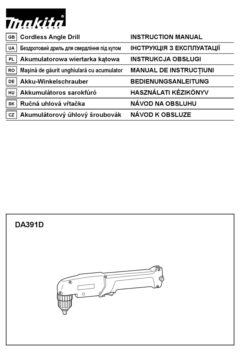
Makita DA4000LR User manual

Angle
Drill
Drilling capacities
Steel Wood
I
13
mm
W2")
MODEL
DA4000LR
Variable speed
/
Reversing
Noloadspeed
(RPM)
Overalllength Netweight
High
Low
I
INSTRUCTION MANUAL
3.7 kg
13 mm 38 mm 413 mm
(1/2
")
1
(1-1/2")
1
O-gOO'min'
1
0-400/min'
1
(16-1/4")
1
(8.1
Ibs)
Manufacturerreservesthe right tochange specifications without notice.
Note: Specifications may differ from country tocountry.
WARNING: For your personalsafety, READand UNDERSTANDbefore using.
SAVE THESE INSTRUCTIONSFOR FUTURE REFERENCE.

GENERAL SAFETY RULES
USA0021
(For
All
Tools)
WARNING!
Read and understand all instructions. Failure
tofollow all instructions listedbelow, may result inelectric
shock, fire and/or serious personal injury.
SAVE
THESE INSTRUCTIONS
Work Area
1.
Keepyour work area cleanand well
lit.
Clutteredbenches and dark areas invite
accidents.
2.
Do not operate power tools
in
explosiveatmospheres, such as
in
the presence
of flammable liquids, gases, or dust. Power tools create sparks which may
ignite the dust or fumes.
3.
Keep bystanders, children, and visitors away while operating a power tool.
Distractions can cause you to lose control.
Electrical Safety
4.
Double Insulatedtools are equipped with a polarized plug (onebladeis wider
than the other.) This plug will
fit in
a polarized outlet only one way. If the
plug does not fit fully
in
the outlet, reverse the plug.
If
it
still does not fit,
contact a qualified electrician to install a polarized outlet. Do not change
the plug in any way. Double insulation
E3
eliminates the need for the three
wire grounded power cord and grounded power supply system.
5.
Avoid body contact with grounded surfaces such as pipes, radiators, ranges
and refrigerators. There is an increased risk of electric shock if your body is
grounded.
6.
DonotexDose Dower tools torainor wet conditions.
Water
entering a Dower
-.
tool
will
increase the risk of electric shock.
Do not abuse the cord. Never use the cordtocarry the tools or pullthe plug
from an outlet. Keep cordaway from heat,
oil,
sharp edges or movingparts.
Replace damaged cords immediately. Damaged cords increase the risk of
electric shock.
When operating a power tool outside, use an outdoor extension cord marked
"W-A" or "W." These cords are rated for outdoor use and reduce the risk
of
electric shock.
Personal Safety
9.
Stay alert, watch what you are doingandusecommon sense when operating
a power tool.
Do
not use tool while tired or under the influence of drugs,
alcohol, or medication.
A
moment of inattentionwhile operating power tools
may result
in
serious personal injury.
IO.
Dress properly. Donotwear loose clothing orjewelry. Contain longhair. Keep
your hair, clothing, andglovesaway from movingparts. Loose clothes, jewelry
or long hair can be caught
in
moving parts.
2

11.
Avoid accidental starting. Be sure switch is off before plugging
in.
Carrying
tools withyour finger onthe switch or plugging in
tools
that have the switch
on invites accidents.
12.
Remove adjusting keys or wrenches before turning the tool on.
A
wrench
or
a
key that
is
left attached toa rotatingpart
of
thetool may result inpersonal
injury.
13.
Do
notoverreach.Keepproper footingand balanceatalltimes. Proper footing
and balance enables better control of the tool in unexpected situations.
14.
Use safety equipment. Always wear eye protection. Dust mask, non-skid
safety shoes, hard hat, or hearing protection must be used for appropriate
conditions.
Tool
Use and Care
15.
Use clamps or other practical way tosecure and support the workpiece to
a stable platform. Holding the work by hand or against your body is unstable
and may lead to
loss
of control.
16.
Do
notforce tool. Use the correct tool for your application. The correct tool
will
do the job better and safer at the rate for which
it
is
designed.
17.
Do
not use tool
if
switch does not turn
it
on or off. Any tool that cannot
be controlled with the switch is dangerous and must be repaired.
18.
Disconnect the plugfrom the power source before making any adjustments,
changing accessories, or storing the tool. Such preventive safety measures
reduce the risk of starting the tool accidentally.
19.
Store idle tools out of reach of children and other untrained persons. Tools
are dangerous in the hands of untrained users.
20.
Maintain tools with care. Keep cutting tools sharp and clean. Properly
maintained tools, with sharp cuttingedges are less likely to bind and are easier
to control.
21.
Check for misalignment or binding of moving parts, breakage of parts, and
any other condition that may affect the tools operation. If damaged, have
the tool serviced before using. Many accidents are caused by poorly
maintained tools.
22. Use only accessories that are recommended by the manufacturer for your
model. Accessories that may be suitable for one tool, may become hazardous
when used on another
tool.
SERVICE
23.
Tool
service must be performed only by qualified repair personnel.
Service
or maintenance performed by unqualified personnel could result in a risk of
injury.
24.
When servicing a tool, use only identical replacement parts. Follow
instructions
in
the Maintenancesection of this manual. Use
of
unauthorized
parts or failure tofollow Maintenance Instructions may create
a
risk of electric
shock or injury.
3

USBOOl
1
Specific
Safety
Rules
1.
Holdtool by insulatedgrippingsurfaces when performingan operation+where
the cutting tools may contact hidden wiring or its own cord. Contact
with
a "live" wire
will
make exposed metal parts
of
the tool "live" and shock the
operator.
Be sure no one is below when using the tool in high locations.
2.
Always be sure you have a firm footing.
3.
Hold the tool firmly.
4.
Keep hands away from rotating parts.
5.
Do
not leave the tool running. Operate the tool only when hand-held.
6.
Do
nottouch the drill bitor the workpiece immediately after operation; they
may be extremely hot and could burn your skin.
SAVE
THESE
INSTRUCTIONS.
4

SYMBOLS
The followings show the symbols used for tool.
v
....................................
volts
A
....................................
amperes
Hz
....................................
herts
%
....................................
alternating current
rb
....................................
no
load speed
....................................
Class
II
Construction
..Jmin
...................................
revolutions or reciprocation per minute
5

FUNCTIONAL
DESCRIPTION
Switch action
CAUTION:
Before plugging inthe tool, always check to see that the switchtrigger actuates properly
and returnsto the
"OFF"
positionwhen released.
To
start the tool, simply pull the trigger.
Tool
speed is increased by.increasing pres-
sure on the trigger. Release the trigger to
stop.
trigger
Reversingswitch action
CAUTION:
*Always check the direction of rotationbeforeoperation.
.Use the reversing switch only after the tool comes to
a
complete stop. Changing the
direction of rotationbeforethe tool stops may damagethe tool.
This tool has
a
reversing switch to change
the direction
of
rotation. Move the revers-
ing switch lever to the A side for clockwise
rotation or the B side for counterclockwise
rotation.
TReversiy
switch
lever
6

ASSEMBLY
CAUTIO
N
:
Always be sure that the tool is switched
off
and unpluggedbefore installing or removing
angle attachment, side grip, bit or other accessories.
I
I
Installingor removingdrill bit
To
installthe bit, place it inthe chuck as far
as it will go. Tighten the chuck by hand.
Place the chuck key in each of the three
holes and tighten clockwise. Be sure to
tighten allthree chuck holes evenly.
To remove the bit, turn the chuck key
counterclockwise in just one hole, then
loosenthe chuck by hand.
After usingthe chuck key, be sure to return
it
to the original position.
Installingor removingangle attachment
CAUTION:
Always be surethat the tool
is
switched off and pluggedbefore installing or removing the
angle attachment.
The angle headhas
a
spindle oneach end.
For higher speed operation, attach the drill
chuck to the end marked “HIGH”. The
higher speed is better suited for drilling
smaller diameter holes.
For lower speed operation, attach the drill
chuck to the end marked
”LOW”.
The
lower speed isbest utilizedfor drilling larger
diameter holes.
The tool is facton/ assembled with the
chuck on spindle end marked ”HIGH”.
To change to the
“LOW”
speed, proceed
as
follows:
To remove the drill chuck, first open the
chuck jaws completely and placethe chuck
key inone of the key holes.
r
1
HIGH
LOW
Drill
chuck
U
I

Remove the chuck remaining bolt through
the chuck opening by turning
it
counter-
clockwise with the hex wrench.
CAUTION:
The drill chuck and the bolt are assembled
each other. Turn the bolt counterclockwise
about
10
times
so
that they can be
removedtogether.
Loosen the bolts of the joint
by
the hex
wrench and remove the angle housing,the
joint and the socket.
To
install the socket and the joint, fit the
socket to the spindle
so
that the two faces
are fitted perfectly. Then install the joint.
For higher speed operation, fit the angle
housing marked
"LOW"
to the joint.
For lower speed operation, fit the angle
housingmarked
"HIGH"
to the joint.
Loosen
r
Angle housing
Angle housing Joint Socket
For
higherspeedoperation
8

Rotate the angle housing to the desired
position. Tighten the bolt with the hex
wrench firmly. And retighten the another
boltfirmly again.
CAUTION:
Be sure
to
tighten the two bolts firmly, or
it
may present
a
risk of injury to persons.
Slide the drill chuck to the spindle
so
that
the two faces are fitted perfectly. Holding
the drill chuck with the chuck key, tighten
the bolt (for installing the drill chuck) clock-
wise the hex wrench firmly.
r
Drill
chuck
The tool may be converted to
a
conven-
tional straight drive drill by installingthe drill
chuck without the angle attachment.
Spindle
9

Sidegrip (auxiliaryhandle)
CAUTION:
*Always be sure that the tool is switched off and unpluggedbefore installing or removing
*Always use the side grip and holdit with both hands to ensure operating safety.
the side grip.
Use of
it
without angle attachment:
Screw the side handle for the tool on the
tool barrel securely. The side grip can be
installedon either side of the tool, which-
ever isconvenient.
Use of itwith angle attachment:
Screw the side grip for the angle attach-
ment on the angle housing. Then tighten
the side grip by turning clockwise at the
desired position.
10

OPERATION
Drilling
operation
*Drillinginwood
When drilling in wood, best results are obtained with wood drills equippedwith
a
guide
screw. The guide screw makes drilling easier by pullingthe bit into the workpiece.
To
preventthe bitfrom slipping when starting
a
hole, makean indentation with
a
center-
punchand hammer
at
the point to be drilled. Place the point
of
the bit in the indentation
and
start
drilling.
Use
a
cutting lubricant when drilling metals. The exceptions are iron and brass which
should be drilled dry.
*Drilling in metal
Holding
tool
When drilling
a
large hole with
a
hole saw, etc., the side grip (auxiliaryhandle) should be
usedas
a
brace
to
maintainsafe control of the tool.
CAUTIO
N
:
*Pressing excessively on the tool
will
not speed up the drilling. In fact. this excessive
pressurewill only serve to damage the tip
of
your bit, decreasethe toolperformanceand
shorten the service lifeof the tool.
*There is
a
tremendous force exerted on the tool/bit at the time of hole breakthrough.
Holdthe tool firmly andexert care when the bit beginsto breakthrough the workpiece.
*Always grip the small workpiece firmly with
a
vise or
a
holding means.
*A stuck bit can be removedsimply by setting the reversing switch to reverse rotation in
order to back out. However, the toolwill pullaway easily unlessyou hold it firmly before
startingthe tool.
11

MAINTENANCE
CAUTION:
Always be sure that the tool is switched off and unpluggedbefore attempting to perform
inspectionor maintenance.
Replacingcarbon brushes
Remove and check the carbon brushes
regularly. Replace when they wear downto
the limit mark. Keep the carbon brushes
clean and free to slip in the holders. Both
carbon brushes should be replaced
at
the
same time. Use only identical carbon
brushes.
Limit mark
Use
a
screwdriver to remove the brush
I
holder caps. Take out the worn carbon
brushes, insert the new ones and secure
Brush
holder cap
To
maintainproduct SAFETY and RELIABILITY, repairs, maintenanceor adjustmentshould
be performed by Makita Authorized or Factory Service Centers, always using Makita
replacementparts.
12

ACCESSORIES
CAUTION:
These accessories or attachments are recommendedfor use with your Makitatool specified
in
this
manual. The use
of
any other accessories or attachments might present
a
risk
of
injuryto persons.
The accessories or attachments shouldbe usedonly in the proper and intended manner.
-
Chuck key
Hex wrench
Side grip
(Forangle attachment)
Side grip
(Forthe
tool
barrel)
-
Extensionattachment
-
Depthgauge assembly
B-
e
Plastic carrying case
13

WARNING
Some dust created by power sanding, sawing, grinding, drilling, and other
constructionactivitiescontains chemicalsknown
[to
the Stateof Califomia]
to
cause cancer, birth defects or other reproductive harm. Some examples of
these chemicals are:
*
Leadfrom lead-based paints,
Crystallinesilica from bricks and cement and other masonry products, and
Arsenic andchromiumfrom chemically-treatedlumber.
Your risk from these exposures varies, depending on how often you do this
type of work.
To
reduce your exposure
to
these chemicals: work in a well
.ventilated area, and work with approved safety equipment, such as those
dust masksthat are specially designed
to
filter out microscopicparticles.
MAKITA LIMITEDONE YEAR WARRANTY
Warranty
Policy
I-very Makita tool is thoroughly inspected and tested before leaving the factory.
It
is warranted to
be iree of defects irom worhanshipand materials for the period of ONE YIAR from the date of
orignal purchase Should any trouble develop during this one-year period. return the COMPLETt
tool,
freight prepaid,
IO
one
of
Makita’s Factory or Authorized Service Centers.
If
inspection showr
the trouble is caused by defective workmanship or matenal. Makita will repair (or at our optlon,
replace) without charge.
This Warranty does not apply where:
8
repairs have been made
or
attempted by others.
8
repairs are required because of normal wear and tear
8
The tool has been abused, misused or improperly maintalned.
8
alterationshave been made to the
tool.
IN
NO tVFNT SHALL MAKITA
BE
LlABLt
tOR
ANY INDIRtCT, INClDtNTAL
OR
CON-
StQUtNTIAL DAMAGES FROM THE SALE
OR
UStOFTHtPRODUCT THIS DISCLAIMER
APPLIES BOTH bURING AND AFTER THE TFRM
OF
THIS WARRANTY
MAKITA DISCLAIMS LIABILITY FOR ANY IMPLltD WARRANTIES, INCLUDING IMPLIED
WARRANTIFS
OF
“MERCHANTABILITY” AND “FITNESS
FOR
A SPLClFlC PURPOSE.”
AFTtR THE ONE-YEAR TERM
OF
THIS WARRANTY
This Warranty gives you specific legal rights, and you may also have other nghts which vary from
state
10
state. Some states do not allow the exclusion or Limitation ofincidenlal
01
consequential
damages.
so
the above limitation or exclusion may not apply to you. Some states do not allow
limitation onhow long an implied warranty lasts,
so
the above limitation may not apply to you.
___f)
Makita Corporation
3-11
-8,
Sumiyoshi-cho,
Anjo,
Aichi,
446-8502 Japan
88439
2-065
PRINTED IN JAPAN
2001
-9-N
Other manuals for DA4000LR
12
Table of contents
Other Makita Drill manuals

Makita
Makita 6349DWDE Quick start guide

Makita
Makita DP4010 User manual

Makita
Makita BHP440 User manual

Makita
Makita M6201 User manual

Makita
Makita XFD16 User manual

Makita
Makita DS4000 User manual

Makita
Makita DF347D User manual

Makita
Makita BHR241 User manual

Makita
Makita HP2051FH User manual

Makita
Makita 6312DW User manual

Makita
Makita 6260DWPLE User manual

Makita
Makita 6402 User manual

Makita
Makita DDF486 User manual

Makita
Makita BDF450 User manual

Makita
Makita DHP487YX2B User manual

Makita
Makita DHP453T001 User manual

Makita
Makita 6313D User manual

Makita
Makita DDF482 User manual

Makita
Makita DHP343 User manual

Makita
Makita HP0300 User manual