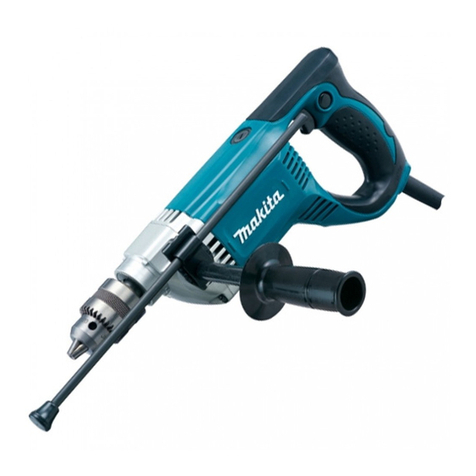
Makita HP1640F User manual

Models No.
Description
PRODUCT
TECHNICAL INFORMATION
CONCEPT AND MAIN APPLICATIONS
P 1/ 7
HP1640, HP1640F, HP1641, HP1641F
Hammer Drill 16 mm (5/8")
Models HP1640, HP1640F, HP1641, HP1641F have been developed
as the successor models to the current HP1620 series models, featuring
renewed external appearance.
Listed below are the differences among the four models.
These models are also available with plastic carrying case as “K” models;
HP1640K, HP1640FK, HP1641K, HP1641FK
Specification
Standard equipment
Optional accessories
Continuous Rating (W)
Voltage (V) Cycle (Hz) Input Output Max. Output (W)
110
120
220
230
240
6.5
6.0
3.3
3.1
3.0
50/60
50/60
50/60
50/60
50/60
680
---
680
680
680
380
380
400
400
400
500
500
600
600
600
110/ Taiwan 5.6 50/60 590 340 500
Current (A)
Dimensions: mm (")
Width (W)
Height (H)
Length (L) 303 (11-7/8)
72 (2-13/16)
222 (8-3/4)
Note: The standard equipment for the tool shown above may differ by country.
Chuck key S-13 ........................ 1 (HP1640/ HP1640F only)
Key holder ................................. 1 (HP1640/ HP1640F only)
Side grip .................................... 1
Depth gauge .............................. 1
Plastic carrying case ................. 1 (”K” models only)
Drill bits
Keyless drill chuck set
Drill chuck set
Side handle set
Type 43 drill stand
Chuck key S-13 (HP1640/ HP1640F only)
Depth gauge
Blow-out bulb
Chuck capacity: mm (")
Chuck type
Reversing switch
No load speed: min-1= rpm
Impacts per min: min-1= ipm
Capacities: mm (") Steel
Concrete
Wood
Protection against electric shock
Power supply cord: m (ft)
Net weight: kg (lbs)
*Taiwan: 5m, Argentine: 2.5m
0 - 2,800
0 - 44,800
Keyed chuck
1.5 - 13 (1/16 - 1/2)
16 (5/8)
13 (1/2)
30 (1-3/16)
Yes
LED job light No/ Yes
Yes
Double insulation
1.8 (4.0)
2.0 (6.6)*
Variable speed control by trigger
HP1640/ HP1640F
Keyless chuck
No/ Yes
HP1641/ HP1641F
W
L
HP1640/ HP1640F
H
HP1641/ HP1641F
Model No.
Specifications
Model No. LED job light
HP1640
HP1640F
HP1641
HP1641F
Keyed
Keyed
Keyless
Keyless
No
Yes
No
Yes
Drill chuck type

P 2/ 7
Repair
CAUTION: Remove the bit from the machine for safety before repair/ maintenance
in accordance with the instruction manual!
[1] NECESSARY REPAIRING TOOLS
[2] LUBRICATIONS
Code No.
1R045
1R139
1R165
1R223
1R224
1R232
1R269
1R291
1R298
1R346
Gear extractor (large)
Drill chuck extractor
Ring spring setting tool B
Torque wrench shaft 20-90N.m
Ratchet head 12.7
Pipe 30
Bearing extractor (small)
Retaining ring S and R pliers
Hex bar 10 with square socket
Center attachment for 1R045
Wrench 43781024-2
Removing Armature from Cam holder complete
Removing / Installing Drill chuck
Removing Helical gear 45
Removing / Assembling Drill chuck
Use with 1R223 when removing / installing Drill chuck
Supporting Helical gear 45 when installing
Remove Ball bearing from Armature shaft
Removing Retaining ring S-15 from Spindle
Removing / Installing Drill Chuck
Attachment for 1R045
Removing damaged Drill chuck
Description Use for
Apply Makita grease N.No.2 to the following portions designated with the black triangle to protect parts
and product from unusual abrasion.
Description Portion to lubricate
9
9
Spindle
13
13
15
15
Helical gear 45
Change lever
Portion where Ball bearing 6002LLB contacts
End where Steel ball 5.0 contacts
Gear teeth which engages Armature gear
Cam plate which contacts the that of Cam holder complete
Portion on which Steel ball 5.0 is received
Steel ball 5.0
Ball bearing 6002LLB Cam holder complete Armature
Fig. 1
Amount
a little
a little
Item No.
6 g
1.7 g

P 3/ 7
Repair
[3] DISASSEMBLY/ASSEMBLY
[3]-1. Drill chuck
DISASSEMBLING
DISASSEMBLING
1R223
1R224
Fig. 2 Fig. 3
1R298
1R139
Drill chuck
vise
1) Hold 1R298 with Drill chuck.
2) Clamp 1R139 in vise so that flats of Spindle can be fit into 14mm width groove of 1R139.
3) Turn Drill chuck counterclockwise using 1R223, 1R224 and 1R298. (Fig. 2)
Note: If Drill chuck does not work, insert the hook of 781024-2 to a hole of Drill chuck,
then turn Drill chuck counterclockwise. (Fig. 3)
Take the disassembling step in reverse.
Note: Pre-set the fastening torque of 1R223 to 34.3 up to 44.1N.m.
Change lever
(shifted to hammer
drill mode)
1R165
Spindle section
(Spindle, Compression spring 15,
Ball bearing 6002LLB, Retaining ring S-15,
Helical gear 45, Change lever, Steel ball 5.0,
Plate 19, Cam holder complete)
ASSEMBLING
14mm
[3]-2. Carbon brush, Helical gear 45, Ball bearing 6002LLB
1) Shift Change lever to Drill mode. (Fig. 4) Then separate Housing R from Housing L by removing 4x18 Tapping screws.
Carbon brushes can be removed from Brush holder unit.
2) Shift Change lever to hammer drill mode. Pick up Spindle and Change lever then pivot the Spindle section along
the arc illustrated in Fig. 5.
3) Remove Cam holder complete from Spindle section by pulling Spindle. (Fig. 6)
4) Applying 1R165 to Helical gear 45, press Spindle to remove Helical gear 45. (Fig. 7)
5) Remove Retaining ring S-15 with 1R291. Ball bearing 6002LLB and Compression
spring 15 can be removed.
Housing R
Housing L
4x18 Tapping
screw (7pcs.)
Change lever
Drill mode
Hammer drill mode
Fig. 4
Fig. 7
Fig. 5
Fig. 6
Cam
holder
complete
Spindle section except
Cam holder complete
Ball bearing 6002LLB
Spindle
Retaining
ring S-15
Compression spring 15
781014-2
hole of Drill chuck

P 4/ 7
Repair
[3] DISASSEMBLY/ASSEMBLY
ASSEMBLING
Take the disassembling step in reverse.
Also, refer to [3]-3. Armature
ASSEMBLING
1) Mount Compression spring 15 and Ball bearing 6002LLB on Spindle.
Apply a little amount of Makita grease N No. 2 to the contact portion of Spindle
and Ball bearing 6002LLB in advance. (Fig. 1)
And then fit Retaining ring S-15 into the groove of Spindle with 1R291.
2) Receiving Helical gear 45 with 1R232, press fit the Spindle into Helical gear 45.
(Fig. 11)
Note: The cam portion of Helical gear 45 has to be faced to the opposite from Ball
bearing 6002LLB side. (Fig. 12)
Do not contact the cam portion of Helical gear 45 with 1R232.
3) Install Armature ass’y into Field ass’y. And assemble the remaining parts of Spindle section to Cam holder complete.
Refer to Figs. 13, 14. Be sure to shift Change lever to Hammer drill mode.
Note: It is not required to remove Drill chuck when replacing Armature only.
1) Remove Spindle section (Refer to Fig.5) and separate Carbon brushes from Brush holder unit.
2) Remove Armature ass’y and Cam holder complete together from Housing L and Field ass’y.
Change lever, Steel ball 5.0 and Plate 19 can be removed from Cam holder complete. (Fig. 8)
3) Remove Armature ass’y from Cam holder complete with 1R045 and 1R346. (Fig. 9)
Ball bearings on drive end and commutator end can be removed with 1R269. (Fig. 10)
DISASSEMBLING
DISASSEMBLING
[3]-2. Carbon brush, Helical gear 45, Ball bearing 6002LLB (cont.)
[3]-3. Armature
Fig. 8 Fig. 9 Fig. 10
Cam holder complete
Cam holder complete
Armature ass’y
1R045
1R346
Change lever
Steel ball 5.0 1R269
Plate 19
Fig. 12
Fig. 11
cam portion of Helical gear 45Ball bearing 6002LLB
Fig. 14Fig. 13
Change lever
Change
lever
Plate 19
Slot for Plate 19
Retaining
ring S-15
Compression
spring S-15
After setting Plate 19 in place through
a slot of Cam holder complete, insert
Change lever and Steel ball 5.0 into
Cam holder complete.
Axis for
Pivoting
Put Steel ball 5.0
to the depression
on Change lever
after applying a
little bit grease
on the hole.
Viewed from the upper side Change lever
Armature ass’y
Field ass’y
Spindle
section
Spindle
Helical
gear 45
Ball bearing
6002LLB
1R232
P 5/ 7
Spindle section
Armature ass’y
Refer to 4).
Refer to 6).Housing L
Repair
[3] DISASSEMBLY/ASSEMBLY
ASSEMBLING
4) Pivot Cam holder complete on Armature shaft and install Spindle section
into Housing L while revolving Spindle clockwise in order to engage their
gear teeth. (Fig. 15)
5) Install Carbon brushes into Carbon brush holder.
6) Shift Change lever to Drill mode (Fig. 15). Then fix Housing R to Housing L
by tightening 4x18 Tapping screws (7pcs.)
ASSEMBLING
Take the disassembling step in reverse.
Note: Brush holder unit has to be mounted to Housing L so that the recess portions are faced to Switch. Refer to Fig.
D-2A and D-2B of Wiring diagram.
1) Separate Housing R and remove Carbon brushes.
2) Remove Armature ass’y and Spindle section from Field ass’y
and Housing L. (Fig. 16)
3) Disconnect receptacles of Lead wire ends from Brush holder
unit. (Fig. 17)
4) Remove the jaws of Brush holder unit from the protrusions of
Field ass’y. (Fig. 18)
5) Lever up Brush holder unit from Field ass’y with slotted
screwdriver as illustrated in Fig. 19.
Note: Joints are in the reverse side of Field ass’y, too.
Take the steps 4) and 5) in the same way.
DISASSEMBLING
[3]-3. Armature (cont.)
[3]-4. Field ass’y, Brush holder complete
Fig. 17 Fig. 18
Fig. 15
Fig. 16
Field ass’y
Housing L
Fig. 19
Brush holder unit
protrusion of
Field ass’y
jaw of Brush holder unit
Field ass’y
Connector of
Field ass’y
Connector of
Brush holder
unit
slotted screwdriver
Receptacle
Field
Brush holder unit

Circuit diagram of HP1640
Wiring diagram of HP1640
P 6/ 7
White
Noise
suppressor
Noise suppressor is not
used for some countries.
Color index of lead wires' sheath
Black
Blue
Brown
Switch
Receptacle
Receptacle
Brush holder unit
Power supply cord
Strain relief
This lead wire is black
for some countries.
This lead wire is white
for some countries.
Put Niose suppressor in
this position if it is used.
Switch
Strain relief
Power supply cord
Niose suppressor
Brush holder unit
Brush holder unit
Brush holder unit has to be mounted
to Housing L so that the recess portions
are faced to Switch.
Recess portion
Switch
Fig. D-1A
Fig. D-2A

Circuuit diagram of HP1640F
Wiring diagram
P 7/ 7
White
Noise
suppressor
Noise suppressor is not
used for some countries.
Color index of lead wires' sheath
Black
Blue
Brown
Switch
Receptacle
Receptacle
Brush holder unit
Power supply cord
Strain relief LED
Circuit
This lead wire is black
for some countries.
These lead wires
are white for some
countries.
This lead wire is white
for some countries.
Wiring diagram of HP1640F
Brush holder unit
Brush holder unit has to be mounted
to Housing L so that the recess portions
are faced to Switch.
Recess portion
Switch
Switch
Strain relief
LED Circuit
Power supply ccord
Brush holder unit
Put Noise suppressor in
this position if it is used.
Noise suppressor
Fig. D-1B
Fig. D-2B
Other manuals for HP1640F
1
This manual suits for next models
3
Table of contents
Other Makita Drill manuals

Makita
Makita 6317D User manual

Makita
Makita DA301D User manual

Makita
Makita DDF485RF3J User manual

Makita
Makita DHP483SYE User manual

Makita
Makita DDF453RFE User manual

Makita
Makita DHP482 User manual

Makita
Makita 8390DWAE User manual

Makita
Makita M6501 User manual

Makita
Makita DHP487 User manual

Makita
Makita DHP482 User manual

Makita
Makita MDP204 User manual

Makita
Makita DP2010 User manual

Makita
Makita DHP481 User manual

Makita
Makita 6070D User manual

Makita
Makita DA3000R User manual

Makita
Makita SSP MDF332D User manual

Makita
Makita 6305 User manual

Makita
Makita 6343DWAE User manual

Makita
Makita BDF451 Quick start guide

Makita
Makita DF331DSAE User manual