Makro Detektor JEOTECH User manual

1

2
CONTENTS
Jeotech Accessories and Components …………………..……….…….…5
Jeotech System Unit and Joystick…………..……………………….……...8
Assembly and Charging the Battery ………………………………...…….11
Jeotech Using Phases ……... …………………...…………………………17
Ground Setting ……………………………………………………..21
Ground Setting Phases…………………………………………….22
Explore Mode …..……………………….………………………..…27

3
WARNINGS!
CAUTION !
PLEASE DO NOT START
ASSEMBLING OR USING BEFORE
READING THE WARNINGS SECTION!

4
1. SINCE THE DEVICE IS ELECTRONIC AND VERY
SENSITIVE; NEVER ASSEMBLE AND OPERATE BEFORE
READING THE USER MANUAL.
2. DO NOT START SEARCHING BEFORE MAKING GROUND
SETTINGS. IT WILL NOT BE POSSIBLE THAT THE
DEVICE OPERATE CORRECTLY UNLESS THE GROUND
SETUP IS MADE.
3. DO NOT USE ANY OTHER DETECTOR OR A DEVICE
THAT EMIT MAGNETIC WAVES WITHIN 10 m PROXIMITY
OF THE DEVICE.
4. PREVENT THE DEVICE FROM ABRUPT MOVEMENTS
AND POSSIBLE SHOCK.
5. DO NOT EXPOSE THE DETECTOR HEAD TO DIRECT
HEAT; DO NOT EXERT FORCE DURING ASSEMBLY AND
USE.
6. THE BATTERY SHOULD BE DECENTLY PLACED IN ITS
CASING AND CARE SHOULD BE TAKEN “+” “-“POLES
ARE NOT CONNECTED BY A METAL PIECES.
7. DO NOT EXPOSE THE BATTERY TO HEAT.
8. CHARGE THE BATTERY IN ROOM TEMPERATURE.

5

6
JEOTECH
ACCESSORIES AND COMPONENTS

7
1. Electronic System Unit and Joystick :
It is the part where the detector sockets, earphone socket and battery
socket are located and where measurement results are evaluated and
displayed on the LED monitor on joystick.
2. 210x315 Detector Head:
It is the antenna that the machine get the signal from the ground.
8
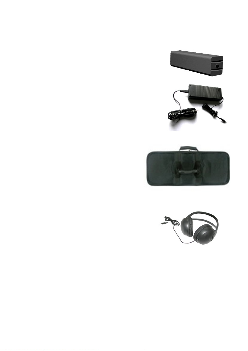
3. Batteries:
11.1 V, 2 Ampere Lithium Ion rechargeable batteries.
Battery Life: 4-6 hours
4. Battery Charger:
It is a device to charge 11.1 V 2 Ampere
Lithium Ion batteries.
Input: AC 100-240 V / 50-60 Hz / 1A (City
mains)
Output: DC 9–12 V / 400 mA
Charge duration: 10 hours
5. Carrying Case:
It is a case used for transport and
storing of the System Unit, the
210x315 Detector Head and
accessories.
6. Earphone:
It is the piece that maintains vocal
communication between the detector and
the operator. Waterproof speaker on the
electronic system is turned off when using
the earphone to enable only the operator
to hear the sound of the detector.

9
JEOTECH
SYSTEM UNIT AND JOYSTICK
10
SYSTEM UNIT AND BUTTONS
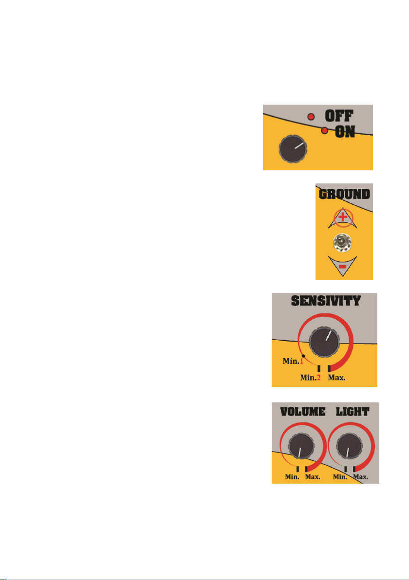
1- COMMUTATOR: The commutator
that is used for turning on the device.
2- GROUND SWITCH: The switch that is used for ground
setting.
3- SENSITIVITY : The switch that is used for
adjusting the sensivity level.
4- SOUND AND LIGHT ADJUSTING SWITCH
: The switch that is used for adjusting sound and
light level.

11
JOYSTICK
1 –SCAN : A key that enables analyzing a target when pressed passing
over it.
2- CAVITY and MINERAL : If there is a cavity effect on the device, the
“CAVITY and MINERAL” lights of the device will be on.
3- FERROUS LIGHT : The light shows that the target is a ferrous metal.
4 –POWER LIGHT : The light shows that the device is on.
5 –NON-FERROUS LIGHT : The light shows that the target is a non-
ferrous metal.
6- METAL and MINERAL : If there is a metal effect on the device, the
“METAL and MINERAL” lights of the device will be on.
7- BATTERY LEVEL LIGHT : The light shows the level of battery.
8- RESET: Resets all detector settings (Default Settings) in reference to
recent settings whenever resetting is done.
1
3
2
4
5
6
7
8

12
JEOTECH
ASSEMBLY AND CHARGING THE
BATTERIES

13
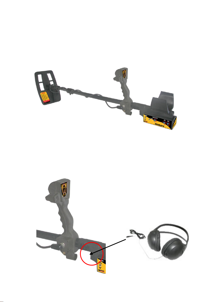
1. ASSEMBLY :
Detector head is taken off the carrying case and telescopic extension
tube is inserted, piece Nr.1 into piece Nr.2 as shown in the diagram and
tighten the sleeve.
The detector head is dismounted from the extension tube when packing
in the carrying case. Dismantling is carried out as the reverse of the
process described above.
CAUTION: Do not take apart the screws that connect the
Connecting piece and Detector Head. Take off only the telescopic
tube without damaging cable coil and suitably store in the carrying
case.
14
DETECTOR HEAD CONNECTION
Transmits the data received from detector head to the Electronic system
box. The 5 pin plugs shown in the above figure are connected to socket
on the system box.
EARPHONE CONNECTION
Enables signal sound to be switched from external loudspeaker to the
earphone. The plug shown in the above figure is connected to socket on
the system unit.
15
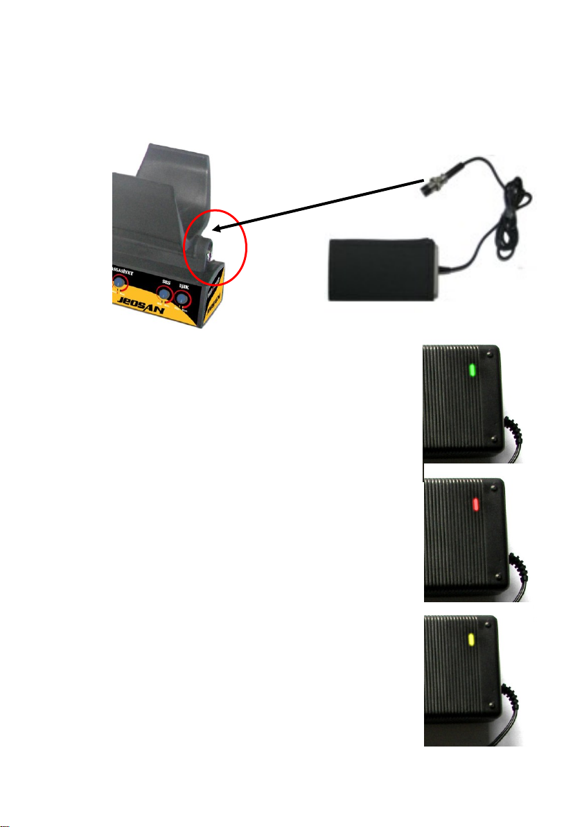
BATTERY CONNECTION
The plug shown in the above figure is connected to socket on the
system unit.
2. CHARGING THE BATTERIES:
Battery Charger State without Batteries
Installed: When the charger is connected to
the mains plug, the green light on the
charger is lit and triggers a short alarm tone.
Detection of a defective Battery: When a
defective battery is connected to the charger
green light on the charger blinks 5 times, a
short beep tone is heard and the green light
turns into red, blinks repeatedly and frequent
beeps are heard. In such a case do not use
the battery and contact the manufacturer.
Detection of a fully charged battery:
When the battery is connected to the
charger green light on the charger blinks 5
times and short beeps are heard, the green
light turns into yellow, blinks repeatedly and
infrequent beeps are heard. This indicates
that the battery is full.

16
Detection and Charging of a Depleted
Battery: When a depleted battery is
connected to the charger green light on the
charger blinks 5 times, 10 short beeps are
heard and the green light turns into blue that
blinks for a short period. During this period
the charger sets the battery charging
current. When the setup is completed a
short beep sound is heard and charging
starts.
ATTENTION: During the setting period do not disconnect the
battery from the charger.
During the charging process the blinking sequence of the blue
light decreases to 3 seconds, the battery is charged during this
period and ready for use. When the battery is fully charged a
short beep is heard and the blue light turns into yellow.
The charging period required for a fully depleted battery to
be fully charged is 10 hours.

17

18
JEOTECH
USING PHASES

19
Turning On the Device:
The ""ON/OFF" button on the device is
activated in order to turn on the device.
Checking Battery Status:
Check the battery charge indicator in the middle of the device. If three
lights are on, the battery is full. If two lights are on, the battery is half full
and if there is only one light on, the battery is about to be dead. If three
lights are on and off periodically, the device power is not enough to
operate the device. If there is no light on, the battery is flat. When the
battery charge is weak, the device settings change, which may cause
some errors. Therefore, pay attention to keeping the battery full.
Especially, take care not to use the device and charge the battery when
only one light is on. If the battery is flat or is not powerful enough, turn off
the device and connect the charger to the battery to charge it.
FULL
HALF
LOW
EMPTY

20
Use of the Light Button:
The "LIGHT" button is used to set the light
level of the device. The device is designed
as appropriate for use during day and
night. By this button, the light may be
turned on to the brightest level and it may
be ensured that the light is seen even
under the sun. At the same time, the light
may be turned off to the full extent when
one does not want to see the light. For
light settings, the light button is set to a preference between levels "Min"
and "Max" after the device is turned on and the light level is set.
NOTE: When battery is flat, all three “BATTERY” lights flash and a
sound alarm is generated.
NOTE: When search cap breaks down or when the search cap is not
detected, “VALUABLE” and “INVALUABLE” lights will flash to warn
the operator.
Use of Sound Button:
The "SOUND" button is used in order to
set the sound level of the device. In order
to be able to make the sound setting, the
light level is set by making a preference
between the levels “Min” and “Max” after
the device is turned on. When the device
is connected an earphone, the speaker
will be deactivated and the sound will
inform the operator through earphone.
Table of contents
Other Makro Detektor Metal Detector manuals


