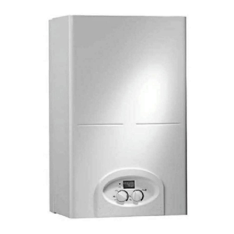
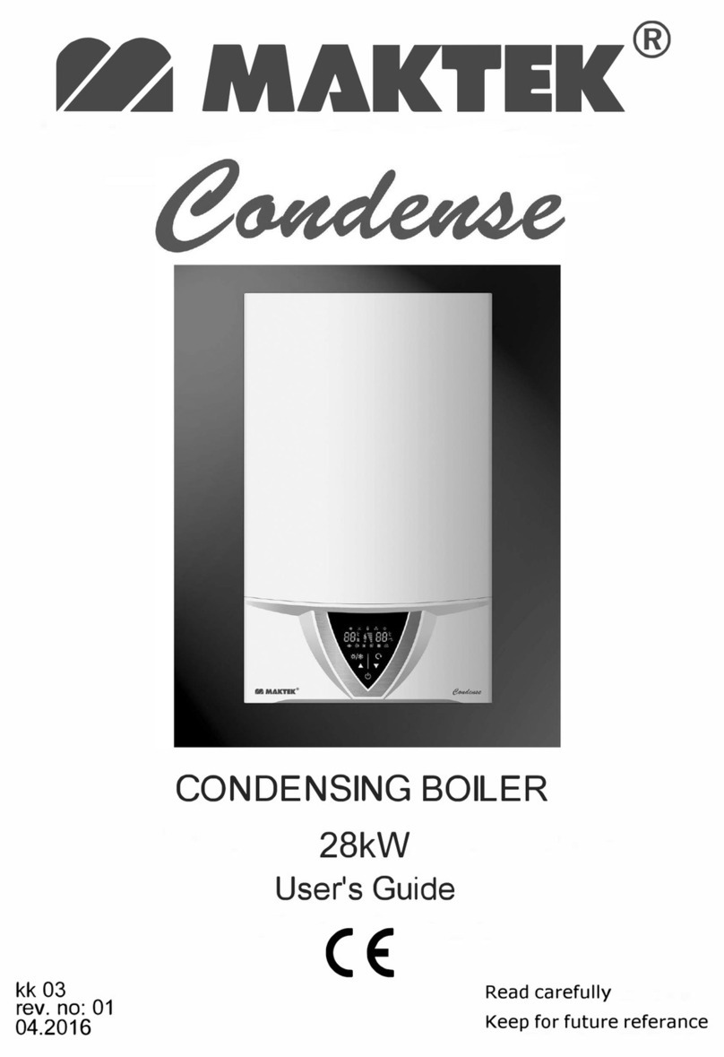
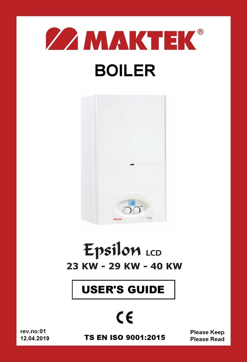
Maktek Epsilon ECO 24 User manual

®
CONDENSING BOILER
TS EN ISO 9001:2015 Please Keep
Please Read
rev.no:01
30.05.2019
USER'S GUIDE
Epsilon ECO
24 kW - 30 kW

2
2
3
4
5
5
6
7
9
9
9
10
10
10
11
12
13
13
15
15
15
16
17
18
20
21
22
22
22
23
23
23
24
25
26
27
28
1. SAFETY WARNING
1.1 SYMBOL KEY
1.2 GENERAL WARNINGS
1.3 GENERAL EXPLANATIONS
2. INTRODUCTION OF THE DEVICE
2.1 APPERANCE AND EXTERNAL DIMENSIONS
2.2 INTERNAL STRUCTURE AND COMPONENT LIST
2.3 CONTROL PANEL
3. INSTALLATION DATA
3.1 ELECTRICITY CONNECTION
3.2 OPENING THE BOX
3.3 WALL MOUNTING
3.4 POINTS TO BE CONSIDERED AT INSTALLATION
3.5 SPACES TO BE LEFT DURING INSTALLATION
3.6 CONNECTION OF CONDENSATE WATER DISCHARGE
3.7 INSTALLATION CONNECTION DIAGRAM
3.8 INSTALLATION CONNECTIONS
3.9 CHIMNEY CONNECTION
4. FLUSHING TO THE SYSTEM AND MONITORING WATER PRESSURE
5. START-UP
5.1 PRE- CONTROLS BEFORE START-UP
5.2 START-UP OPERATION
5.3 PRESSURE CURVE of THE CIRCULATION PUMP
6. USING OF THE BOILER
7. TECHNICAL SPECIFICATIONS
8. ELECTRICITY CONNECTION SCHEMA
9. SAFETY SYSTEMS AND TROUBLE SHOOTING
9.1 NO BURNING, MISLEADING FLAME
9.2 LOW – HIGH WATER PRESSURE
9.3 OVERHEAT LIMIT TERMOSTAT
9.4 ANTI CALCER SYSTEM
10. GAS PRESSURE SETTING
11. CLEANING AND MAINTENANCE
12. GUARANTEE CONDITIONS
13. IMPORTANT INFORMATIONS FOR YOUR SAFETY
14. EFFICIENT USE OF BIOLERS IN TERMS OF ENERGY CONSUMPTION
15. POINTS TO BE CONSIDERED WHILE MOVING AND TRANSPORTING
16. USAGE WITH LPG 28
CONTENT Page

1
Dear Valued Maktek Customer,
By choosing Maktek Epsilon Eco, we are honored to announce that you
have carried the harmony of the latest technology and the modern design
to your homes.
We advise you to read this guide carefully. This guide is an important
source for both installation and utilization. Moreover, since it contains
practical and technical information, you can easily benefit from it.
Maktek Epsilon Eco Boiler provides you safe and comfortable life with
conscious utilization.
Please keep this manual for using when needed.
We are stronger with you...
ATTENTION; THESE DEVICES CAN OPERATE WITH NATURAL GAS,
LPG OR WITH PROPAN. Contact with Maktek Authorized Service to
change the type of gas which is specified on the package.
The operations which are performed by unqualified services or people
invalidate the product’s warranty.
ATTENTION; gas transformation should be performed by the authorized
service according to the criteria in the attached table.

2
1.SAFETY WARNING
1.1 Symbol Key
This symbol expresses the risk of personal injury unless taking care of
warnings.
This symbol expresses the conditions can cause harms on
environment, animals or goods unless taking care of warnings.
Do not open the protective cover of the device.
Electric shock as a result of the contact with electrical items.
Personal injury like burnt as a result of contact with overheated surfaces
or cut as a result of contact with sharp surface.
Do not remove the device from the place of mounting, do not
disconnect (Get in contact with authorized service)
Flood as a result of demounted water installation.
Explosion, fire or poisoning danger as a result of demounted gas
installation. Protect the energy cable against damages.
Electric shock danger as a result of contact with not izolated open wires.
Do not leave tools or staff on the device.
Injury resulted from falling objects from device becuse of vibration.
Harms on things or animals resulted from falling objects from device
because of vibration.
Do not climb on device.
Personal injury as a result of fall down with device or fall down of device
itself. Damage risk on staff under device as a result of fall down
from the place installed.
Do not stamp on chair, stool, ladder or other things which are not
strong enough.
Personal injury resulted from falling down from heigh or cuts can be
resulted from a rapid closing of ladder.
Do not clean the device unless switching it to off position or
disconnecting energy link.
Use the device for only heating the house and getting hot
water.Damage risk resulted from inappropriate using and overloading.
Damage risk of the place resulted from inappropriate using.
Do not allow children or people who can not use the device, to
intervene in device.
Damage to device risk resulted from wrong use.

3
•Follow the instructions in this manual while using the device.
Manufacturer can not be held responsible from breakdowns and
damages from wrong use.
•Start-up, maintenance and repairs can be done by only MAKTEK
AUTHORISED SERVICES. Otherwise device will go out of
gurantee and manufacturer will not be responsible for breakdowns
or damages.
•It is dangerous and forbidden to use flammable/combustible
materials at the site of the boiler.
•Thinner, benzine etc. flammable materials must be kept away from
the place that boiler runs.
•Device must be mounted to a suitable location at a distance of at
least 2.5 meters from each side of easily flammable household
goods and flammable materials.
•Minimum ambient temperature must be 5°C when the boiler
installed in a partly covered place like balcony.When the ambient
temperature is lower, boiler must be isolated within a proper
keeping stuff.
•Only authorised service can intervene the all parts and sections
that (when) leakage is observed.
Disconnect the main energy connection, shut down the main gas
valve, open all the windows, move away the place and call for
help in case of burning smell or smoke from device.
Personal injury from burnts, breathing smoke or poisoning.
Shut down the main gas valve, open all windows, avoid from
sparkling and move away call for help if there is a gas smell in
place.
Explosion, fire or poisioning danger.
Pay attention not harming the electric cables and pipes inside
wall while making holes on wall for metal hangers.
Electric shock as a result of the contact with electrical items.
Explosion and fire danger results from gas pipe puncure.
Flood risk results from water pipe puncture.
Suitable profiled cables must be used in all electric connections.
Fire risk results from overheated law profiled cables
1.2 GENERAL WARNINGS

4
1.3 GENERAL EXPLANATIONS
Epsilon Eco Condensing Boiler provides the heating by central boiler
heating system and radiators connected to the sytem, and provides hot
water by heat exchanger.
Installation and services must be in accordance with recent standarts,
directives and instructions which will be explained in this manual.
Producer cannot be held liable for damages caused from wrong
installation and usage.
ATTENTION; Installation, start-up and maintenance must be done by
Maktek staff or staff authorized by Maktek.
ATTENTION; In case of a leakage, firstly close the gas inlet valve and
ventilate the environment, then call authorised service immediately.
WARNING !
This instruction manual is extremely important and must be kept as a
reference guide.
Follow the instructions on manual to run the boiler. Manufacturer is not
responsible for the failures and damages resulted from improper use.
Optimum lifetime of the boiler is 15 years. It should be replaced with a
new one at the end of this period.
The boiler is under warranty of the manufacturer if the product complies
with conditions specified in the warranty.
It is recommended to making annual periodic maintenance in accordance
with data on maintenance chapter. Only Maktek authorised services can
intervene the boiler.

5
2. INTRODUCTION OF THE DEVICE
2.1 APPEARANCE AND EXTERNAL DIMENSIONS

6
2.2 INTERNAL STRUCTURE AND COMPONENT LIST
1. Prosestat
2. Fan
3. Burning Room Isolation and Side Cap
4. Bimetal Limit Thermostat
5. Ionisation Electrode
6. 3 Way Motor Valve
7. Gas Valve Modulation Bobin
8. Heat Sensor Of The System
9. Hot Water Circuit Temperature Sensor
10. Pressure Gauge (Transducer)
11. Plate Exchanger
12. Gas Valve
13. Filling Valve
14. Water Flow Sensor
15. Condensing Water Reservoir
16. Circulation Pump
17. Ignition Electrode
18. Burner
19. Combustion Chamber
20. Heating Circuit Exchanger
21. Top Smoke Chest
22. Rekuperator (Condensing
Exchanger)
23. Fresh Air Entrance Flange
24. Chimney Outlet
25. Chimney Limit Thermostat
26. Expansion Tank
27. 3 Bar Safety Ventile
28. Panel Bottom Support Sheet

7
2.3 CONTROL PANEL
All functions required to run the boiler is done via two buttons on the
control panel. These functions are seen on the LCD sreen. All failure
reports are seen on screen via specific codes.
A. P1 KEY
DHW Adjustment: Temprature of the DHW is adjusted.
Desired temperature flashes on the screen.
DHW function is OFF.
Note: The boiler does not produce DHW.
TEST: Mode of adjustment by AUTHORISED SERVICE.
B. P2 KEY
OFF - RESET: The boiler is functionally switched off. In case of failure it
is used as a reset. Safety against frost and congestion are enabled.
Winter Mode: Both DHW and heating function is on. Heating
system adjustments are done. Desired temprature flashes on
the screen. DHW is priority.
Summer Mode: Only DHW function is on.

8
C. LCD SCREEN:
It shows running and failure conditions with the warning codes on screen.
These codes are:
S1 : °C (temperature) symbol.
S2 : (KS) DHW is heating.
S3 : (MS) Central System is heating
S4 : Bar (water pressure ) symbol.
S5 : Manual reset is required.
S6 : Burning initiated, boiler is running.
S7 : No burning
WARNING CODE EXPLANATION SOLUTION
E04 Low or high water pressure (page 22)
E01 No Flame (page 22)
E02 Limit thermostat (page 22)
E03 Chimney Thermostat Call authorised service.
E37 Circulation Failure Call authorised service.
E05 Heating system sensor error (page 23)
E06/E12 DHW sensor error (page 23)
E035 Misleading Flame Call authorised service.

9
3. INSTALLATION DATA
3.1 ELECTRICITY CONNECTION
•The boiler works with 230 v. 50 Hz. alternative current.
•Please make sure that the fuse supplied along with the boiler is
installed maximum 10 cm. away from the boiler.
•An electricity cable of 3x1,5 mm² must be laid out by an authorised
electrician.
•The boiler works with ground line. Both for your and the boiler's safety,
please make sure that the grounding is done properly.
•Please make the phase, neutral and ground line connection as shown
on the schema.
3.2 OPENING THE BOX
1. Put the box on the floor as arrows showing down and open the box by
cutting packing belts.
2. Open the covers by folding on 4 sides as shown in figure.
3. Turn down the box as shown in figure and pull box to up and remove it from
the box.
IMPORTANT
•The boiler does not operate when the connection is done
improperly.
•The cable of the boiler must be connected as shown:
Brown: Connect this to phase cable.
Blue: Connect this to neutral cable.
Yellow-Green: Connect this to ground cable.
Boiler
System

10
3.3 WALL MOUNTING
The installation of the gas boiler must be done by authorized dealers.
Start-up operation must be done by MAKTEK AUTHORISED SERVICE.
Your device will become out of guarantee if the installation and operation
terms indicated on this manual are not applied.
3.4 POINTS TO BE CONSIDERED AT INSTALLATION
•Pipings must be cleaned before the installation of the device.
•The gas connection of the unit must be done properly and controlled for
any leakages.
•Condensing boilers run on closed burning chamber principle. They
supply the air from outside for burning, and then exhausts the burned
gases to the environment. For this reason, the exhaust gas outlet pipe
must be installed in contact with the outside atmosphere.
•Exhaust gas pipes must not be put in closed areas where there is no air
circulation.
•Wall mounted boilers must be installed vertically on a strong wall that
can carry it.
•The unit must not be installed in connection with dirty and oily flue
where the kitchen appliances are connected to.
•Specific spaces must be left around the unit for the authorized service to
intervene in the event of a technical breakdown or maintenance. You
can find the minimum spaces required for installation indicated below.
•Installation accesories provided along with the boiler (wall plug, screw
and hooks) must be used during the installation.
•The proper installation checked by a water gauge is necessary for the
healthy operation of the boiler.
•The condensate drain hose of the appliance must be connected to a
suitable water drain as specified in this manual. (see page 11)
3.5 SPACES TO BE LEFT DURING INSTALLATION
Following ranges must be left along with installation in order to reach
internal parts of the device during maintenance and possible malfunctions.)

11
3.6 CONNECTION OF CONDENSATE WATER DISCHARGE
The condensate discharge water hose from the boiler must be connected
to a suitable acid-resistant pipe (plastic) at an angle of 2.5° towards the
floor. The pipe must be at least in 22 mm diameter and connected to a
suitable drain. The connection can be made in the following ways:
i) Connection can be done to a sink water drain inside the house. At least
75 mm siphon connection should be made when connecting.
ii) Connection can be done to a water drain outside the house.
The condensation water discharge connection should be made according
to the following figures.
Isolate pipes inside
of the building for
sealing
External pipe length maximum 3 meters
Open mouth of the pipe is connected
to the drain
Above water level, below ground
level
Ø 22 mm min.
Ø 22 mm min.
Open side of the pipe is
connected to the drain
Above water level, below
ground level
No length limit
Min 75 mm siphon
Sink

12
For such connections, the valid standards in that country must be complied
and the local public and health authorities' regulations, if any, must also be
observed. Condensation outlet pipe should be placed very carefully.
The pipe should not break when placed.
Pipe should not take the shape of a goose neck.
It should be clean.
Use the pipes in accordance with the applicable rules for the discharge of
condensate water.
Since the condensation water pH is close to 2 (acidity), necessary
precautions should be taken before any work is carried out. (Protective
gloves)
3.7 INSTALLATION CONNECTION DIAGRAM
Condensation
Water Outlet
Gas Connection 3/4”
DHW
Outlet
1/2”
Heating Water Outlet 3/4”
Filling Valve
Cold Water Inlet 1/2”
Return Water Inlet 3/4”
Condensation Tank
Cleaning Cover
Condensation Water
Outlet

13
3.8 INSTALLATION CONNECTIONS
•At DHW function, please make sure that the pressure of the city water
network on cold water inlet side is not more than 6 Bars. If the network
pressure is more than 6 Bars, a pressure regulator must be added. In
order to run DHW system, minimum pressure level of the network must be
0.8 Bar.
•In order to provide a good circulation in heating function, installation pipes
must be selected accordingly and diameter structure must not be allowed
at elbow passage. In selection of the pipe diameters, pipe resistances
above the pump capacity should be avoided by using the pump pressure
curve.
•When there is an excessive pressure increase at heating system, the
security ventile operates in order to discharge the excessive water.
•When radiator thermostatic valves are installed in the heating system and
when the heat balance is provided at all isolated sections, if the
thermostatic valves turn off the system: Automatic by-pass system
immediately runs in order to provide the minimum circulation in heat
exchanger .
•Gas installation connection must be done by gas tightness pastes. Never
use linen or teflon. The gas inlet pressure mentioned in this manual must
be strictly obeyed.
3.9 CHIMNEY CONNECTION
Mounting of condensing chimney kit must be in accordance with mounting
schema which is given with boiler.
1.Elbow Set
2.Extra Pipe Joint
3.Clips 37mm
4.Condensing Chimney
5.Elastic Wall Badge
82
82

14
ATTENTION: Chimney must be installed upward with a slope of 3% angle
in order to provide the leaking of condensing water flow into the condensing
tank in the boiler.
Chimney should not come into contact with flammable materials and get
through flammable wall material.
Part of the chimney which stays inside the wall, must be maximum 60 cm in
behind connections and must be maximum 40 cm in sidelong connections.
Allowed maximum chimney length is 4 m. If otherwise, please consult the
manufacturer for technical information.
Important: There is an air protestat inside the boiler to shutdown the boiler
in case of a possible failure inside of the chimney. In this case, please
contact your local service.
Maximum length 4 meter
Minimum length 0.5 meter
Standart connection
min slope 3°
chimney kit extension
min slope 3°
slope
Clamp
118 mm
150 mm
118
150 mm
ascending
slope
180 mm
150 mm
52 mm
3°
4000 mm
max

15
4. FLUSHING TO THE SYSTEM AND MONITORING WATER PRESSURE
Water pressure of the heating system is digitally displayed on LCD screen.
To display the pressure, turn P1 Knob to TEST position, and move P2 to
SUMMER position on the control panel (page 7). Water pressure will be
displayed as bar (unit of pressure).Air must be purged from radiators in the
initial flushing process. Please follow these steps to start initial flushing:
1- Open all purgers in central boiler installation and radiators.
Attention: Rotate directions of water evacuation holes and place a pot under
each purger in order to prevent environment from water damages.
2- Open the filling valve (page 12) which is placed underneath the boiler
and start filling water into the system.
3- Close all the purgers when blister-free water starts to come from purgers.
4- Continue to flush until the system pressure comes up to 1,5 Bar, then turn
off the filling valve.
Attention: It is recommended to make initial flushing with at least 2
people.While one person is controlling the radiators and closing the purgers,
the other one can control the pressure by standing over the boiler and close
the filling valve if needed.
In case of water shortage in closed circuit system after running of the boiler, it
is necessary to add water to system by opening filling valve. Radiators must
be checked if there is air in them or not.
5. START-UP
Boiler must be put into service by only Tecnical Services in order to run the
boiler efficient and safe, also for the validation of guarantee conditions.
5.1 PRE- CONTROLS BEFORE START-UP
1.The gas type and its pressure must be controlled.
2.Automatic purger fuse on the circulation pump must be loosened.
3.The pressure inside the system must be controlled from the manometer.
The pressure must be around 1,5 Bar.
4.In order to dispose the air from all of the system , take out the screw in front
of the pump. By this way, whether the pump mill is congested or not can be
controlled and any air that is congested can be discharged.
5.Dispose the air from the purgers on radiators.
6.Discharge the air in the hot water system by turning on hot water tap.
7.Check the installation of hermetic flue kit.
8.Check whether all valves in the system are turned on.
9.Check that the accuracy of condensate drain connection.

16
5.2 START-UP OPERATION
Start-up must be done by the Maktek Authorised Services to validate the
warranty conditions.
The below must be applied:
ATTENTION; The condensation reservoir of the boiler must be filled with
water during the first start-up. To ensure this, add 1/4 lt of water from the
boiler flue outlet as shown in the figure below before first operating.
ATTENTION; If there is not enough water in the condensation reservoir
of the boiler, device can run by emiting smoke for a while.
-Make sure that fuse switch, which enables the energy connection of
boiler, is open. If the boiler has waited for a long time after the installation
in OFF mode without start-up, authorised service must check the
circulation pump in case of any squeezing.
• Turn on all the valves on boiler and installation pipes.
• Closed circuit water pressure must be at 1,5 bar (page 15).
• Choose the position of use with the help of P1 and P2 buttons on control
panel (page 7 and 18).
• You can start using the boiler by setting temperature at desired level.

17
5.3 PRESSURE CURVE of THE CIRCULATION PUMP
3 speed circulation pump is used in MAKTEK Epsilon Eco Boiler. It is
possible to set the circulation with these three speeds according to resistance
required by installation.
EPSİLON ECO 24-30 kW

18
6. USING OF THE BOILER
P1 KEY SETTING MODES P2 KEY SETTING MODES
SUMMER MODE:
When Summer mode is chosen, boiler runs only to
get DHW (30-60°C) set by P1 key when there is
DHW demand.
Opening of the hot water tap is automatically
perceived and boiler generates the hot water
needed. Provides constant temperature comfort
with full modulation system.
In stand by mode when hot water is not demanded,
pressure value of the water inside boiler is
displayed on the screen.
OFF/RESET MODE:
In Off mode, boiler is shut down.
In OFF mode, automatic protective functions below
are in use:
•DHW Freezing Protection
•Central System Freezing Protection
•Pump Squeezing Protection
•3 Way Valve Squeezing Protection
When manually reset error occures, key should be
placed to RESET position and then should be placed
to previous position (before reset position). This
process resets your device. In this condition “OFF” is
displayed on LCD screen.
ATTENTION!: Electricity, gas and water connections should not be
disconnected in order to run the freezing protection function and other automatic
protection fuctions.
DHW
OPEN
DHW
CLOSED
TEST
CENTRAL SYSTEM
TEMPERATURE
SETTING
WINTER
SUMMER
OFF/RESET
CENTRAL
SYSTEM
TEMPERATURE
SETTING
This manual suits for next models
1
Table of contents
Other Maktek Boiler manuals
Popular Boiler manuals by other brands

UT KATILAI
UT KATILAI UT-100 User instructions
Unical
Unical KONe R 18 Installation and Servicing Manual
Rinnai
Rinnai Q175S Specifications

Viessmann
Viessmann VITORONDENS 200-T Service instructions

Buderus
Buderus Logano G225 Installation and service instructions

SANT ANDREA
SANT ANDREA MIRAGE E GAZ - SCHEMA manual
