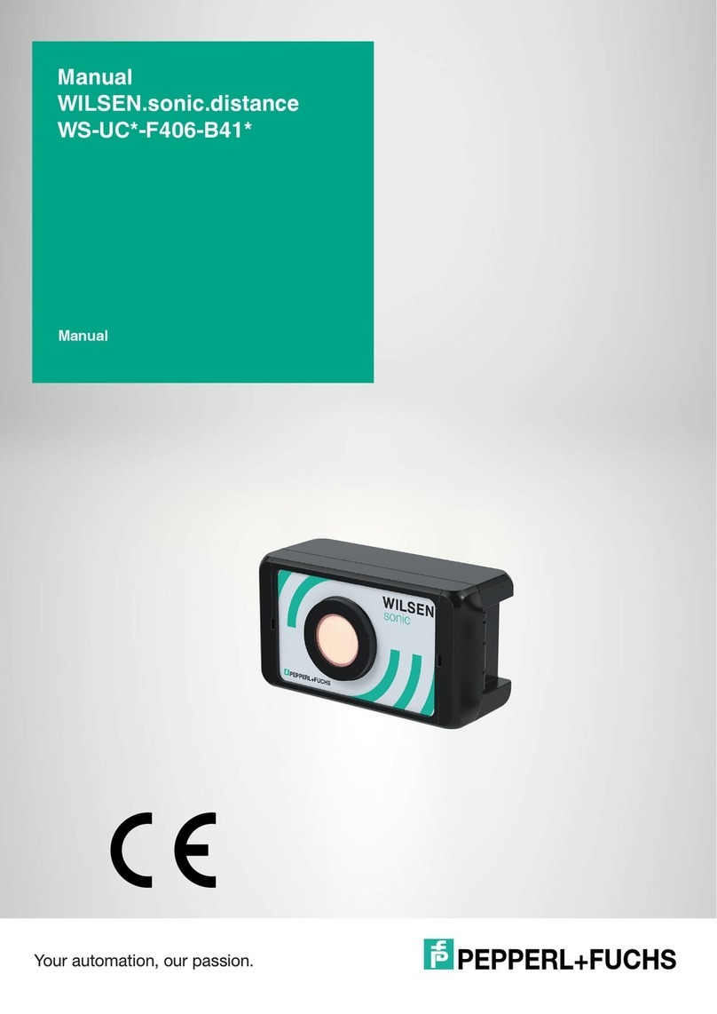
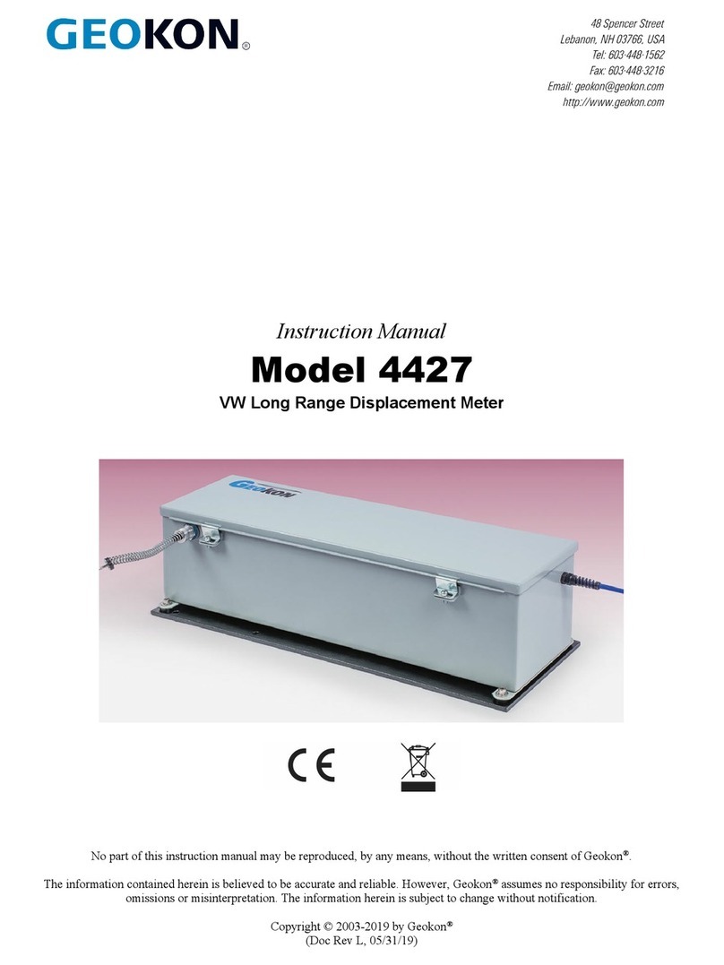
Malema M-1500 Series User manual

malema flow sensorsmalema flow sensors
malema flow sensorsmalema flow sensors
malema flow sensors 11
11
1
Inline Ultrasonic Flowmeter
Ultrasonic Flowmeters
Installation and Operating ManualInstallation and Operating Manual
Installation and Operating ManualInstallation and Operating Manual
Installation and Operating Manual
M-1500 SeriesM-1500 Series
M-1500 SeriesM-1500 Series
M-1500 Series
• Ultrasonicflowsensingtechnology-robust
proventechnology
• Capableofmeasuringflowsfrom
1 - 4000 ml/min
• Measuringaccuracyof±2% ofREADING
(5%of readingbelow 20%of flowrange)
• Compactdesign -ideal foruse insemi-
conductorprocess tools
• Sensors/Transducerssitoutsidetube-hence
completelynon-invasive
• No pressure drop - since there is no
obstructioninflowpath
• Minimalbubble entrapment compared to
other designs due to INLINE flow path
• Idealforprecisemeasurementsinlow flow
applications
• No moving parts: hence no particle
generation
• Fastresponse time(0.1 sec)ideal forCMP
process measurements where flow
fluctuationsarehighduetouseofperistaltic
pumps
• Transducers resistant to harsh chemical
environments(NEMA4Xcompliance)
• CVD, CMP, and lithography tools
• Medical Devices
• Wet process systems
• Corrosive chemical distribution
• Laser equipment
• Cooling systems
Thisflowmeteruses anon-intrusive methodto determinethe
flow rate of the liquid. Two piezoelectric transducers are
mountedontheouterdiameteroftheflowtubeandareexcited
producingavibration.Alternatelyeachtransducer’sultrasonic
disturbancetransmitsthroughthetubingwallandispropagated
along with the liquid flow and back against the flow. The
propagation wave velocity varies with flow rate and is
proportionaltoflow rate.The flowrate canbe determinedby
measuringthevariationofthesepropagationwavevelocities.
(Coveredby U.S. Patents)
ApplicationsApplications
ApplicationsApplications
Applications
FeaturesFeatures
FeaturesFeatures
Features
OperationOperation
OperationOperation
Operation
CertificationsCertifications
CertificationsCertifications
Certifications
AppliedforUL andCE certificates.
TheM-1500series isaninline primaryflow sensor and
externallymountedcontrollerunit.Theflowsensorisa
straightthroughflowtubethatuses“TransitTime”differential
methodwitha microprocessorbasedmeasurementdesign
forprecisemeasurement offlowrate. Thecontroller elec-
tronicsreceivesthe rawflow rate signalfrom thesensorand
providesflowrateinformationinterms ofanalogandpulse
outputsignals.

22
22
2Malema Flow Sensors • 1060 South Rogers Circle • Boca Raton, Florida 33487 • 1-800-637-6418
561-995-0595 • Fax (561) 995-0622 • http://www.malema.com • © Copyright 2001
Ultrasonic Flowmeters
M-1500 Series
DimensionsDimensions
DimensionsDimensions
Dimensions
SENSOR DIMENSIONSSENSOR DIMENSIONS
SENSOR DIMENSIONSSENSOR DIMENSIONS
SENSOR DIMENSIONS
DIMENSIONS FORDIMENSIONS FOR
DIMENSIONS FORDIMENSIONS FOR
DIMENSIONS FOR
SINGLE CONTROLLERSINGLE CONTROLLER
SINGLE CONTROLLERSINGLE CONTROLLER
SINGLE CONTROLLER
Figure 1
Figure 2
(Available in 1/16” & 1/4” Also)

malema flow sensorsmalema flow sensors
malema flow sensorsmalema flow sensors
malema flow sensors 33
33
3
Inline Ultrasonic Flowmeter
Ultrasonic Flowmeters
CertificationsCertifications
CertificationsCertifications
Certifications
PerformanceSpecifications
FlowRange: 1 - 4000ml/min
Accuracy: +2% ofreading
(for 20 - 100% of flow range)
+ 5% of reading for 0 - 20%
offlowrange.
Repeatability: + 0.5%
FunctionalSpecifications
AnalogOutput: Isolated4-20 mA (Maximum load
resistance of 500 ohm) current
output.
Pulse Output: Isolated Open Collector (15V, 15 mA)
Frequency of 1000 hz at flow rate
of 100%
Lowflowcut off: 2% - Enabled by DipSwitch
ElectricalInput: 24 VDC + 10%
300mA
OptionalDisplay: 4 digit7segmentdisplay,indicates
instantaneous flow rate in ml/min
AmbientTemperaturerange: 32 - 115 F (0 - 46 deg C)
Fluid Temperaturerange: 50 - 140 F (10 - 60 deg C)
MaximumOperatingPressure: 70 psigfor PFA
CableMaterial: PTFEJacketed Custom
shieldedcable.
CableLength: 3 Metersmax.
FluidViscosity: 8 cP max.1
TimeConstant: Field Adjustable(0.1s to5s)
1Higher viscosities would require special tube sizingand
customcalibration.
SensorHousing : PP or PTFE orPVDF
Non-wetted parts: Peek, PP, PVDF, VitonA, FEP
Wettedparts:PFA(high purity)
PhysicalSpecifications
Sensorunit:Equivalentto NEMA4X(IP65)
Controller: Equivalentto NEMA2 (IP20)
SensorUnit Dimensions: 1.3” (W)X 2.0”(H) X 4.4”(D)
SingleControllerDimensions :4.0”(W) X1.65”(H) X4.3” (D)
SpecificationsSpecifications
SpecificationsSpecifications
Specifications
MaterialSpecifications

44
44
4Malema Flow Sensors • 1060 South Rogers Circle • Boca Raton, Florida 33487 • 1-800-637-6418
561-995-0595 • Fax (561) 995-0622 • http://www.malema.com • © Copyright 2001
Ultrasonic Flowmeters
M-1500 Series
InstallationInstallation
InstallationInstallation
Installation
Sensor
Selectlocationformountingsensor thathas
•Ambienttemperature (0 to 60ºC (32 to 140
F)awayfromdirectsunlight.
•Freefromelectromagneticinterference. Keep
awayfromheavyelectrical devicessuchas
motors,pumps,power-relays andsolenoid
valves.
•Noair orgas bubblesin theflow,sincethey
causehindrancesto propagation ofultrasonic
waves.
•Nowater splashes or corrosivegases.
•Hasease ofaccess formaintenance.
Figure 3
MountingHardware: Usefour M4x X (X= 0.35”+ thicknessof themounting plate)Philip panhead screw
(notprovided) to secure the M-1500sensor onto the panel.
Itisadvisable tomounttheflow sensorwiththe flowgoingvertically upward. Thisensuresthat no bubblesget
trappedwithinthesensor. Thisalsopreventsanysedimentationfromthefluidfrom accumulating insidethe
sensorsection.
Itisadvisableto mountthesensorat apositioninthe flowcircuitthat hasmaximumfluidpressure (upstreamof
flowcontrolvalves). Thesensorshould alwaysbefilledwith liquid(evenwhenthereis noflow).
Incasethe flowsensor cannotbemounted vertically, itisOK tomount itinANY convenientorientation. The
flowsensorwillfunctionsatisfactorilywhenmountedinANYorientation. However,thepersoninstallingtheunit
mustensure thatno bubblesget trappedin sidethe sensortube andthe fluid doesnot havesolid particlesthat
wouldsedimentinsidethe sensortubesection.

malema flow sensorsmalema flow sensors
malema flow sensorsmalema flow sensors
malema flow sensors 55
55
5
Inline Ultrasonic Flowmeter
Ultrasonic Flowmeters
Controller
Thecontrollermodule canbepanel mountedasshown infigure4 below
CAUTION
All possible electric noise sources in the vicinity of flowmeter, such as motors, pumps, power relays or
solenoid valves, should be fitted with suitable surge suppressor.
Figure 4

66
66
6Malema Flow Sensors • 1060 South Rogers Circle • Boca Raton, Florida 33487 • 1-800-637-6418
561-995-0595 • Fax (561) 995-0622 • http://www.malema.com • © Copyright 2001
Ultrasonic Flowmeters
M-1500 Series
WiringWiring
WiringWiring
Wiring
Thesensor unit issupplied with a6 ft cable (standard). Theconnector at theend of thesensor cable needsto
beconnected tothe controller boxat the locationmarked “SENSOR”.
NOTE: Thesensor shouldbe connectedto the controllerBEFORE supplyingpower tothe unit. Failure todo
thiswillresult inmalfunctionof theunit. Incasethis sequenceisnot followed–please powertheunit down–
disconnectand reconnectthe sensorconnector andthen power theunit up.
Thefigure belowshowsthe connectorlocated onthe backof thecontroller. Thedescriptionof eachterminal is
listedonthefigure5.
Pleaseuse electrical conductorsof sizeAWG 24-20stripped and tinnedabout 5 mm.These canbe inserted
intotherespectiveterminalhole. Theterminalblock hasself-lockingmechanismthatwillbind onthestripped
electricalwire. Torelease theconductor,press the respectivetab nextto theterminal hole.
Caution: Checkvoltagesupply tobe 24VDC BEFOREconnectingto theunit. Excessive/incorrect voltage
cancausepermanent damageto theunit.
Figure 5

malema flow sensorsmalema flow sensors
malema flow sensorsmalema flow sensors
malema flow sensors 77
77
7
Inline Ultrasonic Flowmeter
Ultrasonic Flowmeters
Pre - Start-up CheckPre - Start-up Check
Pre - Start-up CheckPre - Start-up Check
Pre - Start-up Check
Confirmthefollowingbeforeturningpoweron
•Wiringcorrespondswithfigure5
•Makesurethe flowsensor andthecontroller serialnumbers match.
•Verify cableconnectionbetweensensor andcontrollerfor theultrasonicflowmeteris secure.Ensurethat
theconnectoris lockedonwith apositive“click”.
•Makesure thesensor andthe controllerare connected beforepowering theunit.
•Powersupply voltageat terminal is24 VDC +10%
•Flowdirection correspondswith arrowmark ontheflow sensor.
•Flowdetectoris completelyfilledwith liquid.Confirmno leakage,nobubblesand nodepositsare
observed.Iftherearebubbles,eliminate thembyflushing.
Zero SetZero Set
Zero SetZero Set
Zero Set
Itisalwaysadvisableto “ZeroSet”duringinitialinstallation –beforestartingANYflow measurements. Please
followthe procedurelisted below toensure that the ZERO setis done inthe propersequence.
Caution: Incorrectly “ZERO” set on the flow meter would give erroneous readings.
•Flowliquidcontinuouslyto ensureALLair bubblesarepurgedout (largeandsmall bubbles).
•Shutoffflow –ensureliquidinsidethe sensortubingisSTATIONARY.
•Verifythereadingon thecontrollerunitas“ZERO”.
•Ifyes, theultrasonic flowmeter isready touse and doesnot haveto be“ZERO SET”
•Ifnot –ensurethat thereading isSTEADY. Thisindicates thattheflowmeter needsto be“ZERO” set.
•Press“ZERO”buttononthecontrollerwhilemaintainingSTATIONARY liquidinsidethetube.You
shouldsee thereading on thecontroller goto zeroin a fewseconds
•Whiletheflowmeterisbeing“ZERO SET”,theNORMledon thecontrollerwillblink.Thisis normal
andindicatesthattheunitis doinginternalcomputing.Donot beginflowliquidunlesstheNORM led
glowssteady.
•Whenthereadingreaches zero(withstationaryfluid), thentheultrasonicflowmeter isreadyforuse.
Calibration For Different FluidsCalibration For Different Fluids
Calibration For Different FluidsCalibration For Different Fluids
Calibration For Different Fluids
Ifthereisanychangeinthe“fluidmedium” i.eanyfluidotherthanthefluidonwhichthe flowmeterhasbeen
factorycalibrated theflowmeter needsto be“CLEAR”set so asto show flowreadings.
Pleasefollow theprocedure listed belowto ensurethat the CLEARset is donein theproper sequence
•Flowliquidcontinuouslyto ensureALLair bubblesarepurgedout (largeandsmall bubbles).
•Shutoffflow –ensureliquidinsidethe sensortubingisSTATIONARY.
•Press“CLEAR”buttononthecontrollerwhilemaintainingSTATIONARYliquidinsidethetube.You
shouldseethereadingon thecontrollerdisplay.This readingwillnecessarilynot bezeroalthoughthe
fluidisstationary.
•Toensurethatthe flowmeterreadssteady“ZERO” understationaryfluidconditions pleasefollowthe
stepsmentionedunder thesection “ZeroSet”.

88
88
8Malema Flow Sensors • 1060 South Rogers Circle • Boca Raton, Florida 33487 • 1-800-637-6418
561-995-0595 • Fax (561) 995-0622 • http://www.malema.com • © Copyright 2001
Ultrasonic Flowmeters
M-1500 Series
.oN.SnonemonehPnoituloSdnaesuaCelbissoP
1wohstonseodyalpsiD gnihtyna
erusekamesaelP.ylppusrewopoN detresnieraseriwdennitehttaht riehtotnihguonepeedyletauqeda .elohlanimretevitcepser
2putiltonsidelMRONehTevobasaemaS
3noylsuounitnocsidelRRE8146-736-008-1troppuslacinhcetllaC
4"E"swohsyalpsiD
siebutrosnesehtfideyalpsidsiE deppartneeraselbbubfiroytpme refeR.ebutrosnes0051-Mehtedisni dilavtegot"teSoreZ"noitcesot rellortnocretemwolfehtnognidaer
5"rO"wohsyalpsiD
ehtedisniwolfehtfideyalpsidsi"rO" deificepsehtnahtretaergsiebutwolf tsujdA.tinuralucitraptahtfoelacslluf ehtdna,elacsllufwoleb,etarwolfeht gnidaerdilavawohsdluohsretemwolf
6"----"swohsyalpsiD
retemwolfehtfideyalpsidsi"----" gnorwehtnidetnuomsirosnes ehterusekaM.dewolfdnanoitcerid ehthtiwecnadroccanisinoitceridwolf .rosnesretemwolfehtnoworra
7elbatsnusignidaeryalpsiD snoitidnocwolfgnirud
elbatsnuemocebnacgnidaeryalpsiD tneserpselbbuborcimeraerehtfi hsulF.ebutrosnesretemwolfehtedisni orcimehtevomerotebutrosneseht wondluohsgnidaerehtdnaselbbub elbatseb
TT
TT
Trr
rr
rouble Shooting Guideouble Shooting Guide
ouble Shooting Guideouble Shooting Guide
ouble Shooting Guide

malema flow sensorsmalema flow sensors
malema flow sensorsmalema flow sensors
malema flow sensors 99
99
9
Inline Ultrasonic Flowmeter
Ultrasonic Flowmeters
Operation and FeaturesOperation and Features
Operation and FeaturesOperation and Features
Operation and Features
Theflowsensor,once set-up,willmonitor and reportliquidflows. The sectionbelowliststhe variousfunctions
thatmay beset by DIPSwitches locatedon the frontpanel ofthe flow meterCONTROLLER
gnitteShctiwSPIDnoitcnuFnoitisoPhctiwS
1"NO"teserPyrotcaFhctiwStoNoD
2"NO"teserPyrotcaFhctiwStoNoD
3)S.F%(ffotuCwolFwoL ffoffotucwoL-NO noffotucwoL-FFO
4noitceriDwolF esreveR-NO drawroF-FFO
5wolFelacSlluF egnaRwolFwoL-NO egnaRwolFhgiH-FFO
6tnatsnoCemiTtuptuOwoleBelbaTeeS
7tnatsnoCemiTtuptuOwoleBelbaTeeS
8tnatsnoCemiTtuptuOwoleBelbaTeeS
PID HCTIWS 6
PID HCTIWS 7
PID HCTIWS 8
emiTtuptuO tnatsnoC SUTATS
NONONOceS5.0
NONOFFOceS0.1
NOFFONOceS0.2 YROTCAF TES
NOFFOFFOceS5.2
FFONONOceS0.3
Time Constant Settings
TheM-1500 flowmeterhas ano movingparts andif setup correctly,should notrequire anymaintenance.
Sinceit hasno movingparts thereis no wearand tearin M-1500ultrasonic flowmeter. However,we recom-
mendthefollowingtoensuresmooth andreliableoperation
•Checkforleakage aroundpipe connections orliquid penetrationintothe flowsensor.
•Checkfor mechanicalstressto flowsensor, whichcould becaused bywrapingof connectingpipes or
looseconnectionscauseby mechanicalvibrationofpipes.
MaintenanceMaintenance
MaintenanceMaintenance
Maintenance
Table of contents
