Malema M-200 User manual

malema.com
M-200
High ow,
adjustable ow switch with right angle Flow
Operang Instrucons
and
Quick Start Guide

malema.com
Table of Contents
Introducon 03
Operaon 03
Storage and Handling 03
Installaon Instrucon 03
Construcon 03
Specicaon 04
Cercaon 05
Dimensional drawings 05
Flow Seng 07
Ordering Informaon 08
Warranty 08

malema.com
Introducon
The M-200 Series ow switches are engineered and eld tested for sensing increasing and decreasing ow rates of gases or
liquids. Pressure variaon eects are minimal. This series features such versality, economy, and accuracy that they can be used
in virtually any applicaon requiring fool-proof inexpensive ow detecon.
Operaon
The ow switch is acvated by ow forcing a piston kept in place by a spring to travel past a reed switch. This provides a posive
signal aer a certain amount of travel. Set point adjustment is controlled by adjusng the posioning of the reed switch.
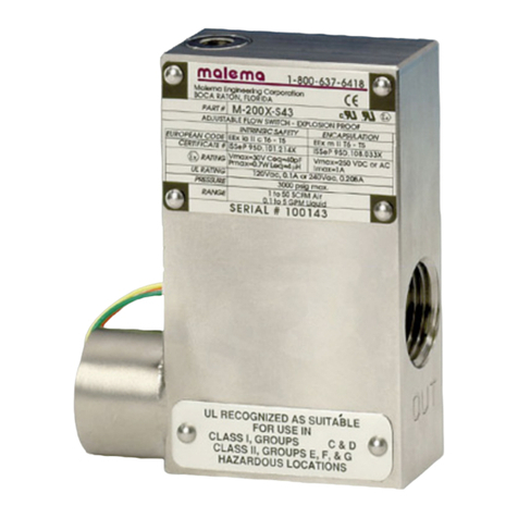
llustrated is the M-200 Model with 3/8” ports.
Storage and Handling
Storage condions
Store the product under packed condion in an an-stac bag. The storage place shall be free from moisture, mechanical shock
and vibraon. The ambient temperature shall be between 0°C and 60°C and the humidity between 5% and 80% R.H. without
condensaon.
Unpacking and Product Inspecon
On delivery, check the product for damage. Conrm that the model code on the label matches the specicaon in the purchase
order.
Installaon Instrucons
This product can be mounted in any orientaon. Adequate ltraon and sealing procedures should be used when mounng in
ow lines.
Operang Environment
Choose a locaon with an ambient temperature of 10-35°C and relave humidity value <80% RH without exposure to direct
sunlight. Avoid environments with high electromagnec noise or vibraon. Make sure that the module is protected from cor-
rosive liquid or water splashes. For best performance avoid corrosive environments since they may degrade the performance of
the electronics aer a period of me. Easy access for maintenance and inspecon is always recommended.
Construcon
The M-200 Series comprises a Body, piston, and Retaining rings. Selecng a ow switch begins with selecng the body; this
series is available in 316 Stainless Steel. The M-200 series contains one moving part (i.e. the piston) and two retaining rings that
are in the uid path. Construcon of the piston is important from a design perspecve. We manufacture three types of pistons
(It is crical to select the correct piston for your applicaon): 316 Stainless Steel, PTFE encapsulated, and Special All-Metal Pis-
ton.
1. The standard piston is a 316 Stainless Steel piston with epoxy to hold the magnet in place. This piston is recommended for
non-aggressive uids and inert gases. Stainless Steel retaining rings are typically used with this piston type.
03

malema.com
2. The second piston that is available is a PTFE Encapsulated one. The piston is a magnet that has PTFE moulded around it and
then machined to the appropriate conguraon. These pistons are primarily used in PTFE ow switches and also in other ow
switch bodies ( typically 316SS and Acrylic bodies ) where customer prefer a piston that does not have epoxy in the uid path;
as well as a piston that is impervious to aggressive uids and gases. This piston is highly recommended for medical applicaons.
Hysteresis on these pistons does tend to be slightly higher (10 to 15% ) than metal piston due to friconal eects, weight,
and surface adhesion consideraons. Prior to selecng this piston, uid temperatures, and uid compability with PTFE must
be taken into account because certain aggressive chemicals at specic temperatures tend to swell PTFE causing the piston to
change shape resulng in failure of the product. Stainless or PTFE retaining rings can be used with this piston.
3. The third piston that is available is a Special All-Metal piston with no epoxy ( only available in 316SS ). This piston is fabricated
in a proprietary process with only one weld seam ( leak tested ) which presents an all 316SS surface to the uid path.
This piston is recommended for those applicaons where the piston could experience a lot of cycling wear. This piston has
been tested to 250,000 cycles at 125 psi. Stainless Steel retaining rings are recommended for this piston type for low pressure
applicaons and an orice disc ( See Universal Mounng Diagram ) is recommended for high pressure ( 125 psi ) applicaons.
SPST vs SPDT
The standard unit is provided with a SPST N.O. (N.O = Normally open at rest) dry reed switch. Increasing ow past point will close
(acvate) the switch. Decrease ow will open (de-acvate) the switch).
SPST NC. (N.C = Normally close at rest) models are closed at rest. Increasing ow pass set point opens the switch and decreasing
ow to set point will close the switch( Typically used to detect loss of ow condion in overall systems)
SPDT (Single Pole Double Throw) switches have both N.O. & N.C. conguraons by using a common pole along with two addi-
onal poles to achieve this dual capability.
Conversion from N.O. (Normally Open) to N.C. (Normally closed)
1. Loosen allen set screws (4 - 40) on face of body. These are the set screws holding the reed switch in place.
2. Move the reed switch downwards unl it shows a closed contact on the mul-meter.
3. Tighten (4 - 40) allen set screws on face of the body.
4. Cycle unl on and o by turning upside down to simulate ow. This may necessitate some renement of the exact locaon
of the reed switch as determined in step 2.
Precauons during installaon
1. Avoid any foreign parcles during installaon.
2. Large metallic and/or magnec elds may aect the principle of operaon of these units. if disturbance is detected,
magnec shielding may be necessary to ensure correct operaon of the ow switch.
3. During installaon of explosion proof versions carefully screw in the conduit connector for the electrical leads piping so
as to avoid damaging the reed switch leads or reed switch capsule which may lead to shorng the switch installaon. 6 (Six
threads) have been provided for installaon.
4. Electrical rangs etc. have been discussed later in this bullen. it is advisable to keep within those rangs as excessive
power will FRY the switch.
Electrical Protecon/Rangs
The electrical Reed Switch is rated for several million cycles and should rarely require replacement. Most switch failures are
the result of overloading. DO NOT EXCEED RATED CAPACITY, as this will cook the REED SWITCH, Catalogue rangs are based
upon D.C. resisve loads, however A.C. loads are also commonly switched.
Inducve load switching- Unless appropriate contact protecon is provided with either a diode or R.C. network, inducve load
switching will cause the contacts to sck.
Capacive load switching - The stac capacitance in cables may cause permanent or intermier contact scking. Contacts may
be protected by a series surge protector of 0.5 to 5 mAH, depending on the load. in some instances, a 10-500 ohm resistor can
replace the surge suppressor.
Cleaning
Cleaning the ow switch is easily accomplished without removing from the line. By unscrewing the clean out plug, the mag-
nec piston may be removed and the ow passage ushed or cleaned. Care should be taken to thoroughly clean the piston
before replacing ( replace the piston as shown in see page 3 gure 2. if the piston is replaced incorrectly, incorrect operaon
will result).
1. A magnet may be used to remove the magnec piston.
2. PTFE end plugs (on PTFE models) should not be over ghtened.

malema.com
Specicaons
04
Construcon Materials
Reed Switch Replacement
For reed Switch replacement
1. Loosen allen set screws (4-40) on face of body.
2. Remove and replace reed switch if needed.
3. Normally Open
Move switch downward unl switch closes then move upward unl switch opens. Very gently reghten allen screws.
Normally Closed
Move switch downward unl it closes then move upward very slightly maintaining a closed contact. Very gently reghten
allen screws.
4. If possible cycle unit on and o to test. if unit is not installed, turning upside down will simulate the ow.
Housing Acrylic Aluminium Brass 316SS PTFE
Piston 316SS PTFE
Orice Plate or disc 316SS PTFE
Spring 316SS N/A
Retaining Ring Stainless Steel (PH 15-7 MO, AMS 5520, AISI-632)
(Passivated) PTFE
Pressure and Temperature
Specicaons
Maximum Operang (psig)
Burst (psig)
Maximum Operang Temperature
200
400
77°C (170°F)
1,000
3,000
149°C (300°F)
1,500
3,000
149 C (300oF)
3,000
5,000
149 C
(300oF)
80
160
104 C (220oF)
Flow calibraon
Set point Accuracy
Set point Dierenal( Deadband )
Repeatability
( Higher accuracy units available )
10% maximum
15%
± 2 maximum
Reed Switch Data
(Electrical Rangs)
Reed Switch
Switching Voltage
Breakdown Voltage
DC Resisve
AC Resisve
Switching Current
10 Was SPST or 3 Was SPDT (Hermecally Sealed)
UL Recognized. File E47258
Operang temperature -40°C to 125°C
200 VDC ( 170 VDC for SPDT )
250 VDC ( 200 VDC for SPDT )
10 VA (3 VA for SPDT )
10 Was (3 Was for SPDT )
0.5 A ( 0.25 A for SPDT )
1.2 A ( 0.5 A for SPDT )
Lead Wires No 24 to 18 AWG. 18” length, Polymeric UL Recognized
( Belden cable or special shielded cable is available )
Lead Wires Color
SPST: 2 blue wires
SPDT: Green - Common, Yellow - Normally Closed,
Orange - Normally Open

malema.com
UL Recognised
UL Recognised for Non Hazardous locaon – UL 138467
CE Compliance
Malema ow switches meets CE compliance under LVD 2014/35/EU. RoHS and REACH can be obtained from
Malema on request.
Cercaons
Dimensional and Cut-Away drawings
Illustrated is the M-200 model with 3/8” ports
Housing A B
Acrylic 1.25” 0.625”
Aluminum 1” 0.500”
Brass 1” 0.500”
316SS 1” 0.500”
PTFE 1.25” 0.625”
05
CONTACT ARRANGEMENT
Electrical Color Coding
SPST 2 Blue Wires
SPDT
Orange -Normally Open
Yellow - Normally Closed
Green - Common

malema.com
Dimensional and Cut-Away drawings
Illustrated is the M-200 model with 3/4” ports
Illustrated is the M-200 Model with SAE8 ports.
* Note: The M-200 Model with 3/4” ports is only available in Brass, PTFE and 316SS
06
* Note: The M-200 Model with SAE8 ports is only available in Brass and 316 Stainless Steel

malema.com
FLOW SETTING
The ow seng is adjustable. This is achieved by means of the setscrew. By turning the set-screw clockwise, the ow seng
would be decreased, and by turning it counterclockwise, the ow seng increases.
07
Malema Sensors warrants to the buyer that its products are free from defects in materials and workmanship at the me of
shipment and during the WARRANTY PERIOD. Malema Sensors obligaon under this warranty is limited to the replacement of
the product(s) by same product(s) manufactured by Malema Sensors or repair of the product(s) at the Malema Sensors facility.
Malema Sensors products are sold with the understanding that the buyer has determined the applicability of the product(s)
to its intended use. It is the responsibility of the buyer to verify acceptability of performance to the actual condions of use.
Performance may vary depending upon these actual condions.
Warranty Period
This warranty is in eect for twelve (12) months from the date of shipment from Malema Sensors place of business.
Warranty Claim
If Malema Sensors products are found to be defecve in materials or workmanship within twelve (12) months of the date of
shipment, they will be repaired or replaced with same product at the discreon of Malema Sensors at its place of business at
no charge to the buyer.
Return
To return the products, please obtain an RMA number for the product by contacng Malema Sensors (Corporate Oce), Boca
Raton at (800) 637-6418 or (561)995-0595.
All returns of equipment must go to the following address:
Malema Sensors,
1060 S Rogers Circle
Boca Raton, FL 33487, USA
Warranty
Note: The ow switch performance will be aected in the vicinity of Magnets, Electromagnets, and Ferrous metals. Hence
adequate protecon should be provided while installing in close proximity to such interferences or relocate the ow
switch away from them appropriately.
Ordering Informaon
Standard Part Numbering
M - Model - Material Port Switch
M - 200 - S 1 1
200
A - Aluminum
B - Brass
P - Acrylic
S - 316 Stainless
T - PTFE
3 - 3/8”
4 - 1/2”
6 - 3/4”*
1 - SPST N.O.
3 - SPDT
* The M-200 with 3/4” ports is ONLY available in the Brass, PTFE or 316SS body material.
The M-200 in Brass or 316SS is also available with SAE8 ports.
NOTE: Specicaons are subject to change without noce.
© 2018 Malema Engineering Corporaon. All rights reserved.
Malema Sensors® is a registered trademark of Malema Engineering Corporaon. Malema, the Malema logo, and Malema Engineering Corporaon are trademarks of Malema Engineering
Corporaon. All other trademarks are property of their respecve owners.
Malema supplies this publicaon for informaonal purposes only. While every eort has been made to ensure accuracy, this publicaon is not intended to make performance claims or
process recommendaons. Malema does not warrant, guarantee, or assume any legal liability for the accuracy, completeness, meliness, reliability, or usefulness of any informaon,
product, or process described herein. We reserve the right to modify or improve the designs or specicaons of our products at any me without noce. For actual product informaon and
recommendaons, please contact your local Malema representave.
Table of contents
Other Malema Switch manuals
Popular Switch manuals by other brands
Elvaco
Elvaco CMeX10 manual
Comelit
Comelit IPSWN08N01A user manual

TRENDnet
TRENDnet TE100-DM24 Specifications
Digitus
Digitus 4-Port Desktop USB KVM Switch with USB 2.0... user manual

Power Innovations
Power Innovations Q-LS ATS Installation and operation manual
HP
HP StorageWorks Edge Switch 2/32 installation guide
Transition Networks
Transition Networks SISTF1010-180-LRT installation manual
TRONTEQ
TRONTEQ ROQSTAR installation guide

Belkin
Belkin F1DN104M user manual
Econ
Econ 79653 Installation & operation manual

Planet Networking & Communication
Planet Networking & Communication SGS-5220 user manual
Siemens
Siemens SIMATIC NET RUGGEDCOM RS900W installation manual
