Installation & Operation Manual Proven Quality since 1892
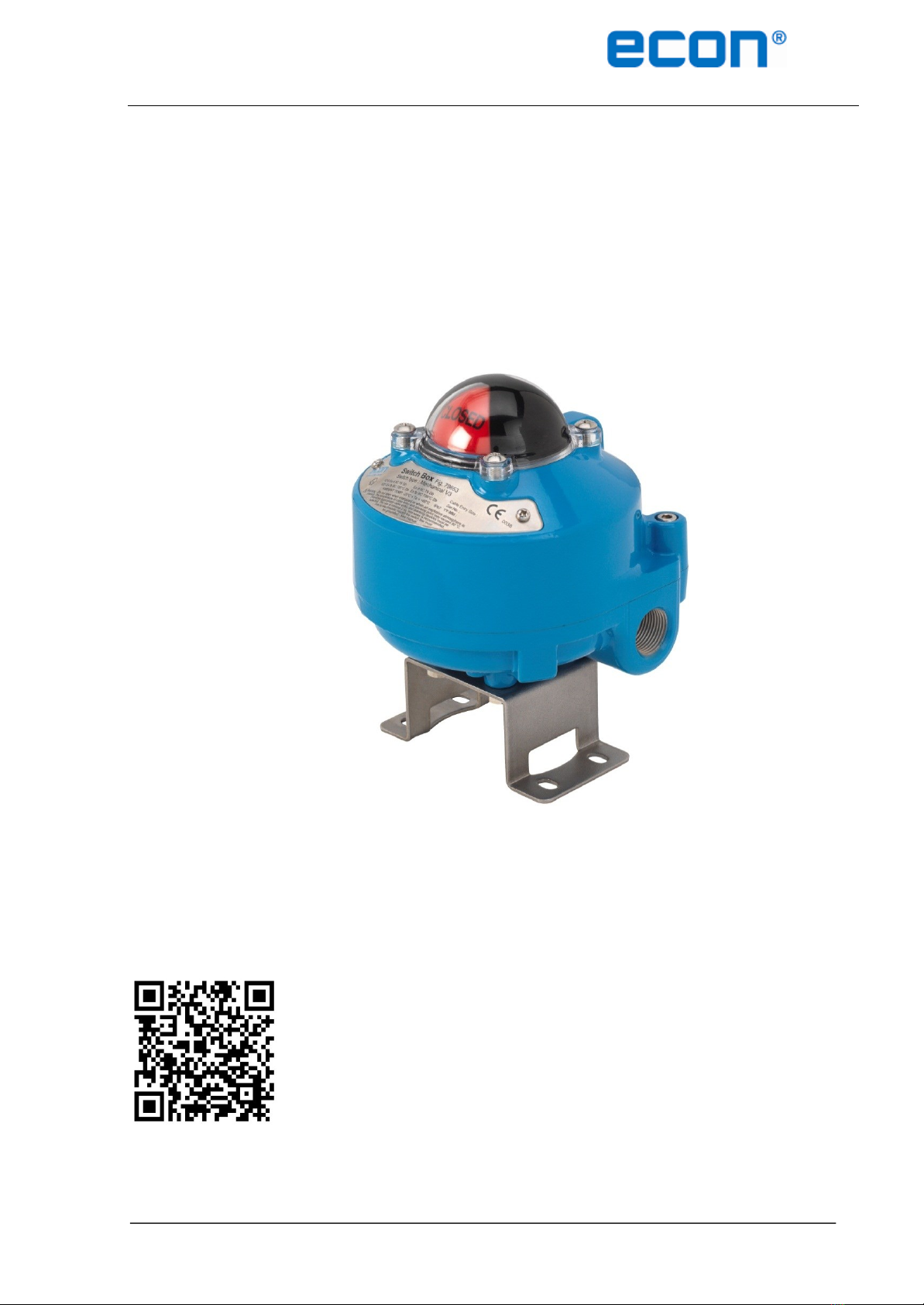
ECON limit switch Fig. 79653 www.eriks.com
Rev.0 5
6 INITIAL INSPECTION
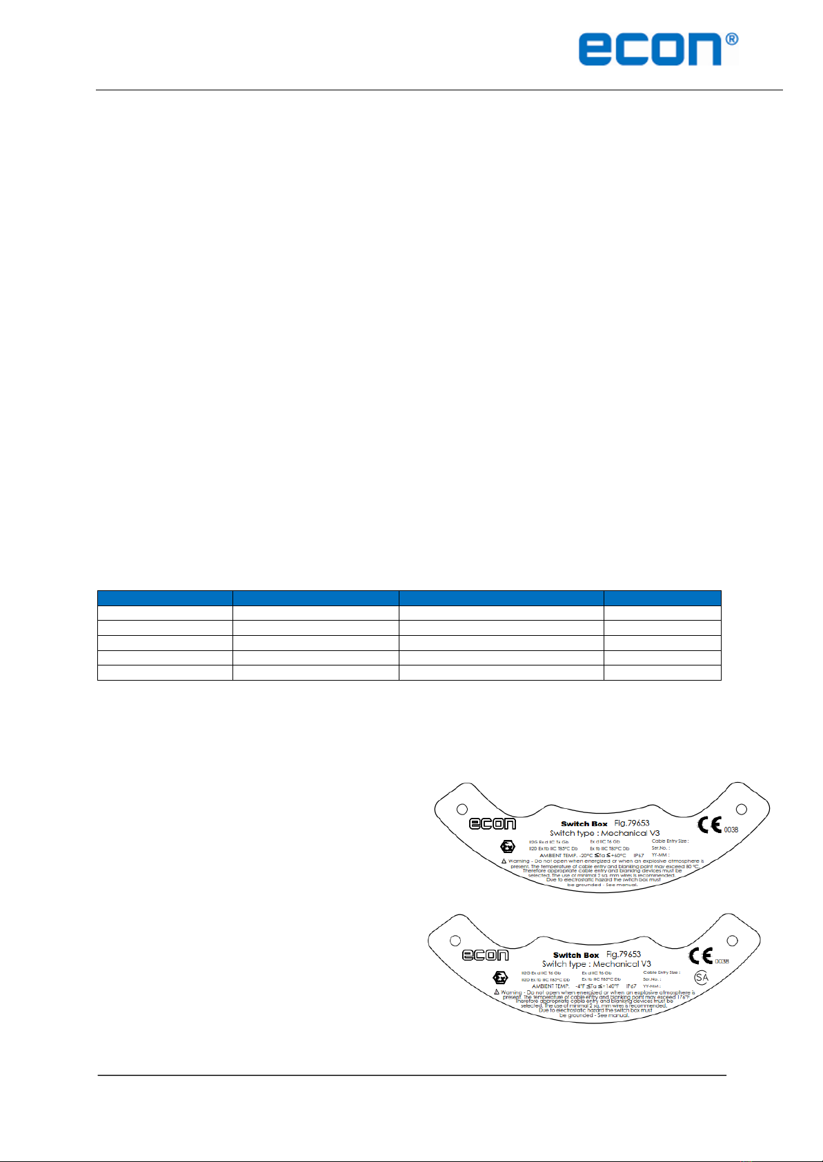
Upon on the receipt of the switch box, the user should inspect the condition of the product and ensure that the
product specification stated on the name plate matches with the order sheet.
Remove the packing wrap or cardboard box carefully. Inspect the product for any physical damage that
may have occurred during shipment.
Check the product specification of the received product. If a wrong product has been supplied, please
immediately report this to the distributing company.
7 STORAGE
Limit switch boxes must be stored in a clean, cool and dry area. The unit should be stored with the cover installed
and the conduit openings sealed. Storage must be off the floor, covered with a sealed dust protector.
8 INSTALLATION
WARNING:
Inspection and maintenance work must be performed by qualified and trained per
sonnel
When working in potentially explosive areas, the standard EN 60079-14
“Electrical Installations in Hazardous Areas” must be observed.
Work on an open limit switch box, which is under voltage, may only be performed
if there is no explosion risk.
The switch box must be grounded at all times.
Observe local and national regulations and legislation.
Flame proof enclosures may only be opened if there is no explosion risk.
CAUTION: PREVENT INJURIES
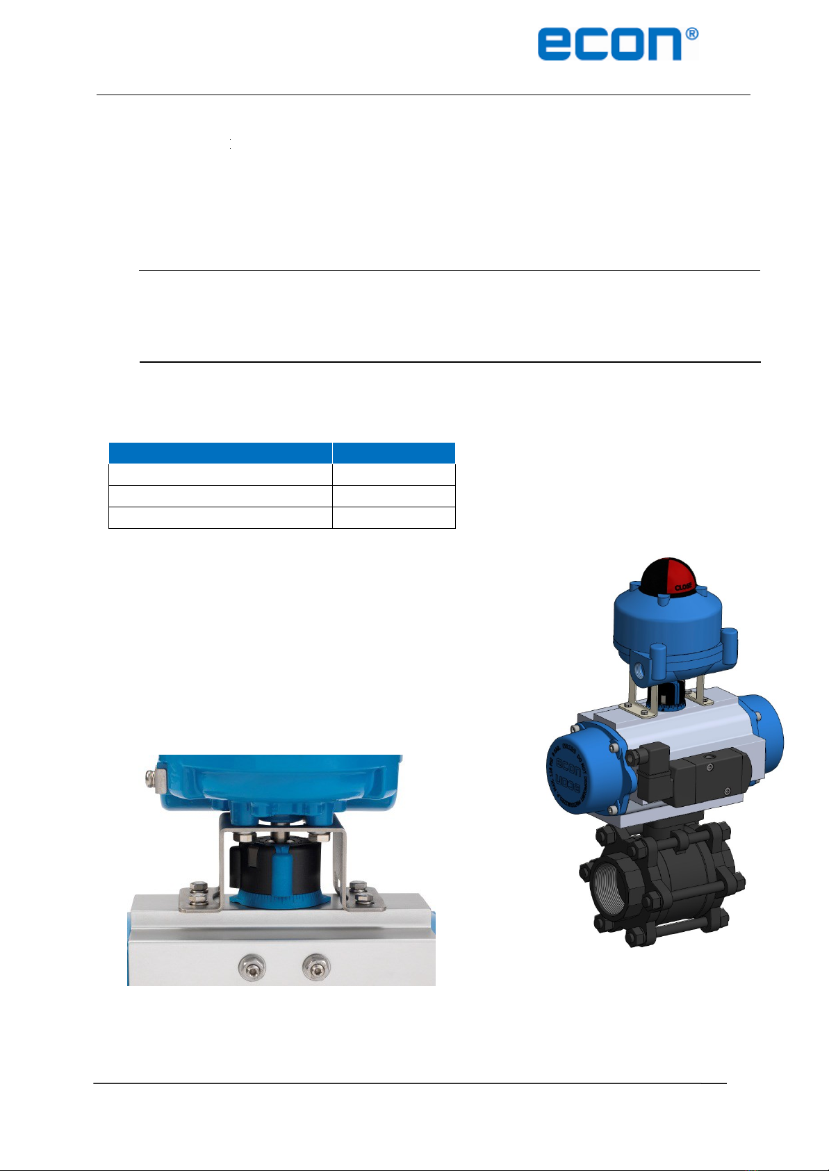
Before installing the limit switch box on the actuator, air supply and
power supply of the pilot valve must be shut off.
8.1 Installation in a potentially explosive atmosphere
Installation, commissioning, maintenance, repairs and modification work may only be performed by qualified
personnel with extensive knowledge on how to work on explosion-proof electrical equipment.
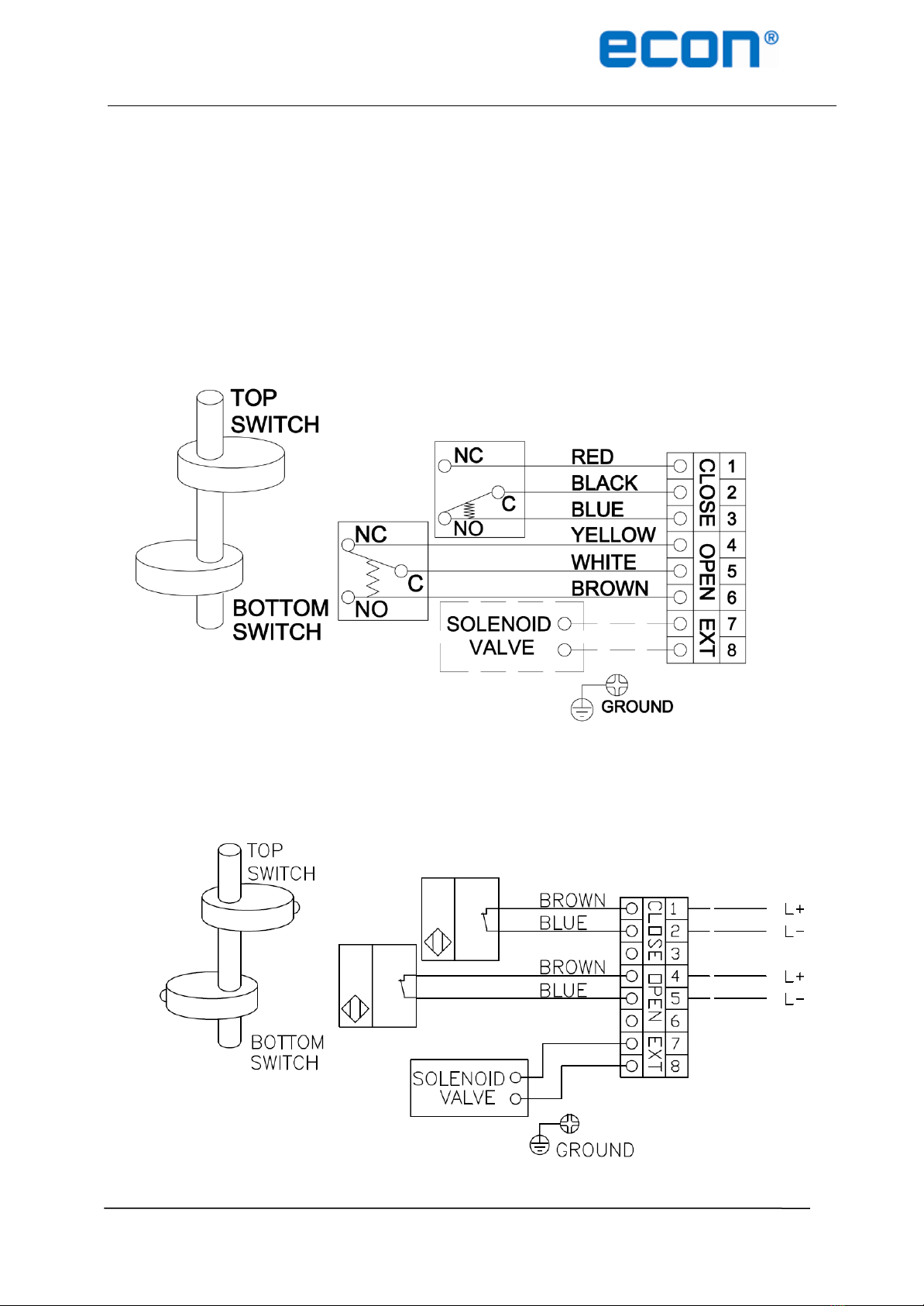
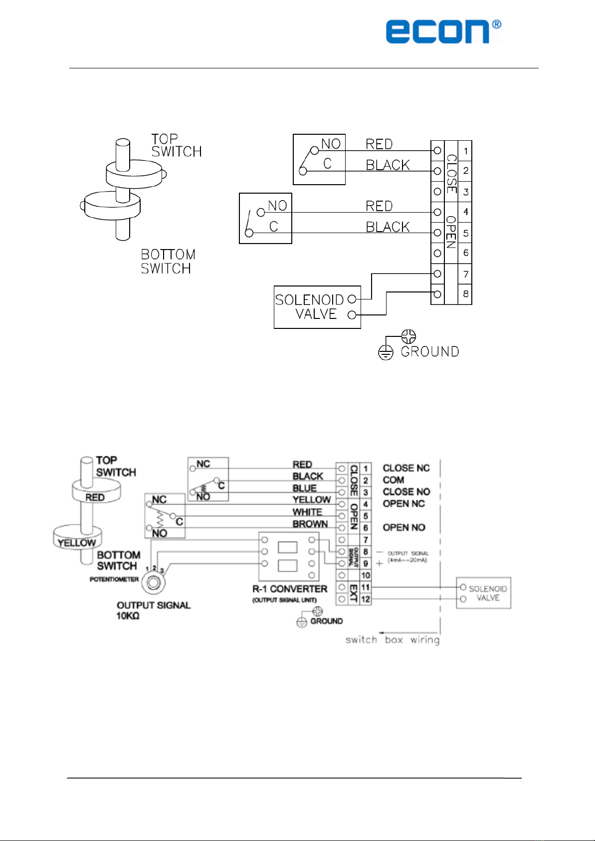
8.1.1. Cable connection
Appropriate and certified cable glands must be used and these must have suitable seals between
the cable gland and limit switch box.
Cable glands shall be suitable for the environmental conditions and shall be
flameproof certified if used in Zone 1 applications of the IEC Ex-scheme.
Cable glands must be installed with a minimum of 8 full thread lengths and the total
length of the sealing thread must be at least 8mm.
At least 2sq. mm wires must be used for wiring the limit switches or sensors.
Conduit entries that are not being used must be closed properly by the installer. Certified blanking
plugs must be used in order to maintain the explosion and flame proof properties of the limit switch
box.