manuals.online logo
Brands
  1. Home
  2. •
  3. Brands
  4. •
  5. Malibu Boats
  6. •
  7. Outdoor Light
  8. •
  9. Malibu Boats HV230WL User manual

Malibu Boats HV230WL User manual

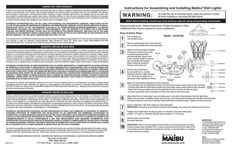
Instructions for Assembling and Installing Malibu
®
Wall Lights
To avoid the risk of electrical shock, make sure power is turned
off while installing or servicing this light fixture.
Recommended Tools: Slotted Screwdriver, Phillips Screwdriver, Pliers
(Additional tools may be required for some installations)
Easy-to-follow Steps:
Turn off power at
main breaker panel.
Remove existing light fixture
from wall and any mounting
hardware that may be present.
Attach mounting bracket to wallbox.
Thread the 2 screws (A) into
the mounting bracket provided
with this wall light. Secure with
2 lock nuts (B). (length of screws
can be adjusted as needed).
Attach mounting bracket to wall box
with screws (C).
Remove top of light fixture by turning
firmly in a counter-clockwise direction
–approximately 1/2". Lift off top and place
it in a safe place while installing the fixture.
Make wire connections using twist on wire connectors.
• Connect black wire from light fixture to black wire from power source using a twist on wire connector.
• Connect white wire from light fixture to white wire from power source using a twist on wire connector.
• Attach the house grounding wire from the light fixture to the cross bar or wall box using
thegreen grounding screw. Carefully tuck wires into wall box and cover plate.
Attach light fixture to wall using 2 cap nuts taking care not to pinch wires between wall and light fixture.
Tighten nuts securely. If installed screws are too long, or too short loosen locking nuts and adjust screw
lengths as needed. Back out set screw if needed. Rotate light fixture to desired facing. Tighten set screw securely.
Screw in light bulb. 100 watts maximum (sold separately).
IMPORTANT: Exceeding recommended maximum bulb wattage may cause over heating and risk of fire.
Replace Top of light fixture by aligning slots on underside of top
with locking tabs on light. Turn top in a clockwise direction
approximately 1/2" to lock top.
Restore power and test light
for proper operation.
IMPORTANT: After it has been determined the light is functioning properly, wall light must
be sealed using a suitable RTV or silicone caulk around the top and sides of the cover
plate to prevent water from entering the wall box. Leave the bottom un-caulked to allow
moisture to escape.
WARNING:
NOTE: Before installing, consult your local electrical codes for wiring and grounding requirements
8
7
6
5
4
3
2
1
9
10
Model HV230WL
www.intermatic.com
Fixture
HV230WLB
HV230WLA
PART #
HV230WLF
HV230WLD
HV230WLC
HV230WLE
HV230WLG
HV230WLH
HV230WLI
Wall Box
(C)
Screws
White Wire
(D)
Cap Nut
Black Wire
Twist on wire
connector
Mounting
Bracket
(A)
Mounting
Screw
(B) Lock Nut
House
Grounding
Wire
158HV12407
IMPORTANT:
For Missing/Damaged parts from
newly purchased products go to:
www.intermatic.com/warranty
or call: 1-800-492-2289.
For Replacement parts go to:
www.intermatic.com/parts
or call: 1-815-675-7000.
Note:
Matching low voltage and Solar
light fixtures are available.
See back of fixture carton.
If within two (2) years from the dateof purchase, this product fails due to a defect in material or workmanship, Intermatic Incorporated will repair or
replace it, at its sole option, free of charge. This warranty is extended to the original household purchaser only and is not transferable. This warranty
does not apply to: (a) damage to units caused by accident, dropping or abuse in handling, acts of God or any negligent use; (b) units which have
been subject to unauthorized repair, opened, taken apart or otherwise modified; (c) units not used in accordance with instructions; (d) damages
exceeding the cost of the product; (e) the finish on any portion of the product, such as surface and/or weathering, as this is considered normal wear
and tear; (f) transit damage, initial installation costs, removal costs, or reinstallation costs.
INTERMATIC INCORPORATED WILL NOT BE LIABLE FOR INCIDENTAL OR CONSEQUENTIAL DAMAGES. SOME STATES DO NOT
ALLOW THE EXCLUSION OR LIMITATION OF INCIDENTAL OR CONSEQUENTIAL DAMAGES, SO THE ABOVE LIMITATION OR EXCLU-
SION MAY NOT APPLY TO YOU. THIS WARRANTY IS IN LIEU OF ALL OTHER EXPRESS OR IMPLIED WARRANTIES. ALL IMPLIED
WARRANTIES, INCLUDING THE WARRANTY OF MERCHANTABILITY AND THE WARRANTY OF FITNESS FOR APARTICULAR
PURPOSE, ARE HEREBY MODIFIED TO EXIST ONLY AS CONTAINED IN THIS LIMITED WARRANTY, AND SHALL BE OF THE SAME
DURATION AS THE WARRANTY PERIOD STATED ABOVE. SOME STATES DO NOT ALLOW LIMITATIONS ON THE DURATION OF AN
IMPLIED WARRANTY, SO THE ABOVE LIMITATION MAY NOT APPLY TO YOU.
This warranty service is available by mailing the product, along with proof of purchase, postage prepaid to the authorized service center listed below.
This warranty is made by: Intermatic Incorporated/After Sales Service/7777 Winn Rd., Spring Grove, Illinois 60081-9698/815-675-7000
http://www.intermatic.com Please be sure to wrap the product securely to avoid shipping damage.
Si en un plazo de dos (2) años contados apartir de la fecha de compra, el producto falla debido a un defecto de material o mano de obra,
Intermatic Incorporated lo reparará oreemplazará, a opción propia, de forma gratuita. Esta garantía se aplica solamente al comprador particular
original yno es transferible. Esta garantía no se aplica en los casos siguientes: (a) daños en unidades causados por accidente, caídas oabuso
durante su manipulación, fuerza mayor o cualquier uso negligente; (b) unidades que hayan sido sometidas auna reparación no autorizada,
abiertas, desmontadas o modificadas de otraforma; (c) unidades que no se hayan usado según las instrucciones; (d) daños que excedan el
costo del producto; (e) el acabado de cualquier parte del producto, tal comola superficie yel desgaste debido ala intemperie, ya que esto se
considera como un desgaste natural; (f) daños durante el transporte, costos de instalación iniciales, costos de desmontaje o costos de reinstalación.
INTERMATIC INCORPORATED NO SERÁRESPONSIBLE DE LOS DAÑOS EMERGENTES O CONSECUENTES. ALGUNOS ESTADOS
NO PERMITEN LA EXCLUSIÓN O LIMITACIÓNDE LOS DAÑOS EMERGENTES O CONSECUENTES, POR LO QUE ES POSIBLE QUE
NO SE APLIQUE EN SU CASO LA LIMITACIÓN O EXCLUSIÓNANTERIOR. ESTA GARANTÍASUSTITUYE LAS DEMÁSGARANTÍAS
EXPLÍCITAS O IMPLÍCITAS. TODAS LAS GARANTÍAS IMPLÍCITAS, INCLUIDA LA GARANTÍADE COMERCIABILIDAD Y LA GARANTÍA
DE IDONEIDAD PARA CIERTO FIN, SE MODIFICAN AQUÍPARA EXISTIR SÓLO SEGÚNESTÁNCONTENIDAS EN ESTA GARANTÍA
LIMITADA, Y DEBEN TENER LA MISMA DURACIÓNQUE EL PERÍODO DE GARANTÍAINDICADO ARRIBA. ALGUNOS ESTADOS NO
PERMITEN LIMITACIONES DE LA DURACIÓNDE UNA GARANTÍAIMPLÍCITA, POR LO QUE ES POSIBLE QUE LA LIMITACIÓN
ANTERIOR NO SE APLIQUE EN SU CASO.
Este servicio de garantía está disponible mediante el envío por correo del producto, junto con el comprobante de compra y franqueo postal
prepagado al cetro de servicio autorzado que aparece en la lista siguienye. Esta garantía es provista por: Intermatic Incorporated/After Sales
Service/7777 Winn Rd., Spring Grove, Illinois 60081-9698/815-675-7000 http://www.intermatic.com Asegúrese de envolver bien el producto
para evitar daños durante el transporte.
Si dans un délai de deux (2) ans àcompter de la date d'achat, ce produit s'avèredéfectueux pour vice de matériau ou de fabrication, Intermatic
Incorporated le réparera ou le remplacera, la décision appartenant Intermatic Incorporated, sans frais. Cette garantie ne concerne que l'acheteur
initial et n'est pas transférable. Cette garantie ne couvre pas :(a) dommages occasionnés par accident, chute ou abus lorsde manipulations, cas
fortuits ou toute négligence ; (b) unités ayant subi àdes réparations non autorisées, ouvertes, démontées ou modifiées d'une quelconque façon ;
(c) unités qui ne sont pas utiliséesconformément aux instructions ; (d) dommages supérieurs au coût du produit ;(e) la finition d'une partie du produit,
telle que les rayures de surface et/oule vieillissement climatique qui sont considérés comme une usure normale ; (f) dommages ayant lieu pendant
le transport, frais initiaux d'installation, de désinstallation ou de réinstallation.
INTERMATIC INCORPORATED N'ENDOSSE AUCUNE RESPONSABILITÉQUANT AUX DOMMAGES ACCESSOIRES OU INDRECTS.
CERTAINES PROVINCES NE PERMETTENT PAS D'EXCLUSIONS OU DE LIMITATIONS AUX DOMMAGES ACCESSOIRES OU
CONSÉCUTIFS, LA LIMITE INDIQUÉECI-DESSUS PEUT NE PAS VOUS CONCERNER. CETTE GARANTIE CI-PRÉSENTES REMPLACE
TOUTES AUTRES GARANTIES EXPRESSES OU TACITES. TOUTES LES GARANTIES TACITES Y COMPRIS LA GARANTIE DE
COMMERCIALISATION ET CELLE D'ADAPTABILITÉ À DES FINS PARTICULIÈRES SONT MODIFIÉES CI-PRÉSENTES POUR
N'EXISTER QUE TELLES QUELLES DANS CETTE GARANTIE LIMITÉEET AURONT LA MÊME DURÉEDE VALIDITÉQUE LA PÉRIODE
DE GARANTIE INDIQUÉECI-DESSUS. CERTAINES PROVINCES NE PERMETTENT PAS DE LIMITATIONS AUX TERMES DE LA DURÉE
DE LA GARANTIE TACITE, LA LIMITE INDIQUÉECI-DESSUS PEUT NE PAS VOUS CONCERNER.
Ce service sous garantie est disponible par en expédiant le produit par la poste, avec une preuve d’achat, affranchissement pré-payé au centre
de service autorisé indiqué plus bas. Cet garantie fait par: Intermatic Incorporated/After Sales Service/7777 Winn Rd., Spring Grove, Illinois 60081-
9698/815-675-7000 http://www.intermatic.com Veiller à bien emballer le produit afin qu'il ne subisse aucun dommage pendant l'expédition.
GARANTÍA LIMITADA DE DOS AÑOS
GARANTIE LIMITÉE DE DEUX ANS
LIMITED TWO YEAR WARRANTY
AUTHORIZED SERVICE CENTER / CENTRO DE SERVICIO AUTORIZADO / CENTRE DE SERVICE ABRÉÉ
Intermatic Incorporated
After Sales Service
7777 Winn Road • Spring Grove, IL 60081-9698Ê
8
7
6
5
4
3
2
1
9
10
8
7
6
5
4
3
2
1
9
10
Instructions pour assembler et installer les lampes murales Malibu
®
Pour éviter tout risque de choc électrique, assurez-vous de
couper le courant en installant ou réparant cette lampe.
Outils recommandés : Tournevis enchoché, Tournevis Philips, Pinces
(D’autres outils pourraient être nécessaires pour certaines installations)
Étapes faciles à suivre :
Coupez le courant au panneau
disjoncteur principal.
Retirez la lampe actuelle du mur
et toute autre quincaillerie qu’il
pourrait y avoir.
Installez la ferrure de montage à
la boîte de jonction. Enfilez les 2
vis (A) dans la ferrure de montage
fournie avec cette lampe murale.
Fixez avec 2 écrous de blocage (B).
(la longueur des vis s’ajuste au
besoin). Fixez la ferrure de montage
à la boîte de jonction avec des vis (C).
Retirez le dessus de la lampe en tournant
fermement dans le sens contraire des
aiguilles d’une montre d’environ 1/2 po.
Soulevez le dessus et placez-le en
sécurité tandis que vous installez la lampe.
Faites les connexions par fil à l’aide des capuchons de connexion.
• Connectez le fil noir de la lampe au fil noir de la source d’énergie à l’aide d’un
capuchon de connexion.
• Connectez le fil blanc de la lampe au fil blanc de la source d’énergie à l’aide d’un
capuchon de connexion.
• Fixez le fil de mise à la terre résidentiel de la lampe à la traverse ou à la boîte de
jonction à d’une vis de mise à la terre verte. Rangez bien les fils dans la boîte de
jonction et la plaque de recouvrement.
Fixez la lampe au mur à l’aide des 2 écrous borgnes en ne pinçant pas les fils entre le mur et la lampe. Resserrez bien les écrous. Si les
vis installées sont trop longues ou trop courtes, desserrez les écrous de blocage et ajustez la longueur au besoin. Retirez un peu la vis de
réglage au besoin. Tournez la lampe pour qu’elle soit dans la direction voulue. Resserrez bien la vis de réglage.
Mettez l’ampoule. 100 watts maximum (vendue séparément). IMPORTANT : Dépasser le wattage maximum recommandé pour l’ampoule
pour provoquer une surchauffe et un risqué d’incendie.
Replacez le dessus de la lampe en alignant les fentes sous le dessus
avec les onglets de verrouillage de la lampe. Tournez le dessus
dans le sens des aiguilles d’une montre d’environ 1/2 po pour verrouiller.
Remettez le courant et essayez la lampe pour
vérifier si elle fonctionne.
IMPORTANT : Après avoir vérifié son fonctionnement, scellez la lampe murale
à l’aide d’un produit de vulcanisation à la température de la pièce ou du mastic
de silicone autour du dessus et des côtés de la plaque pour éviter que
l’eau ne pénètre dans la boîte de jonction. N’intempérisez pas le dessous
pour laisser échapper l’humidité.
AVERTISSEMENT :
REMARQUE : Avant d’installer,consultezvos codes d’ lectricit locauxpour connaître les exigences de câblage
et de mise à la terre.
Modèle HV230WL
Instrucciones para armar e instalar las lámparas de paredMalibu
®
Para evitar el riesgo de shock eléctrico, verifique que la alimentación
de energía esté apagada mientras instala o repara la lámpara.
Herramientas recomendadas: Destornillador plano, Destornillador cruciforme,
Pinzas (Podría necesitar herramientas adicionales para algunas instalaciones)
Pasos sencillos:
ADVERTENCIA:
NOTA:Antes de instalar,consulte el código el ctrico local para determinar los requisitos de cableadoy
conexión a tierra.
Modelo HV230WL
Desconecte la alimentación en el panel
principal de interruptores de circuitos.
Retire la lámpara existente de la
pared y cualquier otro accesorio de
instalación que pueda estar presente.
Fije el soporte de montaje a la caja de
pared. Atornille los 2 tornillos (A) en
el soporte de montaje que viene con
esta lámpara de pared. Asegure
con dos tuercas de seguridad (B).
(la longitud de los tornillos se puede
ajustar como sea necesario). Fije el
soporte de montaje a la caja de pared
con los tornillos (C).
Gire la parte superior de la lámpara en
sentido contrario a las agujas del reloj
aproximadamente 1/2 pulgada para retirarla.
Levante la parte superior de la lámpara y colóquela
en un lugar seguro mientras instala la lámpara.
Haga las conexiones de los cables utilizando tuercas para cables.
• Conecte el cable negro de la lámpara con el cable negro que proviene
dela fuente de alimentación utilizando una tuerca de cable.
• Conecte el cable blanco de la lámpara con el cable blanco que proviene
dela fuente de alimentación utilizando una tuerca de cable.
• Conecte el cable de tierra de la lámpara con la barra de cruce o la caja de pared utilizando el tornillo
detierra verde. Introduzca los cables cuidadosamente en la caja de pared y coloque la cubierta de la caja.
Fije la lámpara a la pared utilizando las 2 tuercas de tapa y teniendo cuidado de no apretar demasiado los cables
entre la pared y la lámpara. Ajuste las tuercas firmemente. Si los tornillos instalados son muy largos o muy cortos,
afloje las tuercas de seguridad y apriete los tornillos tanto como sea necesario. Saque el tornillo de ajuste si es
necesario. Gire la lámpara hasta la posición deseada. Ajuste el tornillo de ajuste para asegurarlo.
Atornille el bombillo. Máximo de 100 vatios (se vende por separado). IMPORTANTE:El uso de bombillos
que excedan el vatiaje máximo recomendado pueden causar sobrecalentamiento y riesgo de incendio.
Vuelva a colocar la parte superior de la lámpara mediante la alineación de las ranuras
que se encuentran debajo de su parte lateral con las pestañas de seguridad de la
lámpara. Gire la parte superior de la lámpara en dirección de las agujas del reloj
aproximadamente media pulgada para asegurarla.
Conecte nuevamente la alimentación y pruebe el correcto
funcionamiento de la lámpara.
IMPORTANTE:Una vez comprobado el correcto funcionamiento de la lámpara, la
lámpara de pared se debe sellar utilizando un RTV adecuado o material de silicona
para calafatear en la parte superior de la placa de cubierta para evitar la entrada de
agua a la caja de pared. Deje la parte final sin calafatear para que se pueda secar.
HV230WLB
HV230WLA
PIEZA #
HV230WLF
HV230WLD
HV230WLC
HV230WLE
HV230WLG
HV230WLH
HV230WLI
(D)
Tuerca de tapa
Lámpara
Caja de
pared
(C)
Tornillos
Cable blanco
Cable negro
Tuerca de cable
(A)
Tornillo
de montaje
(B)Tuerca de
seguridad
Cable de
tierra de
casa
Soporte
de montaje
IMPORTANTE:
Si el producto que acaba de adquirir está
incompleto o tiene piezas dañadas,
notifique el problema a través de:
www.intermatic.com/warranty
o llame al: 1-800-492-2289.
Para información sobre repuestos, visite:
www.intermatic.com/parts
o llame al: 1-815-675-7000.
Nota: Se encuentran disponibles lámparas
de bajo voltaje y lámparas solares
complementarias. Véase el dorso de la
caja de la lámpara.
IMPORTANT:
En cas de pièces manquantes /
endommagées dans des produits tout
neufs, allez auÊ:
www.intermatic.com/warranty ou appelez
le : 1-800-492-2289. Pour des pièces de
rechange, allez auÊ:
www.intermatic.com/parts ou appelez leÊ:
1-815-675-7000.
Note : Aussi offerts comme dispositif solaire
et basse tension assortis. Voir l’arrièredu
carton du dispositif.
HV230WLB
HV230WLA
PIÈCE #
HV230WLF
HV230WLD
HV230WLC
HV230WLE
HV230WLG
HV230WLH
HV230WLI
(D)
Écrou borgne
Dispositif
Boîte de
jonction
(C)
Vis
Fil noir
Capuchon
de connexion
Ferrure de
montage
(A)
Vis de
montage
(B) Écrou de
blocage
Vis
de mise à
la terre
résidentielle
Fil blanc

Other Malibu Boats Outdoor Light manuals

Malibu Boats CS290SM User manual

Malibu Boats

Malibu Boats CS290SM User manual

Malibu Boats ML100THBM User manual

Malibu Boats

Malibu Boats ML100THBM User manual

Malibu Boats 8301-9501-01 User manual

Malibu Boats

Malibu Boats 8301-9501-01 User manual

Malibu Boats 8308-9603-01 User manual

Malibu Boats

Malibu Boats 8308-9603-01 User manual

Malibu Boats LZ415SM User manual

Malibu Boats

Malibu Boats LZ415SM User manual

Malibu Boats HV402PLK User manual

Malibu Boats

Malibu Boats HV402PLK User manual

Malibu Boats CS290 User manual

Malibu Boats

Malibu Boats CS290 User manual

Malibu Boats HV402WLK User manual

Malibu Boats

Malibu Boats HV402WLK User manual

Malibu Boats 8401-9303-01 User manual

Malibu Boats

Malibu Boats 8401-9303-01 User manual

Malibu Boats LZ701 User manual

Malibu Boats

Malibu Boats LZ701 User manual

Malibu Boats CL4 User manual

Malibu Boats

Malibu Boats CL4 User manual

Malibu Boats HV230PL User manual

Malibu Boats

Malibu Boats HV230PL User manual

Malibu Boats CL280 User manual

Malibu Boats

Malibu Boats CL280 User manual

Malibu Boats LZ1SM User manual

Malibu Boats

Malibu Boats LZ1SM User manual

Malibu Boats C330OB Manual

Malibu Boats

Malibu Boats C330OB Manual

Malibu Boats CL280V User manual

Malibu Boats

Malibu Boats CL280V User manual

Malibu Boats CL309V User manual

Malibu Boats

Malibu Boats CL309V User manual

Malibu Boats LZ7FC2 User manual

Malibu Boats

Malibu Boats LZ7FC2 User manual

Malibu Boats CL191 User manual

Malibu Boats

Malibu Boats CL191 User manual

Malibu Boats HV401WL User manual

Malibu Boats

Malibu Boats HV401WL User manual

Malibu Boats HV401PL Operating instructions

Malibu Boats

Malibu Boats HV401PL Operating instructions

Malibu Boats CS14SM Manual

Malibu Boats

Malibu Boats CS14SM Manual

Malibu Boats CL305P User manual

Malibu Boats

Malibu Boats CL305P User manual

Popular Outdoor Light manuals by other brands

Inowel 22529 Intended use

Inowel

Inowel 22529 Intended use

MOOD YAELLE Installation Notice

MOOD

MOOD YAELLE Installation Notice

Marecoluce Indus Series Use and maintenance instructions

Marecoluce

Marecoluce Indus Series Use and maintenance instructions

Velleman CLC4 quick start guide

Velleman

Velleman CLC4 quick start guide

iGuzzini STREET S NEMA installation instructions

iGuzzini

iGuzzini STREET S NEMA installation instructions

Conrad 56 26 54 operating instructions

Conrad

Conrad 56 26 54 operating instructions

LIGMAN HA-60209-S installation manual

LIGMAN

LIGMAN HA-60209-S installation manual

LEDDOO QUADRA TL-1 user manual

LEDDOO

LEDDOO QUADRA TL-1 user manual

Inspire Murray instruction manual

Inspire

Inspire Murray instruction manual

LUTEC 6925601345 manual

LUTEC

LUTEC 6925601345 manual

nordlux Mento Mounting instruction

nordlux

nordlux Mento Mounting instruction

Vimar Idea 16450 quick start guide

Vimar

Vimar Idea 16450 quick start guide

BALTENSWEILER IRIO S CASAMBI ready Mounting and operating instructions

BALTENSWEILER

BALTENSWEILER IRIO S CASAMBI ready Mounting and operating instructions

Digital Watchdog NightWatch DW-ILWLIPM quick start guide

Digital Watchdog

Digital Watchdog NightWatch DW-ILWLIPM quick start guide

LIGMAN LADOR 5 installation manual

LIGMAN

LIGMAN LADOR 5 installation manual

LIGMAN CAPSULE 5 installation manual

LIGMAN

LIGMAN CAPSULE 5 installation manual

Faro Barcelona PICCOLA 70246 quick start guide

Faro Barcelona

Faro Barcelona PICCOLA 70246 quick start guide

TEKA ILLUMINATION TOWER BOLLARD installation instructions

TEKA ILLUMINATION

TEKA ILLUMINATION TOWER BOLLARD installation instructions

manuals.online logo
manuals.online logoBrands
  • About & Mission
  • Contact us
  • Privacy Policy
  • Terms and Conditions

Copyright 2025 Manuals.Online. All Rights Reserved.