MAM RS3 User manual

Operation
Manual
RS3

Introduction
The resonator is a special Filter, its operation is based on the same circuit of the
legendary synthesizer PS3100 / PS3300 by Korg. The purely analogue filters are
realized by means of photocouplers (so-called "Vactrols"), which are characterized
by low noise, a high superconducting strength and a slow response.
Possible applications:
• filter sweeps
• Phaser / Flanger-like effects
• dynamic sound changes
Principles Of Operation
The input signal (mono) passes through 3 parallel bandpass filters, whereby the
intrinsic sound of the resonator is created by the high Q (resonance) of this
bandpass filter. Impressive stereo effects can be achieved by modulating the
resonance frequencies with different LFO signals. Dynamic sound changes result
from the ENV modulation. The bandpass filters are controlled by envelope
followers, which react to different frequency ranges. In addition, an external
voltage can be connected as a modulation source.
é

Connections of the RS3
• $&ýìëý92/7
External Power Supplyýõ12 Volt, AC, 700 mA)
•INPUT (Front), IN (Rear)
Audio input of the RS3. If both sockets are connected, only the input
on the front will be active.
• Man/EXT IN (Front), Modulation (Rear)
An external voltage (0-10V) for common modulation of the bandpass
frequencies. If both sockets are connected, only the input on the front side is
active.
• OUT (Rear)
Stereo Output of the RS3
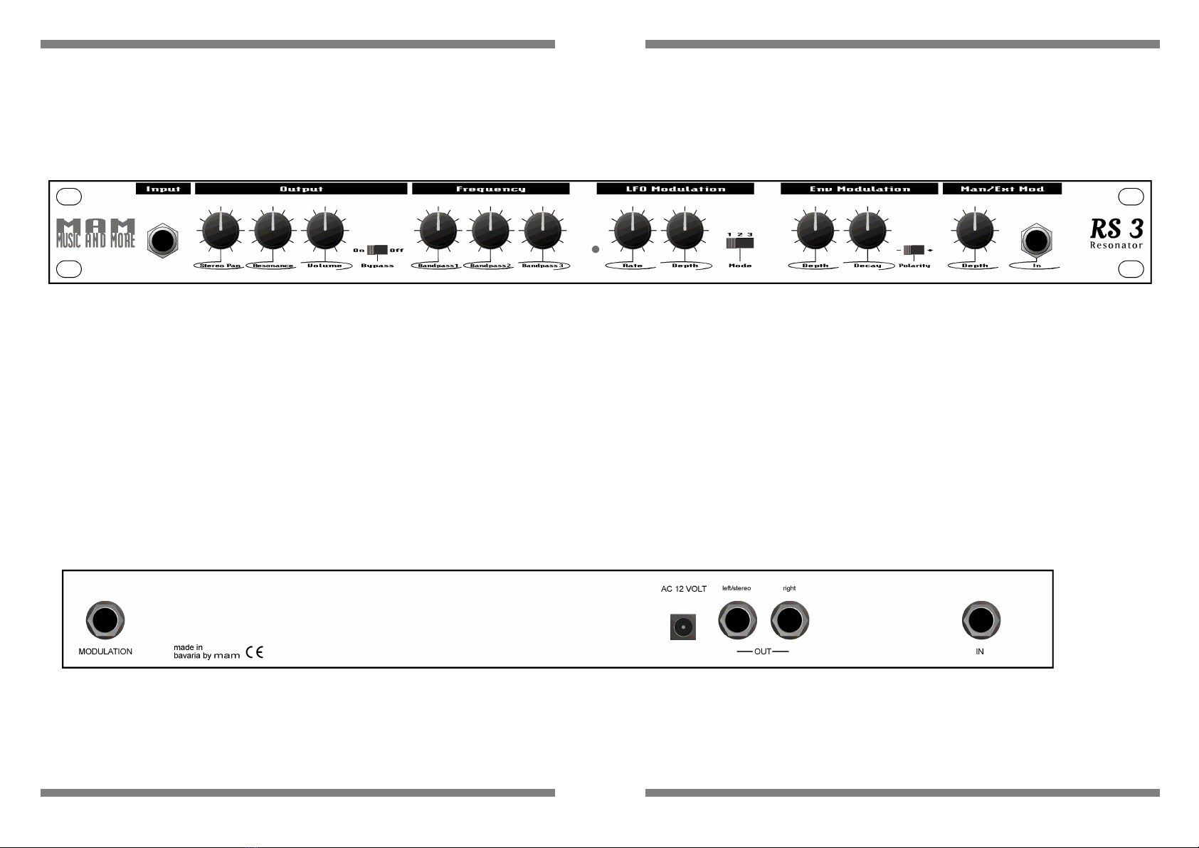
Controls Of The RS3
Front View
5•FNDQVLFKW
Input:
Stereo Pan:
Resonance:
Volume:
Bypass:
Frequency:
LFO Rate:
LFO Depth:
LFO Mode:
ENV Modulation:
ENV Depth:
ENV Decay:
ENV Polarity:
Man/Ext Input:
Mod Input:
Mod Input:
Audio Mono Input
This knob adjusts the stereo panning of Bandpass1 and Bandpass3. Bandpass2 is distributed equally to the right and left output.
Determines the ratio between the original and the effected signal
Volume at the output of the RS3 (Bypass OFF)
ON: The input signal is switched to the output without change. OFF: The effect signal is present at the output of the RS3.
With these controllers the center frequency of the bandpass 1,2 and 3 can be adjusted individually.
Speed of the LFO (0.01Hz-2Hz)
Intensity of LFO modulation
Mode 1: LFO1 -> Bandpass 1.2 3 / Mode 2: LFO1 -> Bandpass 1.3; LFO2 -> Bandpass 2 / M ode 3: LFO1 -> Bandpass 1; LFO1 inverted -> bandpass 2; LFO2 -> Bandpass3
Envelope-Follower1 (LOW) -> Bandpass1, Envelope-Follower2 (MID) -> Bandpass2, Envelope-Follower2 (HIGH)
Regulates the strength of the ENV modulation for all band pass collectively.
The envelope decay time can be changed with the help of the decay control.
(+) Envelope followers shift bandpass frequencies up. (-) The envelope followers shift the bandpass frequencies down.
The operation of this controller depends on whether the external modulation input is connected or not.
Input unconnected: Manual control of the bandpass frequencies 1,2 and 3.
Input connected: The bandpass frequencies are now modulated by an external control voltage.
02'8/$7,21ã
$&ýìëý92/7
OHIWî6WHUHRã
ULJKWã
,QSXWã
Connection. an external voltage (0-10V) for common modulation of the bandpass frequencies. If both sockets are connected, only the input on the front side is active.
Anschlur. des externen Netzteils (12Volt, AC, 700 mA)
Connection. the external power supply (12V, AC, 700mA)
Right mono output
Audio mono input
+;,;.;:;+
F.-equency
AC 12 VOLT left/stereo right
MODULATION
~a"v~~i~n
by
mam
( E
-OUT-
Enu
Hoduta.•"llon
IN
0
RS3
R
eso
nator
0

• Output
•Stereo Pan
Use this knob to adjust the stereo panning of Bandpass1 and Bandpass3.
Bandpass2 is equally distributed on the right and left outputs.
Knob position left: Bandpass1 -> left, Bandpass3 -> right Knob
position right: Bandpass1 -> right, Bandpass3 -> left Knob
position middle: Mono mode
•Resonance
Determines the ratio between the original and the effect signal
•Volume
Adjusts the volume at the output of the RS3 (Bypass OFF)
• Bypass
ON: The input signal is switched to the output without change.
OFF: The effect signal is present at the output of the RS3.
• Frequency
With these controllers, the center frequency of the bandpass filters 1, 2 and 3
can be set individu- ally.
• LFO Modulation
‡RATE
Speed of the LFO (0.01Hz-2Hz)
‡Depth
Intensity of LFO modulation
‡ Mode
The RS3 has 3 different LFO sources: LFO1, LFO2 and LFO1 inverted. LFO 1
and 2 have a sawtooth waveform, but have a different speed (LFO 2 is about
30% faster than LFO1.
With the mode switch, these are assigned to the individual bandpasses in
various combinations, which allows different stereo effects to be achieved
(maximum stereo depth in mode 3).
Mode 1: LFO1 -> Bandpass 1,2 3
Mode 2: LFO1 -> Bandpass 1,3
LFO2 -> Bandpass 2
Mode 3: LFO1 -> Bandpass 1
LFO1 inverted -> Bandpass 2
LFO2 -> Bandpass3
• ENV Modulation
The RS3 has 3 mutually independent envelope followers that respond to
different frequency ranges (LOW, MID and HIGH) of the input signal. Envelope
followers act on the bandpass as follows:
Envelope-Follower1 (LOW) -> Bandpass1
Envelope-Follower2 (MID) -> Bandpass2
Envelope-Follower2 (HIGH) -> Bandpass3
The bandpass frequencies thus change depending on the sound and
dynamics of the input signal. This effect is particularly impressive in stereo
mode (stereo pan left or right).
• Depth
Regulates the strength of the ENV modulation for all band pass
collectively.
· Decay
Evelope followers respond very quickly to changes in the input signal (short
attack time). The decay time (Decay) can be changed with the help of the decay
control.
‡ Polarity
+: The envelope followers shift the bandpass frequencies up.
- : The envelope followers shift the bandpass frequencies down.
• MAN/EXT Modulation
The operation of this controller depends on whether the external modulation
input is connected or not.
• Input not connected:
Manual control of bandpass frequencies 1,2 and 3.
• Input connected:

The bandpass frequencies are now modulated by an external control voltage.
The Man controller has the following effect in this case:
Controller position middle: External voltage without effect
Control position right: Modulation of the bandpass frequencies upwards. Left
control position: Modulation of the bandpass frequencies down
Important Safety instructions
1. Read all instructions before using the unit.
2. Never use the device near water, e.g. next to a bath, a sink, a cooking area, in a
wet basement or next to a swimming pool.
3. This equipment, in combination with an amplifier and headphones or speakers,
may produce sound levels that may result in permanent hearing damage. Avoid
too high or unpleasant loud sounds over a long period of time. If you notice a
hearing damage or ear external ulcer, consult an ear specialist.
4. The appliance should be installed in such a way that sufficient fresh air supply is
always ensured.
5. The appliance should not be near sources of heat, e.g. Radiators, oven or other
heat-generating devices are placed.
6. The device may only be connected to standardized sockets.
7. Place the unit so that no objects, flims or dust can enter the unit interior.
8. If the unit is not used for a long period of time, unplug the external power
adapter from the mains.
9. The unit should be serviced by a qualified professional if:
•the external power supply is damaged or
•objects or flosses have entered the device or
•the device was in the rain or
•the device has been damaged as a result of a fall or
•The device should be disturbed in its normal functioning.
Do not do repairs yourself, but have them done by a qualified technician.
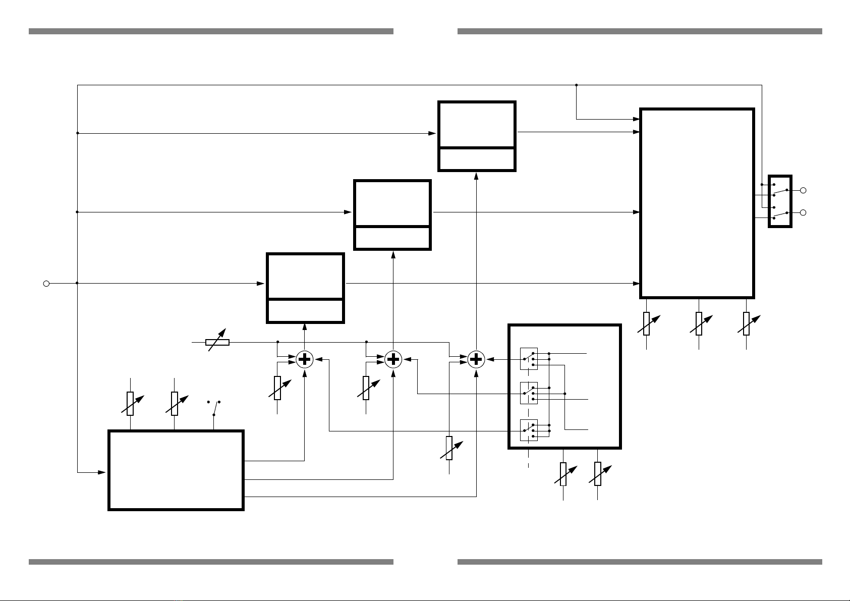
RS3 block diagram
,1
5$7(
%DQGSDVVë
)5(48(1&<
&21752/
,1 287
(19(/23(ý)2//2:(5
/2:
0,'
+,*+
'(37+ 32/$5,7<'(&$<
òð
%DQGSDVVê
)5(48(1&<
&21752/
,1 287
%DQGSDVVì
)5(48(1&<
&21752/
,1 287
%DQGSDVVýì %DQGSDVVýë
%DQGSDVVýê
0$1î(;7 /)2
/)2ë
/)2ìýð
/)2ìýò
A
ì
ë
ê
ì
ë
ê
ì
ë
ê
'(37+
02'(
287387
67(5(2
3$1ýõìñêô
5(621$1&(
92/80(
287ý5
287ý/
%<3$66
• •
Table of contents


