AMS AMX 1224 USB User manual

USER MANUAL /MANUAL DE USO
AMX 1224 USB
Rev. 14.03.01

4.8.12 Mono and 4 stereo Input Channels with silver plated XLRs and balanced Line Inputs
Ultra-low noise discrete Mic Preamps with +48 V Phantom Power
Extremely high headroom - offering more dynamic range
Balanced Inputs for highest signal integrity
Ultra-musical 3-band EQ on all mono channels
Peak LEDs on all channels with MUTE function
2 Aux Send per channel for external effects and monitoring
24-Bit of the effect system inside
Separate Master Mix, Headphone Outputs
2-Track Inputs assignable to Master Mix
Highly accurate 10 segment Bargraph Meters
SAFETY INSTRUCTIONS
CAUTION: To reduce the risk of electrical shock, do not remove
the cover (or back). No user serviceable parts inside;
refer servicing to qualified personnel.
WARNING: To reduce the risk of fire or electrical shock, do not
expose this appliance to rain or moisture.
CAUTION
RISK OF ELECTRIC SHOCK
DO NOT OPEN
This symbol, wherever it appears, alerts
you to the presence of uninsulated
dangerous voltage inside the enclosure
- voltage that may be sufficient to con-
stitute a risk of shock.
This symbol, wherever it appears, alerts
you to important operating and mainte-
nance instructions in the accompanying
literature. Read the manual.
AMX Series - 1 - User Manual / Manual de uso

A. INPUT CHANNEL SECTION
1
2
3
4
5
6
7
8. STEREO LINE INPUTS
These 1/4” jacks may be driven by stereo or mono, balanced or unbalanced
sources.
7. MONO LINE INPUTS
These 1/4” jacks share circuitry(but not phantom power) with the mice
preams and may be driven by balanced or unbalanced sources.
5. GAIN
For setting preamplifier gain of corresponding channel to present the
overdrive/distortion at high level inputs or unwanted back ground noise
because of low input drive.
6. LOW CUT
Each channel with a mic input has a low cut switch that cuts the bass
frequency below 100Hz,at a rate of 18dB per octave. All mic inputs are
affected, as well as the line inputs of the mono channels.
3. LINE INPUT
The unbalanced Mic input is provided for the use of an unbalance mic and
is designed to accept an unbalanced high impedance input signal.
(This use for connection Deck, Turntable, Keyboard etc..)
1. MIC INPUTS
You can plug in almost any kind of mic that has a standard XLR male mic
connector.
4. INSERT
The INSERT is a break point in the input channel signal path. It allows
the signal to be taken out from the mixer, through an external equipment
such as a compressor, and then back to the mixer to continue the final
mix output.
8
2. LINE/HI-Z SWITCH
To connect a guitar directly to the mixer without using a DI Box, press this
switch in first;then connect the output from the guitar to channel I’s 1/4 TRS
input..
AMX Series - 2 - User Manual / Manual de uso

11. LOW EQ
This control gives you up to 15dB boost or cut below 80Hz.The circuit is
flat at the center detent position.
12. AUX MON
These knobs tap a portion of each channel’s signal to set up a nice monitor
mix feeding stage monitors, independent of the main mix.
13. AUX FX
These knobs tap a portion of each channel’s signals to set up a nice FX
mix feeding the internal FX processor, and to feed external processors
via the FX output.
14. PAN
To balance the signals of the left/right of the corresponding channel.
16. CHANNEL FADER
These faders control the channel’s level from off, on up to 10dBof additional
gain. The mono channels have mono faders, and the hybrid and stereo
channel use stereo faders.
15. MUTE / PEAK
Press this switch in to mute the channel in the main mix. Press the switch
up to use as PEAK, this LED indicates a signal level at the insert return
point, premaster fader, it illuminates at approximately 5dB below clipping.
10
10. MID EQ
This knob provides 15dB of boost or cut, centered at 2.5Khz,also flat at
the center detent.
9. HI EQ
This control gives you up to 15dB boost or cut above 12kHz,and it’s flat at
the detent.
16
14
13
12
9
11
15
AMX Series - 3 - User Manual / Manual de uso

B. MASTER SECTION
18
17
21. POWER LED
This LED comes on when the mixer is plugged
into the AC mains supply, and the rear panel
power switch is on.
22. METERS
These meters have 2 columns of 10LEDs each, they indicate the stereo signal strength of the main mix after
the main fader.
20. PHANTOM SWITCH
Press in this switch to add phantom power to
all the XLR microphone inputs of the mixer, the
LED turns on when it’s working.
19. STEREO GRAPHIC EQ
This 7-band graphic equalizer adjusts the main
mix output.
17. LINE SWITCH (3.5)
Press this button while connecting the LINE IN
port for the stereo input signal.
18. BAL
The BAL control sends continuously variable
amounts of the post fader signal to either the
left or right main buses. In the center position
equal amounts of signal are sent to the left and
right busses.
19 20 21
22
23
24
25
23. PRESET DISPLAY
This display show the number of the currently selected effects preset..
24. PRESET AND TAP DELAY
Rotate this knobs to increase or decrease the number of the preset. When you stop the rotation, that preset
will be loaded.and become operation.. The current preset number is show in the display. The knob also offers
a tap delay function for the preset 17 to 24. The LED will flash in time with the new tap delay time.
25. INTERNAL FX MUTE and LED
When engaged, the internal effects processor is muted,and the adjacent LED will come on..The footswitch
connection become disabled and the footswitch can’t be used to mute or un-mute the effects.
26
26. USB / S.D. JACK
This is USB / SDCARD Jack.
AMX Series - 4 - User Manual / Manual de uso

PLAY/PAUSE: (PLAY/PAUSE Button)
Push this button to PLAY/PAUSE, while pushing
it continually to change the playing mode: MP3 or
WAV.
PREV: (PREV Button)
Push this button for the previous song, while pushing
it continually to reduce the volume.
NEXT: (NEXT Button)
Push this button for the next song, while pushing
it continually to increase the volume.
REC: (Recording Button)
Push this button for the recording, push it again to
end this recording. (only in WAV format)
When it’s playing, the LED flashs in green, when
it’s recording, the LED flashs in red & green.
This controls the volume of the headphones output
from off to maximum gain.
Use this knob to control the level of the signals
going into the internal effects processor.
This knob adds the output of the internal FX
processor to the stage monitor mix.
This control adjusts the signal level of the two channels coming in from the computer, via the USB port,
relative to the mix of the other channels.
This knob controls the input level of the signals entering the tape inputs.
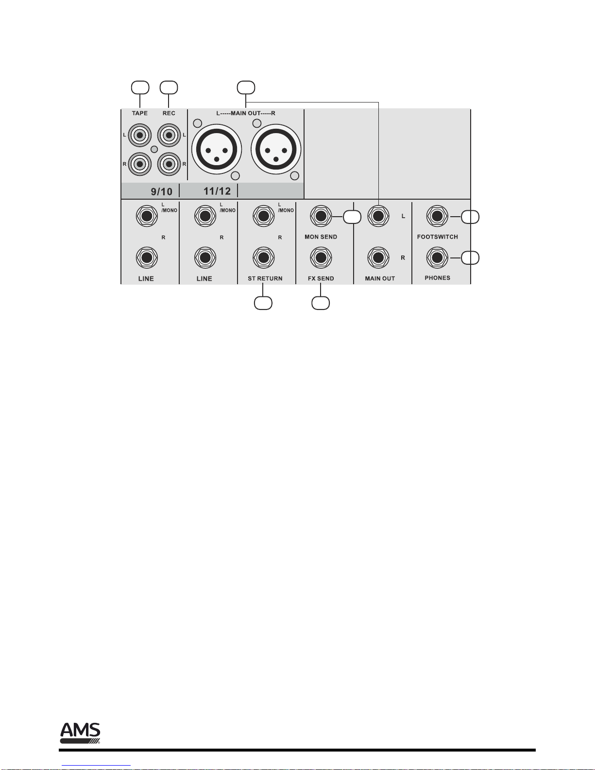
33. STEREO RETURN FADER
Use this fader to adjust the level of any audio coming into the stereo return inputs from external processor
or other equipment.
34. FX RETURN FADER
Use this fader to adjust the level of the stereo output from the internal FX processor being added to the
main mix.
35. MONITOR FADER
This fader controls the overall level of the monitor send signal sent out to the stage monitors.
36. MAIN FADER
This fader controls the level of the main mix and affects the meters and main line-level outputs.
27
28
29
30 31
32
33 34 35 36
27. MP3 PLAYING SYSTEM
28. PHONES LEVEL
29. FX SEND
30. FX TO MON
31. USB LEVEL
32. TAPE LEVEL
AMX Series - 5 - User Manual / Manual de uso

39. XLR AND 1/4 JACK MAIN OUT
In this product, the final confirmed sound can be send to main amplifier through XLR & 1/4 jack.
37. TAPE
These stereo unbalanced RCA inputs are designed to work with semi-pro as well as pro player/recorders.
37 39
40 42
43
44
38
38. REC
These stereo unbalanced RCA outputs allow you to record the main stereo mix onto a tape deck, hard disk
recorder, automatic CD burner,computer,etc.
40. STEREO RETURN
This is where to connect the outputs of parallel effects devices.The circuits will handle stereo or mono,balanced
or unbalanced signals.
41. MON SEND
The monitor mix could be adjusted in level using the aux mon controls. These tap a portion of each channel’s
signal to provide a 1/4” TRS output here to feed external stage monitors.
42. FX SEND
This 1/4” TRS line-level output may be used to feed an external effects processor. The output from this jack
is an exact copy of what goes into the internal FX processor,
43. FX FOOTSWITCH
This 1/4” TRS connector is where to connect a footswitch. This will allow you to mute or un-mute the internal
effects.
44. PHONES
This 1/4” TRS stereo jack will drive any standard headphone to very loud levels.
C. MIXER OUTPUT SECTION
41
AMX Series - 6 - User Manual / Manual de uso

D. POWER SECTION
48. LINE IN
This is the input 3.5 jack, controlling the signal to the right stereo channel.
46. POWER SWITCH
Press the top of the rocker switch to turn on the mixer.
45. POWER CONNECTION
This is the AC power connector
47. USB PORT
The USB interface allows digital audio to transfer to and from a computer.
45 46 47 48
AMX Series - 7 - User Manual / Manual de uso

AMX Series - 8 - User Manual / Manual de uso

AMX Series - 9 - User Manual / Manual de uso

AMX Series - 10 - User Manual / Manual de uso

AUDIOMUSIC
Avda. El Saler, 6 - Pol. Ind. L´Alteró, 46460 - Silla (Valencia) Spain
Tel. +34 963 124 088 Fax + 34 963 219 645
www.audiomusic.es [email protected]
Table of contents
Other AMS Music Mixer manuals
Popular Music Mixer manuals by other brands

Yamaha
Yamaha PM 5000 Series owner's manual

American Audio
American Audio VMS5.0 User guide and reference manual

Behringer
Behringer Europower PMP6000 quick start guide

Lightronics
Lightronics TL4008 owner's manual

Yamaha
Yamaha MG8/2FX owner's manual

The Singing Machine
The Singing Machine SMB-543 instruction manual