Intellijel Mixup User manual
Mixup Manual
Mixup
Chainable Stereo Audio Utility Mixer
Manual Revision: 2017.12.07

Mixup Manual
Table of Contents
Table of Contents
Overview
Installation
Before Your Start
Installing Your Module
Front Panel
Controls
Inputs & Outputs
Back Panel
Architecture
Technical Specifications
Page 1

Mixup Manual
Overview
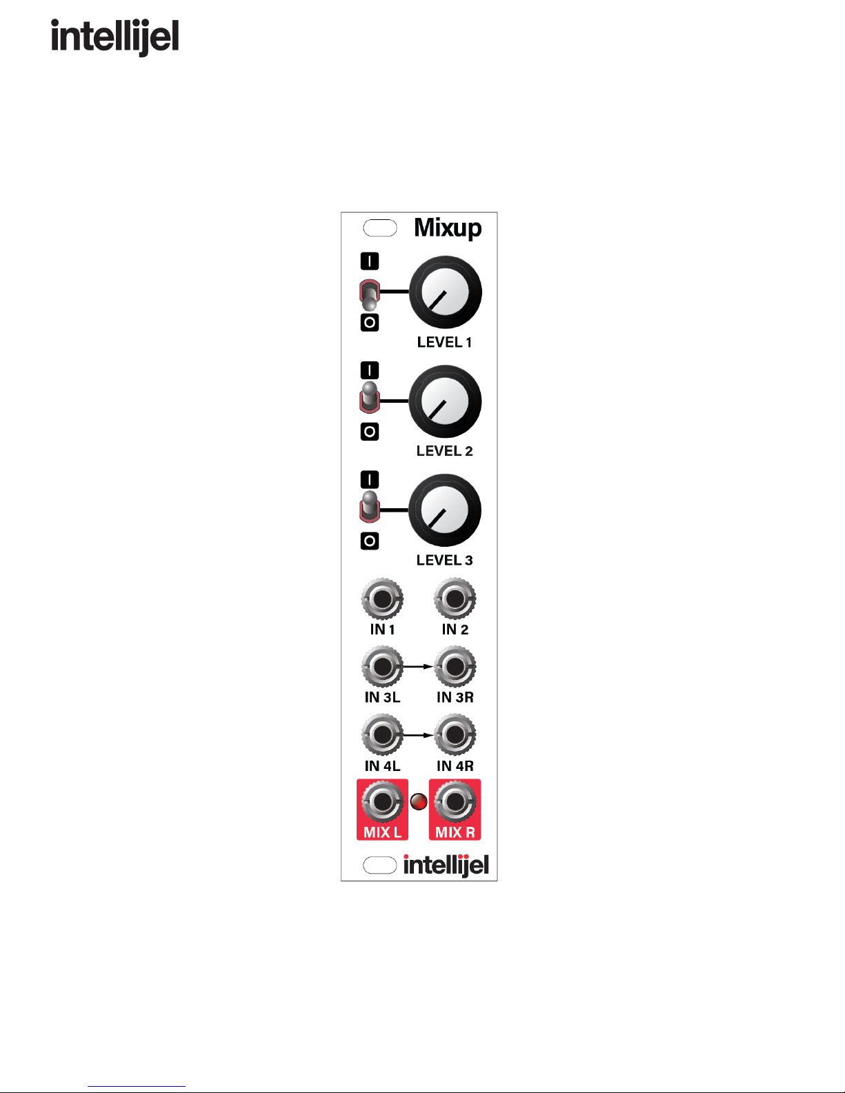
Mixup is a versatile, expandable audio mixer for eurorack format. It has six front panel
inputs and two outputs. Inputs 1 and 2 are single-channel mono inputs, each with its own
mute switch and level control; Input 3 is a dual-channel stereo input with a shared mute
and level control; and input 4 is an auxiliary unity-gain, non-mutable stereo input.
Using bus connectors on the back panel, you can chain multiple Mixups together in
series, giving you the ability to mix together even more inputs, or to create sub-mixes for
routing around larger systems.
Because Mixup is designed specifically for audio (and not for CV mixing), it uses
AC-coupled circuitry (which reduces the potential for ‘pops’ when muting and unmuting
audio), and it uses audio-grade, logarithmic attenuators for a smooth, even response
across the entire volume range.
Page 2

Mixup Manual
Installation
Intellijel Eurorack modules are designed to be used with a Eurorack-compatible case and power
supply.
Before Your Start
Before installing a new module in your case you must ensure your case’s power supply has
sufficient available capacity to power the module:
● Sum up the specified +12V current draw for all modules, including the new one. Do the
same for the -12 V and +5V current draw. The current draw will be specified in the
manufacturer's technical specifications for each module.
● Compare each of the sums to specifications for your case’s power supply.
● Only proceed with installation if none of the values exceeds the power supply’s
specifications. Otherwise you must remove modules to free up capacity or upgrade your
power supply.
You will also need to ensure you have enough free space (hp) as well as free power headers in
your case to fit the new module.
You can use a tool like ModularGrid to assist in your planning. Failure to adequately power your
modules may result in damage to your modules or power supply. If you are unsure, please
contact us before proceeding.
Installing Your Module
When installing or removing a module from your case always turn off the power to the case and
disconnect the power cable. Failure to do so may result in serious injury or equipment damage.
Ensure the 10-pin connector on the power cable is connected correctly to the module before
proceeding. The red stripe on the cable must line up with the -12V pins on the module’s power
connector. The pins are indicated with the label -12V, a white stripe next to the connector, the
words “red stripe”, or some combination of those indicators.
Page 3

Mixup Manual
Most modules will come with the cable already connected but it is good to double check the
orientation. Be aware that some modules may have headers that serve other purposes so
ensure the cable is connected to the right one.
The other end of the cable, with a 16-pin connector, connects to the power bus board of your
Eurorack case. Ensure the red stripe on the cable lines up with the -12V pins on the bus board.
On Intellijel power supplies the pins are labelled with the label “-12V” and a thick white stripe:
Page 4

Mixup Manual
If you are using another manufacturer’s power supply, check their documentation for
instructions.
Once connected, the cabling between a module and power supply should resemble the picture
below:
Before reconnecting power and turning on your modular system, double check that the ribbon
cable is fully seated on both ends and that all the pins are correctly aligned. If the pins are
misaligned in any direction or the ribbon is backwards you can cause damage to your module,
power supply, or other modules.
After you have confirmed all the connections, you can reconnect the power cable and turn on
your modular system. You should immediately check that all your modules have powered on
and are functioning correctly. If you notice any anomalies, turn your system off right away and
check your cabling again for mistakes.
Page 5
Mixup Manual
Front Panel
Controls
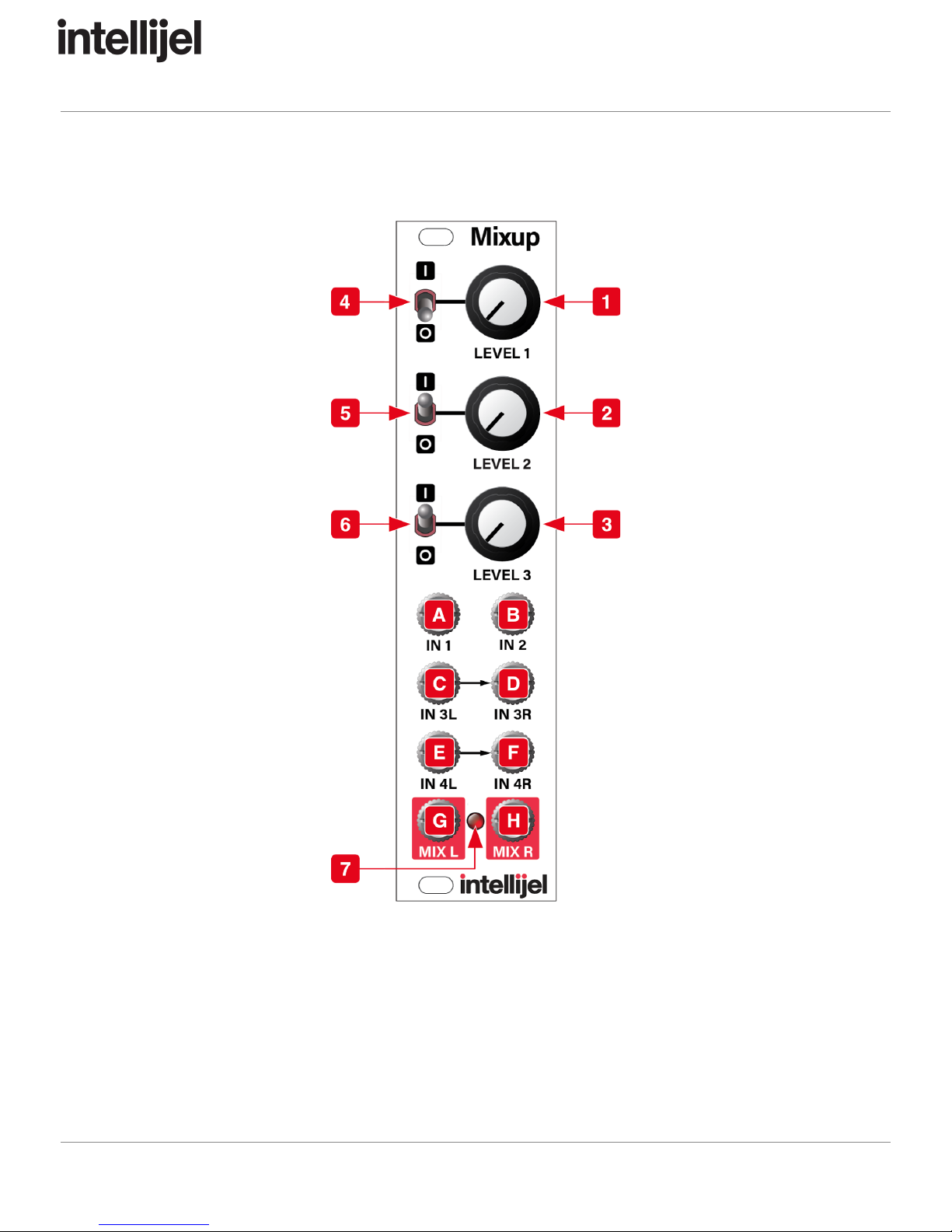
1. LEVEL 1 - This attenuator reduces the IN 1 mono audio level sent to both MIX outputs.
2. LEVEL 2 - This attenuator reduces the IN 2 mono audio level sent to both MIX outputs.
3. LEVEL 3 - This attenuator reduces the IN 3L and IN 3R stereo audio level sent to the
MIX outputs.
Page 6

Mixup Manual
4. MUTE 1 - In the down position, this switch mutes IN 1 — removing it from the MIX
outputs.
5. MUTE 2 - In the down position, this switch mutes IN 2 — removing it from the MIX
outputs.
6. MUTE 3 - In the down position, this switch mutes both IN 3L and IN 3R — removing
them from the MIX outputs.
7. CLIP LED - This LED lights when the sum of all the inputs (from the front panel jacks
plus the rear panel serial bus) causes either side of the stereo MIX output to clip.
Obviously, the more inputs you feed into Mixup (or the more Mixups you feed into each
other), the greater the potential to overdrive the Mix bus. So if the CLIP LED lights,
consider reducing the various LEVEL knobs to maintain a clean output (unless you want
distorted audio, of course).
Inputs & Outputs
A. IN 1 - Mono audio input 1. Mixup routes the audio from IN 1 to both the MIX L and MIX R
outputs. It can be muted with the MUTE 1 switch, and its audio level is determined by the
LEVEL 1 knob.
B. IN 2 - Mono audio input 2. Mixup routes the audio from IN 2 to both the MIX L and MIX R
outputs. It can be muted with the MUTE 2 switch, and its audio level is determined by the
LEVEL 2 knob.
C. IN 3L - This is the left side of stereo audio input 3. Mixup routes the audio from IN 3L to
the MIX L output. It can be muted (along with IN 3R) using the MUTE 3 switch, and its
audio level (along with IN 3R) is determined by the LEVEL 3 knob. If nothing is plugged
into IN 3R, then IN 3L acts like a mono input, and Mixup routes its signal to both the
MIX L and MIX R outputs.
D. IN 3R - This is the right side of stereo audio input 3. Mixup routes the audio from IN 3R
to the MIX R output. It can be muted (along with IN 3L) using the MUTE 3 switch, and its
audio level (also along with IN 3L) is determined by the LEVEL 3 knob. If you wish to
use input 3 for mono instead of stereo, simply plug a mono signal into the IN 3L jack,
and leave the IN 3R jack unconnected.
E. IN 4L - This is the left side of stereo audio input 4. Mixup routes audio directly from IN 4L
to the MIX L output, and has neither a mute switch nor a level knob. If nothing is plugged
into IN 4R, then IN 4L acts like a mono input — appearing at both the MIX L and MIX R
outputs.
F. IN 4R - This is the right side of stereo audio input 4. Mixup routes audio directly from
IN 4R to the MIX R output, and has neither a mute switch nor a level knob. If you wish to
Page 7

Mixup Manual
use input 4 for mono instead of stereo, simply plug a mono signal into the IN 4L jack,
and leave the IN 4R jack unconnected.
G. MIX L - This is the mixed audio output of all audio on Mixup’s left bus. This includes
audio from IN 1, IN 2, IN 3L, IN 4L, plus all left-channel audio from other Mixups you
might connected to its back panel CHAIN-IN connector.
H. MIX R - This is the mixed audio output of all audio on Mixup’s right bus. This includes
audio from IN 1, IN 2, IN 3R (or IN 3L if IN 3R is not connected), IN 4R (or IN 4L if IN 4R
is not connected), plus all right-channel audio from other Mixups you might connect to its
back panel CHAIN-IN connector.
Page 8

Mixup Manual
Back Panel
Each Mixup module features a pair of rear panel connectors, which enable you to serially
connect multiple Mixups to create a larger mixer with more inputs.
1. CHAIN OUT - This connector taps into the Left and Right MIX bus outputs. Use the
supplied link cable to connect the CHAIN OUT of one Mixup to the CHAIN IN connector
on another Mixup.
2. CHAIN IN - This connector adds another pair of inputs directly to the Left and Right MIX
bus. Use the supplied link cable to connect the CHAIN IN of one Mixup to the
CHAIN OUT connector on another Mixup. The CHAIN IN connector is essentially
another input much like “Input 4.”
NOTE
:
Never
use
the
3-wire
link
cable
to
connect
a
Mixup
module
to
an
Intellijel
Pedal I/O
module.
Although
both
modules
use
this
same
cable/connector
—
they
serve
different
purposes
and
carry
different
signals.
Page 9

Mixup Manual
Architecture
Page 10
Mixup Manual
Technical Specifications
Width
6 hp
Maximum Depth
29 mm
Current Draw
15 mA @ +12V
16 mA @ -12V
Page 11
Other manuals for Mixup
2
Table of contents
Other Intellijel Music Mixer manuals


Popular Music Mixer manuals by other brands


Behringer
Behringer FEEDBACK DESTROYER DSP1100 user manual

Abtus
Abtus MU-MIX31-A-06-ST manual

ALLEN & HEATH
ALLEN & HEATH Xone: S2 Technical manual

GAI-Tronics
GAI-Tronics ICP9000 Installation and service manual

Ibiza sound
Ibiza sound DJM160FX-BT user manual

G+M Elektronik
G+M Elektronik APS-3 2 Series manual


