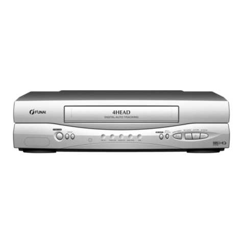
Marantz professional MV8300P User manual

MV8300P
Technical Manual
of RS-232 Protocol and Commands
D-VHS Digital VCR

<JLIP technical information>
Serial port setting
The serial port setting is these parameter in JLIP device.
(1) start bit : 1 bit
(2) stop bit : 1 bit
(3) parity bit : 1 bit
(4) type of parity bit : odd
(5) baud rate : 9600 bps
JLIP
p
rotocol does not have XON/XOFF se
q
uence.
If you have a opinion for the contents in this page : jlipmaster@skt.jvc-victor.co.jp
(Sorry for not accepting your personal technical question.)
Pa
g
e 1 of 1JLIP control s
y
stem develo
p
e
r
7/11/2003htt
p
://www.
j
vc-victor.co.
jp
/en
g
lish/tech/
j
li
p
/techinfo
_
f/techinfo
_
f1/serialset.html
MV8300P RS-232c Protocol Manual
D&M Professional Technical Support
www.marantzpro.com www.usa.denon.com/pro
630.741.0330 Extension 2

<JLIP technical information>
Data style of transmit and receive
JLIP device always transmit and receive 11 bytes data.
Command frame
It is a data sequence that contains control operation command from master controller like
PC to slave device like VCR.
It consists of the explanation below.
Header (2 bytes) : 0xFF + 0xFF
ID (1 byte) : one of number from 1 to 99 , or 127
Command body(7 bytes) : command operation code and parameters (*1)
Check sum (1 byte) : complement of the sum of other ten bytes of command
frame data (*2)
*1: refer to another document
*2: maximum bit is always 0 -- method of calculation is below.
Return frame
It is a data sequence that contains result of command operation from from slave device
like VCR to master controller like PC.
It consists of the explanation below.
Header (2 bytes) : 0xFC + 0xFF
ID (1 byte) : one of number from 1 to 99
Return body(7 bytes) : result or information of command operation (*3)
Check sum (1 byte) : complement of the sum of other ten bytes of command
frame data (*4)
*3: refer to another document
*4: maximum bit is always 0 -- method of calculation is below.
The first byte of 7 bytes-'Return body' is called 'command status', and it is for checking
command acceptance. (*3)
A maximum bit of every data except header data is always zero in JLIP.
Check sum data
A method of calculate check sum is like this.
r1 = (1st)+(2nd)+(3rd)+(4th)+(5th)+(6th)+(7th)+(8th)+(9th)+(10th)
Pa
g
e 1 of 2JLIP control s
y
stem develo
p
e
r
7/11/2003htt
p
://www.
j
vc-victor.co.
jp
/en
g
lish/tech/
j
li
p
/techinfo
_
f/techinfo
_
f1/datast
y
le.html
MV8300P RS-232c Protocol Manual

<JLIP technical information>
Basic method of device control
Command and response
JLIP device is transmitting and receiving 11 bytes data each other.
It is always that master device tarnsmit command frame at first. And the slave device
makes a response to it.
The slave device never transmit data without receiving command frame from master
device.
So, the master should wait the response from the slave device after transmitting command
frame.
Multiple device control
JLIP system is possible to connect many devices to only one serial port of master device.
Command frame has 'Command header' data for slave devide to recognize it.
And 'ID number' data shows which slave device the target is.
Each device that has each different ID number is possible to select and control one.
Broadcast command
ID number is normally set to one of number from 1 to 99.
But, if it is set to 127, then its command frame is for all slave device.
So, 127 is called broadcact ID number, and the command frame with it is called
broadcast command.
If broadcast command is transmitted, there is no response from any slave devices.
And after a decided time elapsed, the master device can transmit a new command frame.
If you have a opinion for the contents in this page : jlipmaster@skt.jvc-victor.co.jp
(Sorry for not accepting your personal technical question.)
Pa
g
e 1 of 1JLIP control s
y
stem develo
p
e
r
7/11/2003htt
p
://www.
j
vc-victor.co.
jp
/en
g
lish/tech/
j
li
p
/techinfo
_
f/techinfo
_
f1/te
j
un.html
MV8300P RS-232c Protocol Manual
D&M Professional Technical Support
www.marantzpro.com www.usa.denon.com/pro
630.741.0330 Extension 2

<JLIP technical information>
Command out
p
ut timin
g
Command output timing from master device is defined for stable
transmitting and receiving data.
(1) It is possible to transmit a next command frame after 80ms elapsed from
previous command frame output, if no response from the slave device.
It is also same timing after broadcast command outputs.(*1)
(2) Return frame from slave device is always coming within 55ms.
After transmitting command frame, a master device dedicates to receive return frame
from slave device for 55ms at a maximum.
But, if it received return frame of all 11 bytes data, it is possible to transmit next
command frame without waiting 80ms after the previous command frame transmitted. (*2)(*3)
(3) It starts transmitting return frame from slave device as soon as command frame
received.
A master device should start to receive data of return frame from slave device
immediately after transmitting commnad frame.
*1: It must be waited for 80ms after transmitting broadcast command.
*2: When some of multiple devices are connected to one serial port, master device
needs to wait for 80ms for stable receiving command by slave device.
You have better to program that waits 80ms after command transmitting every time
for multiple device control.
*3: When master device transmits command frame to some device, it needs to wait
for 3ms after receiving return frame.
If you have a opinion for the contents in this page : jlipmaster@skt.jvc-victor.co.jp
(Sorry for not accepting your personal technical question.)
Pa
g
e 1 of 1JLIP control s
y
stem develo
p
e
r
7/11/2003htt
p
://www.
j
vc-victor.co.
jp
/en
g
lish/tech/
j
li
p
/techinfo
_
f/techinfo
_
f1/timin
g
.html
MV8300P RS-232c Protocol Manual
D&M Professional Technical Support
www.marantzpro.com www.usa.denon.com/pro
630.741.0330 Extension 2
Table of contents


