manuals.online logo
Brands
  1. Home
  2. •
  3. Brands
  4. •
  5. Marantz
  6. •
  7. CD Player
  8. •
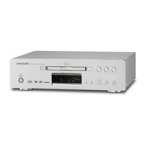
  9. Marantz CD-57 User manual

Marantz CD-57 User manual

Other manuals for CD-57

1

This manual suits for next models

20

Other Marantz CD Player manuals

Marantz SA8003 User manual

Marantz

Marantz SA8003 User manual

Marantz CD6000K User manual

Marantz

Marantz CD6000K User manual

Marantz CD5400 User manual

Marantz

Marantz CD5400 User manual

Marantz CD7300 User manual

Marantz

Marantz CD7300 User manual

Marantz UD7006 User manual

Marantz

Marantz UD7006 User manual

Marantz CD-95DR User manual

Marantz

Marantz CD-95DR User manual

Marantz HD-CD1 User manual

Marantz

Marantz HD-CD1 User manual

Marantz CD-5000 User manual

Marantz

Marantz CD-5000 User manual

Marantz CD6005 User manual

Marantz

Marantz CD6005 User manual

Marantz 74CD50 User manual

Marantz

Marantz 74CD50 User manual

Marantz SA8005 User manual

Marantz

Marantz SA8005 User manual

Marantz CD6005 User manual

Marantz

Marantz CD6005 User manual

Marantz CD5400 User manual

Marantz

Marantz CD5400 User manual

Marantz SA-10 User manual

Marantz

Marantz SA-10 User manual

Marantz ND8006 User manual

Marantz

Marantz ND8006 User manual

Marantz CD17MK3 User manual

Marantz

Marantz CD17MK3 User manual

Marantz CD5005 User manual

Marantz

Marantz CD5005 User manual

Marantz CD6004 User manual

Marantz

Marantz CD6004 User manual

Marantz PMD330 User manual

Marantz

Marantz PMD330 User manual

Marantz SA-11S2 User manual

Marantz

Marantz SA-11S2 User manual

Marantz CDR500 User manual

Marantz

Marantz CDR500 User manual

Marantz CD-43 User manual

Marantz

Marantz CD-43 User manual

Marantz CC4300N User manual

Marantz

Marantz CC4300N User manual

Marantz CD6005 User manual

Marantz

Marantz CD6005 User manual

Popular CD Player manuals by other brands

Arcam CD23 Handbook

Arcam

Arcam CD23 Handbook

Sanyo MCD-Z1F Service manual

Sanyo

Sanyo MCD-Z1F Service manual

JVC RC-ST3SL instructions

JVC

JVC RC-ST3SL instructions

Technics SL-P9066 operating instructions

Technics

Technics SL-P9066 operating instructions

Sony DVP-FX850 Service manual

Sony

Sony DVP-FX850 Service manual

Philips AZ1140 Instrukcja obs?ugi

Philips

Philips AZ1140 Instrukcja obs?ugi

Alpine 7909 owner's manual

Alpine

Alpine 7909 owner's manual

JVC CH-X350 instructions

JVC

JVC CH-X350 instructions

RCA RP-7923 instruction manual

RCA

RCA RP-7923 instruction manual

Pioneer DEH-P3550MP XM Operation manual

Pioneer

Pioneer DEH-P3550MP XM Operation manual

Philips Shockproof AX2102 brochure

Philips

Philips Shockproof AX2102 brochure

Philips CD582 user manual

Philips

Philips CD582 user manual

Philips AZ 6821 operating manual

Philips

Philips AZ 6821 operating manual

Lasonic MSU-2020 user manual

Lasonic

Lasonic MSU-2020 user manual

Denon DCD-1420 Service manual

Denon

Denon DCD-1420 Service manual

Panasonic SJ-MR100 operating instructions

Panasonic

Panasonic SJ-MR100 operating instructions

Onkyo DX-7210 instruction manual

Onkyo

Onkyo DX-7210 instruction manual

Cambridge Audio SONATA CD30 manual 

Cambridge Audio

Cambridge Audio SONATA CD30 manual 

manuals.online logo
manuals.online logoBrands
  • About & Mission
  • Contact us
  • Privacy Policy
  • Terms and Conditions

Copyright 2025 Manuals.Online. All Rights Reserved.

74
CD57/o1B/028/058
74
CD67/01B/028/05B/01G/026
A1BM2BA5B/12G
CD-67/67SE
ust,
rs,
en
Compact
disc
player
COMPACT
DIGITAL
AUDIO
TABLE
OF
CONTENTS
SECTION
PAGE
1,
TECHNICAL
SPECIFICATIONS
Cee
e
acer
a
nance
eee
e
neta
eens
eee ree
esse
nee
e
DOOD
POE
EE
EOE
Eee
ee
FER EEE
e
eee
teee
ene
reeorvesessonerane
1
5”
SEEN
ACOLIE:
1
nsarkbov
se
etihehssdac
sancti
yd
adten
i
uGasaeesanits
sateen
Sli
logue
iabiase!
2
3.
MICROPROCESSOR
AND
IC
DATA
Pee
e
cere emer
ae
te
eee eee
eee
e
ese
eee
see
S
EDO
H
OSES
TESS
HE
EHE
SEEDED
EEO
O
RES
OE
EEE
eee
rere
ebeeearesrer
3
4,
BLOCK
DIAGRAM
ee
eee
eee
eer
reer
ee
errr
rere
reer
ee
ee
errr
ee
ee
ee
eee
STOO
eee
Ce
eee
ee
eee
eee
eer
6
5.
SCHEMATIC
DIAGRAMS
AND
PARTS
LOCATIONS
(PATTERN
SIDE)
vrrsserssrserssrssessessessesseeseesesneeeaenny
7
6.
EXPLODED
VIEW
AND
PARTS
LIST
e---s-essessesssssssescessessecsscsssnscarecesseesusssssssscssessseessssssassanesnecasevences
17
EV
ECTRICAL:PARTSLIGT.
Sovisseientehielaniladaat
ia
naiecne
utiaanstaenatea
tamales
one
calaae,
20
Please
use
this
service
manual
with
referring
to
the
guide
(D.F.U.)
without
fall.
BORIS,
YP
RIRRAS
eSB
Be
ERO LER
eI
T<
KEL
mode!
CD-57
CD-67
CD-67SE
‘tissue:
1960
4822
72551124
186W&55090
MARANTZ
DESIGN
AND
SERVICE
Using
superior
design
and
selected
high
grade
components,
MARANTZ
company
has
created
the
ultimate
in
stereo
sound.
Only
original
MARANTZ
parts
can
insure
that
your
MARANTZ
product
will
continue
to
perform
to
the
specifications
for
which
it
is
famous.
Parts
for
your
MARANTZ
equipment
are
generally
available
to
our
National
Marantz
Subsidiary
or
Agent.
ORDERING
PARTS
:
Parts
can
be
ordered
either
by
mail
or
by
Fax..
In
both
cases,
the
correct
part
number
has
to
be
specified.
The
following
information
must
be
supplied
to
eliminate
delays
in
processing
your
order
:
1
.
Complete
address
2.
Complete
part
numbers
and
quantities
required
3.
Description
of
parts
4,
Model
number
for
which
part
is
required
5.
Way
of
shipment
6.
Signature
:
any
order
form
or
Fax.
must
be
signed,
otherwise
such
part
order
will
be
considered
as
null
and
void.
EUROPE
MARANTZ
EUROPE
B.V.
P.O.BOX
80002
BUILDING
SFF2
5600
JB
EINDHOVEN
THE
NETHERLANDS
PHONE
:
+31
-
40
-
2732241
FAX
:
+31
-
40
-
2735578
TRADING
MARANTZ
EUROPE
B,V,
P.O,BOX
80002
BUILDING
SFF2
5600
JB
EINDHOVEN
THE
NETHERLANDS
PHONE
:
+31
-
40
-
2732241
FAX
2
+31
-
40
-
2735578
CANADA
LENBROOK
INDUSTRIES
LIMITED
633
GRANITE
COURT,
PICKERING,
ONTARIO
L1W
3K1
USA
MARANTZ
AMERICA,
INC.
440
MEDINAH
ROAD
ROSELLE,
ILLINOIS
60172-
2330
USA
|
PHONE
:
708
-
307
-
3100
\
CANADA
PHONE
:
416-831-6333
:
708
-
307
-
2687
FAX
:
416-831-6936
PROFESSIONAL
CANADA
TC
ELECTRONICS
CANADA
LTD
540
FIRING
AVE.
BAIE
D'URFE,
QUEBEC
H9x
3T2
CANADA
PHONE
:
514
-
457
-
4044
FAX
1514
-
457
-
5524
rc
PROFESSIONAL
USA
|
SUPERSCOPE
TECHNOLOGIES,
INC.
|
MARANTZ
PROFESSIONAL
PRODUCTS
|
1000
CORPORATE
BLVD.,
SUITE
D
AURORA,
ILLINOIS
60504
USA
PHONE
:
708
-
820
-
4800
FAX
:
708
-
820
-
8103
AUSTRALIA
BRAZIL
HONG
KONG
MARANTZ
AUSTRALIA
MARANTZ
BRAZIL
FORWARD
INTERNATIONAL
CORP.LTD.
3
Figtree
Drive
Caixa
Postal
21462
15
TH
FLOOR,
REGENT
CENTRE,
88
QUEEN'S
ROAD,
CENTRAL,
H.
K,
PHONE
:
+852
521
-
0883
FAX
:
+852
521
-
7835
CEP
04698-970
Sao
Paulo,
SP,
BRAZIL
PHONE
:
0800
-
123123
(Discagem
Direta
Gratuita)
FAX
1
+55
11
534,
8988
Australia
Centre
Homebush,
NSW2140
AUSTRALIA
PHONE
:
+61
2
742
8311
FAX
1
+61
2
764
3074
MALAYSIA
WO
KEE
HONG
ELECTRONICS
SDN. BHD.
NO.
102
JALAN
SS
21/35,
DAMANSARA
UTAMA,
47400
PETALING
JAYA
SELANGOR
DARUL
EHSAN,
MALAYS
IA
PHONE
:
+60
3
-
7184666
FAX
:
+60
3
-
7173828
THAILAND
MRZ
STANDARD
CO,,
LTD,
746
-
750
WANGBURAPA
BANGKOK
10200
THAILAND
PHONE
:
+66
2222
9181
FAX
1
+66
2225
8871
TAIWAN
PAL
YUING
Co,,
LTD.
6
TH
FL
NO,
148
SUNG
KIANG
ROAD,
|
TAIPEI,
10429,
TAIWAN
R.O.C.
|
PHONE
:
+886
(2)
5221304
-
8
|
FAX
—
:
4886
(2)
5630415
SINGAPORE
FORWARD
MARKETING
(SINGAPORE)
PTE.
LTD.
29,
LENG
KEE
ROAD
SINGAPORE
|
59099,
PHONE
:
+65
475
-
4555
FAX
:
+65
475
-
8623
JAPAN
Technical
MARANTZ
JAPAN
INC.
35-1,
7-
chome,
Sagarniono
Sagamihara
-
shi,
Kanagawa
Japan
PHONE
:
+81
427
44
7950
FAX
:+81
427
48
0889
AAVSLy
RHA
*&
at
228
PHAR
SR
AB
ATR
TH
ABSA
SR
7
-
35-1
BRAB
+150
RRMRSER
MRM
1-11-9
SHOCK,
FIRE
HAZARD
SERVICE
TEST
:
CAUTION
:
After
servicing
this
appliance
and
prior
to
returning
to
customer,
measure
the
resistance
between
either
primary
AC
cord
connector
pins
(
with
unit
NOT
connected
to
AC
mains
and
its
Power
switch
ON
),
and
the
face
or
Front
Panel
of
product
and
controls
and
chassis
bottom.
Any
resistance
measurement
less
than
1
Megohms
should
cause
unit
to
be
repaired
or
corrected
before
AC
power
is
applied,
and
verified
before
it
is
return
to
the
user/customer.
Ref.
UL
Standard
NO.1492.
In
case
of
difficulties,
do
not
hesitate
to
contact
the
Technical
Department
at
above
mentioned
address.
960828KI
1.
TECHNICAL
SPECIFICATIONS
Audio
Characteristics
Channels’
i.
sescisescses
tendo
enasede
dacetensedn
osieas
deasdertes
Sampling
frequency
«0.0...
cessssesescssecsssetsessesseeeeseees
QUANTIZATION
-..seicsiseceececcsscvesssvaseesndacedsosutisesosstenseesess
D/A
CONVEISION
........cccccsecessesecessessressausesscecesseseesensees
Wow
&
flutter
ooo.
cceecessescessssssscessessseeseeeeee
Frequency
Characteristics
FrOQUENCY
ANGE
.......
sees
esectsceateeeessesscecsssaeeeeeens
Dynamic
range
......
eee
eeeseeeeeseseceecasessssesaceeeseenees
SIN
TAO:
s
sccssvissiedenssonseerevestsuaieaes
avmeassivsnsocdesiucteedet
Channel
separation
(1
KHZ)
..........csceesesessecsesereseees
VAD
(8
KAZ)
scesceveceeetesesctvesteves
cavcueevesdeavevedayssurantiesees
Analog
output
jack
Output
level...
eeecseceeecsscsesseeseeeseseasseeeeeeeee
Output
impedance
..........ceeeecsseeessssseseeescsaneees
Digital
output
PIN
JACK
vcsilsvcccscsatscesetcesvavcesacusadestecsodeiassescedasastisee
Optical
Output
v....00-.iSaascseevessertssvctadecsbeseoteradeciseetetrecs
Power
Supply
101,
/1
1
VOISION
Lasiiki.
seek
ncccctie
dette
eek
Be
ee
eecess
102, /05,
/12,
/15
V@rSion
........cccccccecsceesecescssesesensvsenens
POWEF
CONSUMPTION...
ee
eeeeeeeesseescesecseeseeesecseeeens
Cabinet,
etc.
Dimensions
Operating
temperatures
0.0...
ecssssseessseteerseeeeees
Operating
NUMIGIty
.....
ec
sceteeeeeteesenseneeseeseees
Accessories
Remote
control
unit
(RC-63CD)
oo...
eesseeeseeeeee
AA
(R6)
batteries
oo.
csecescetsescssessseeeteseeensens
Stereo
audio
cable
with
RCA
pins
............
cece
Specifications
subject
to
change
without
prior
notice.
CAUTION
VARO!
VARNING
ADVERSEL
DANGER
VORSICHT
CD-57
CD-67
CD-67SE
2
channels
44.1
kHz
16-bit
linear/channel
Cross-interleave
read
solomon
code
1-bit
linear/channel
Precision
of
quartz
GaAlAs
semiconductor
780
nm
5
Hz
—-
20
kHz
5
Hz
—-
20
kHz
5
Hz
—
20
kHz
>
96
dB
>
96
dB
>
96
dB
>
102
dB
>
104
dB
>
104
dB
>
100
dB
>
102
dB
>
102
dB
0.0025
%
0.0025
%
0.0025
%
2V
RMS
2V
RMS
2V
RMS
200
ohms
200
ohms
200
ohms
0.5
Vp-p/75
ohms
|
0.5
Vp-p/75
ohms}
0.5
Vp-p/75
ohms
—
-19
dBm
~19
dBm
115/230V
AC
50/60
Hz
230V
AC
50
Hz
|
11W
|
12W
12W
439
mm
439
mm
439
mm
86
mm
86
mm
88
mm
310
mm
|
310mm
|
310
mm
4.3
kg
4.3
kg
5.8
kg
+5
°C
~
+35
°C
5
%
~
90
%
(without
dew)
1 1
1
2 2
2
1 1
1
INVISIBLE
LASER
RADIATION
WHEN
OPEN.
AVOID
EXPOSURE
TO
BEAM.
AVATTAESSA
OLET
ALTTIINA
NAKYMATTOMALLE
LASER
SATTEILYLLE
ALA
KATSO
SATEESEN.
OSYNLIG
LASERSTRALNING
NAR
DENNA
DEL
AR
OPPNAD
BETRAKTA
&J
STRALEN.
USYNLIG
LASERSTRALING
VED
ABNING.
UNDGA
UNSAETTELSE
FOR
STRALING.
INVISIBLE
LASER
RADIATION
WHEN
OPEN.
AVOID
DIRECT
EXPOSURE
TO
BEAM.
UNSICHTBARE
LASERSTRAHLUNG
WENN
ABDECKUNG
GEOFFNET.
NICHT
DEM
STRAHL
AUSSETZEN.
CLASS
1
LASER
PRODUCT
KLASSE
1
LASER
PRODUKT
LH.T.
IEC
825
6.
A
fag
Ss
ae
.
POE
RE-EAOAU
e
(STOP].
[PLAY],
(NEXT].
[PREV]
keyD55
2
DLA
LeRL
CEREANS.~
»
HPO
-
Ger
P00)
TARE:
(FOCUS
OFF]
[SPINDLE
OFF)
(RADIAL
OFF]
(MUTE
ON]
e
[CUE]
keye#BTCALY
FOHEBHLET.
e
(REVIEW)
keys
#TCALY
FOARNBHLET.
e
(NEXT}
keye#TCE-FIANBALET.
C
SSP
1.
eer
APs
20%
TARE
>
(FOCUS
ON)
[SPINDLE
OFF]
(RADIAL
OFF}
(MUTE
ON]
e
(NEXT]
keye#OCE—-F2A\BALET.
e
[PREV]
keye#TCE—-FVN\BHLET.
RHR?
Gea
P
02)
tKRE
>
[FOCUS
ON)
[SPINDLE
ON]
[RADIAL
OFF]
(MUTE
ON]
e
(NEXT]
keya##OCE-FEINBHALET.
e
(PREVkeye#T¢CE—-FOUANBALET.
.
=-F3
GeR
P
03)
TARR
:
[FOCUS
ON)
(SPINDLE
ON]
(RADIAL
ON)
(MUTE
OFF}
e
[PREV]
keye#TCE—F2ABALET,
*
+-KRE—-FOLZTTORECMEO+—-DEM
TT.
1)
(STOP]
keye#OCFLUABRMNTLET.
2)
(PAUSE)
key@
#TCETVBSCN-Ysavern
LET.
Cd
67:
1
FOeRvt—-N-Vaves
3)
[PLAY]
key4#8O
CMR
O-ERE—-EDYD
tf
CEL
SUET.
RL,
REPRBRENKHICLS-BStRReEN
aS.
(Bl:
Err
10)
BORZBSAITL
TKK.
t-KRE—FORR
e
BRZDScC4v—-ERE—
EDRMRENET,
2.
1.
a
6.
SERVICE
MODE
How
to
enter
into
the
Service
Mode
*
Turn
the
power
on
while
pressing
at
least
2
of
[STOP],
[PLAY],
[NEXT],
[PREV]
keys.
.
Mode
0
(Display
P00)
Condition:
[FOCUS
OFF]
(SPINDLE
OFF]
[RADIAL
OFF]
[MUTE
ON]
®
The
Sled
moves
outside
when
pressing
[CUE]
key.
©
The
Sled
moves
inside
when
pressing
[REVIEW]
key.
©
The
function
moves
to
Mode
1
when
pressing
[NEXT]
key.
.
Mode
1
(Display
P01)
Condition:
[FOCUS
ON]
[SPINDLE
OFF]
[RADIAL
OFF]
[MUTE
ON]
©
The
function
moves
to
Mode
2
when
pressing
[NEXT]
key.
©
The
function
moves
to
Mode
0
when
pressing
[PREV]
key.
.
Mode
2
(Dispiay
P02)
Condition:
[FOCUS
ON]
[SPINDLE
ON]
[RADIAL
OFF]
[MUTE
ON]
©
The
function
moves
to
Mode
3
when
pressing
[NEXT]
key.
©
The
function
moves
to
Mode
0
when
pressing
[PREV]
key.
Mode
3
(Display
P03)
Condition:
[FOCUS
ON]
[SPINDLE
ON]
[RADIAL
ON]
[MUTE
OFF]
®
The
function
moves
to
Mode
2
when
pressing
[PREV]
key.
*
The
following
key
operation
can
be
available
at
all
of
the
conditions
of
the
service
mode.
1)
All
of
FL
display
light
by
pressing
[STOP]
key.
2)
Model
Number
and
Version
Nbr
of
the
u-processor
are
displayed
by
pressing
[PAUSE]
key.
Cd
67
:
10
|
-Processor
Version
Nbr.
3)
The
same
as
Normal
operation
(except
Service
mode)
is
performed
by
pressing
[PLAY]
key.
However
if
some
default
is
detected,
an
error
code
is
displayed.
(For
example:
Err
10)
The
content
for
each
error
code
is
shown
below.
[—EnorGode
|
Eror
Err
02
FOCUS
Error
Err
07
SUB
CODE
Error
Err
08
T.
O.
C
Error
Err
09
DECODER
Error
Err
10
RADIAL
Error
SLED
Error
SPINDLE
Error
SEARCH
Error
DOOR
Error
TRAY
Error
KEY
INPUT
Error
Err
11,
12
Err
13
Err
16
~
20
Err
30
Err
31
Err
32
~
47
Cancelling
the
Service
Mode
®
The
Service
Mode
is
cancelled
by
turning
the
power
off.
3.
MICROPROCESSOR
AND
IC
DATA
MN187164
(MICROPROCESSOR)
e)
CONANHAAWN
=
P26
P25
DATA
P24
CLOCK
P23
RAB
P22
SILD
P21
SCEDGESW
P20
P15
RCSIN
P14
TRAYSW
P13
P12
RC5OUT
Pit
MLEN
P10
ASTN
RST
POS
TRAYMOTOR
P04
POS
Po2
Pot
POO
SYNC
cM
P47
P46
P45
Pin
Nbr
Pin
Name
6
|
xO
7_|
P27
8
|
P26
9
|
P25
DATA
|
10
|
P24
CLOCK
P23
RAB
P22
SILD
P21
SLEDGESW
14
|
P20
P15
RCSIN
|_16
|
p14
TRAYSW
17
|
P13
O
|
49
|
Li
|
18
|
P12
RCSOUT
O
|
RC-5
code
Output
|
50
|
P65
(SEG13)
Lo
|
19
|
P11
MLEN
O
|
M5872
MLEN
(latch)
P64
(SEG12)
ho
|
20
|
P10
RSTN
O
|
SM5872
RSTN
(reset)
|
s2|
esses)
ia
|
3
0
22
|
POS
TRAYMOTOR
Oo
|
TrayMotor
P61
(SEG)
23
|
Po4
o
P60
(SEGB)
|
s6|
Psvisea7)
|
P56
(SEG6)
E
|
58
Pss
(secs)
0
27
|
POO
|_|
Not
Used
|
59|
P54
(SEGA)
)
28
|
SYNC
0
|
Not
Used
|
60|
Psaiseas)
fa
|
P52
(SEG2)
e)
30
|
P47
|_|
Key
Input,
KEY
8
fe)
Key
Input,
KEY
7
50
(SEGO)
oO
64
VPP
63
P50
(SEGO)
62
P51
(SEG1)
61
PS2
(SEG2)
60
P53
(SEG3)
59
P54
(SEG4)
58
P55
(SEGS5)
s7
P56
(SEG6)
56
P57
(SEG7)
55
P60
(SEG)
54
P61
(SEG9)
53
P62
(SEG10)
52
P63
(SEG11)
51
P64
(SEG12)
50
P65
(SEG13)
P66
(MSEL1)
P67
(MSELO)
P70
(KILL
IR)
P71
(DGT8)
P80
(DGT7)
P81
(DGT6)
Pa2
(DGTS)
Pas
(DGT4)
P84
(DGT3)
P85
(DGT2)
P86
(DGT1)
P87
(DGTO)
P40
P41
P42
P43
P44
-
Power
Supply
+5V
O
|
Clock
out
(8.0MHz)
I
Clock
in
(8.0MHz)
O
|
Not
Used
O
|
SAA7372
RESET
Jo|
Notuses
Data
Bus
Data,
SIDA
SAA7372
RAB
0
|
SAA7372
SILD
(latch)
|
Sledge
SW,
SLSW
O
|
Not
Used
|
RC-5
code
Input
Tray
In/Out
SW,
TRSW
vO
Oo
0
Key
Input,
KEY
6
uU
Pin
Nbr
Pin
Name
P
P
38
|
P87
(DGTO)
41
|
P84
(DGT3)
42
43
jperocte,
fo
|
jPeooct7
fo
|
P71
(DGT8)
=
P70
KILL
IR
P67
MSELO
P66
MSEL1
P44
P42
41
wo
>
Oo
i
oO
(eo)
46
47
jes}
pes
Lt
|
eyipukeys
|
34
35
Key
Input,
KEY
2
Key
input,
KEY
1
FL
Digit
Data,
G9
FL
Digit
Data,
G8
FL
Digit
Data,
G7
FL
Digit
Data,
G6
FL
Digit
Data,
G5
FL
Digit
Data,
G4
L
Digit
Data,
G3
L
Digit
Data,
G2
FL
Digit
Data,
G1
ill
IR,
N.C.
Model
Select
SW
0
Model
Select
SW
1
FL
Segment
Data,
P1
L
Segment
Data,
P2
n
na
n
L
Segment
Data,
P3
FL
Segment
Data,
P4
FL
Segment
Data,
P5
alee
Vpp
FL
Segment
Data,
P6
FL
Segment
Data,
P7
FL
Segment
Data,
P8
FL
Segment
Data,
P9
FL
Segment
Data,
P10
FL
Segment
Data,
P11
FL
Segment
Data,
P12
FL
Segment
Data,
P1
|
FL
Segment
Data,
F
Power
Supply
-2°
SAA7372GP
(DIGITAL
DECODING
IC
WITH
RAM)
[ewisoc]
PN
|
SSSSCSCSCSCSC«t
SCRIPTION
7
jor
|
unipolar
current
input
(central
diode
signal
input)
[oz
unipolar
current
Input
(central
diode
signal Input)
jos
|
unipolar
current
input
(central
diode
signal
input)
raterence
Input
tor
ADC
[os
7
unipolar
current
input
(central
diode
signal
Input)
fAt
unipolar
current
Input
(satellite
diode
signa!
input)
[R20
unipolar
current
input
(satelite
diode
signal
input)
(REFT
current
reference
tor
calibration
ADC
reference
output
from
ADC
analogue
supply”
selects
whether
intemal
clock
muttipfier
PLL
|s
used
current
feedback
from
data
slicer
comparator
signal
input
analogue
supply”
comparator
common
mode
input
reterence
current
pin
(nominally
Vop/2)
<5
<
<j
<
g
AR
;
ag
analogue
supply”
TESTt
tast
control
input;
this
pin
should
be
tied
LOW
[CRIN
|
crystal/resonator
input
crystaV/resonator
output
a
test
control
Input;
this
pin
should
be
tied
LOW
16.9344
MHz
system
clock
output
11.2896
MHz
clock
output
FRA
radial
actuator
output
[FO
|
focus
actuator
output
se
sedge
convo
oi
Tests
|
test
control
input;
this
pin
should
be
tied
LOW
<igital
supply
periphery”
[DORM
|
bi-phase
mark
output
(extemaily
butfered)
(tri-state)
rMoTo!
[|
=
33s
motor
out
1
-
versatile
(in-state)
pMOTO2
|
=
34
~—_|
motor
out
2
-
versatile
(tri-state)
psesy_
|
__35_|
subcode
byte
sync
(in-state)
fSFSY__|___96
|
subcode
frame
sync
(irtate
PACK
[37
[subcode
clock
Input
SUB
|
_
38
~—_[
Pto
W
subcode
bits
(tri-state)
Vas?
|
___
99
___|
tal
suppty
fs
|
__40___|
versatile
opt
pin
[va
[4
[versa
octpat
pin
[va
|
__42
|
versal
output
pin
(open drain
KILL
|
__43_—_[
kill
output
-
programmable
(open
drain)
|
44st
general
purpose
DAC
output
(Ir-state)
DATA
|
=
45_——_—*[
serial
data
output
(in-state)
word
clock
output
(ui-state)
47
digital
supply
periphery*
sertal
dit
clock
output
(tri-state)
Ggital
supply”
CU
ED
|
[SOA
|_51__[nPinerace
cata
VO
tne
(open
dm
ouma)
C=
Sct
[2
uPitertaca
cocking
CSC~‘“~*~C*S
Ra
|
_53__[
uP
tartace
RIW
and
oad
cori
ine
(Gecoderpan)
SiS
[_S4___—*|
uP
intertace
PW
andioad
corteline
(servopa)
i
[we
[88
[Noconnecton
SS
CSCSCS~CS
West
|
88
_—*(otaleupy
SSCS
RESET
[87
[power-on
mesatinp(eciveion)
SS
SSSCSC~*Y
STATUS
[58
|
request
ine/stans
register
put
open
drain)
C=
Vootc
[89
—«(Sghatsupplyeore”
SS
SSC~CS
[C2rAic
|
60
recaton
of
comecion
fale open
dra)
CS
[org
[61
[earection
fag
ouput
open
drain)
CSC*d
wi
versatioingtph
SO
SCSC~C~CSCSSCS
[ve
[6
[versatioinptp
SSCS
DON
|
__&
__[asercrive
on
outpatfopen
drain)
SCSC~*
°
Note:
All
supply
pins
must
be
connected
to
the
same
extemal
power
supply
voltage.
<lal
<=
g
8135
<
r
SM5872BS
(DIGITAL
FILTER
AND
D/A
CONVERTER)
XTO
<=
XTi
18bits,
fs
XVsg
—
Voo
CKSL
—
AVpp4
fs
CKO
—+r
RO
Two-times
interpolator
(45-tap
FIR)
MUTEO
——
AVsse
2fs
beh
Two-times
interpolator
(9-tap
FIR
ight-times
oversampling
MUTE!
—»
RON
re
aia
)
digital
filter
MCOM
——
AVpps
=
4fs
Two-times
interpolator
(5-tap
FIR)
LRCI
——
AVppe2
8fs
BCKI
—»
LON
Sample
and
hold
DI
—
AVssi
a2ts
MDT/FSEL1
—.,
LO
Zero-shift
noise
shaper
MCK/FSEL2
——
AVpo1
32fs
Se
UECO)
MLEN/DEEM
DVpp
Pulsewidth
modulator
RSTN
——
DVss
Quasi-symmetrical
PWM
outputs
Arithmetic
operation
Pin
Name
VO
Crystal
oscillator
output
“a
his
pin
should
be
tied
HIGH
for
normal
operation.
Internal
pull-up
resistor
Clock
output
(384fs)
UTEO
Mute
detect
output
UTEI
COM
RCI
CKI
Mute
input.
Internal
pull-resistor
Interface
mode
select
input.
Internal
pull-up
resistor
:
H
=
Interface
mode
L
=
Local
Data
sample
rate
clock
input.
Internal
pull-up
resistor
:
H
=
L
ch
L=Rch
ioe]
it
clock
input.
Internal
pull-up
resistor
erial
data
input.
Internal
pull-up
resistor
MDT/FSEL1
CK/FSEL2
LEN/DEEM
STN
Vss
Voo
Voor
Microprocessor
interface
data
input
(and
local
mode
frequency
select
input).
Internal
pull-up
resistor
Microprocessor
interface
clock
input
(and
local
mode
frequency
select
input).
Internal
pull-up
resistor
=
2/9
|9
|D
Dir
jz
lz
lz
IQ
/0
|x |x
Aixn|j<
{a
O
|@ |8
|O
@)
Microprocessor
interface
latch
enable
input
(and
local
mode
deemphasis
control
input).
Internal
pull-up
resistor
Reset
input.
Internal
pull-up
resistor
ND
(Digital)
‘ower
supply
(Digital)
N“N
a
vu
Power
supply
1
(Analogue)
c
eft-channel
positive
PWM
output
ND
1
(Analogue)
Left-channel
negative
PWM
output
Vss1
ao
jJ=|2
|=
4
Voz
Power
supply
2
(Analogue)
Vos
ower
supply
3
(Analogue)
ight-channel
negative
PWM
output
ND
2
(Analogue)
ight-channel
positive
PWM
output
|
=
>
mM
XS
>
>
lr
ic
cc
ais
<
6
|=
I|o
ts}
g
z
Vop4
Power
supply
4
(Analogue)
N
Power
supply
(X'TAL)
Crystal
oscillator
or
external
clock
input,
384fs
(16.9344
MHz)
a
[S|
4.
BLOCK
DIAGRAM
L.P.F
AN®
BUFFER
3B4ts
=F]
0102
SM5872BS
Q60!
SAA7372
CO
MECHANISM
COM-52.3
BSC
(0)
L.cH
bod
<
=}
o
2
a
(0)
R.CH
TRAY
MOTOR
ORIV
(M)
aeaynatod
INTVEXT
SW
RC-BUS
RCS
IN/OUT
BUS
—0)
ono
IR
1A3
ONTLAW
CB\-67/67SE
ONLY
ce
cee
eee
en
a
re
er
ee
ew
a
er
ees
Q108
1BA70734
CB-67/67SE
ONLY
HOAM
FS
x8
AND
BUAL
BAC
OVER
SAMPLING
AND
DISPLAY
BRIVER
2
fa)
$
cr
« 9
0
Wo
row
no
<c
o
$
a
2
Oo
2
=
JI”9,2
0
3
=
a
zu@aQ
IS
w
3,
rF¥o2Zz9
«
°
2
=a/6
—-EetE
OG
$4
9
aa
oo
We
ag
2B
a
te
a
wi
a2
a.
ee
an
SERVO
CONTROL.
KEY
SENS.
AND
BISPLAY
CONTROL
FOC
eRIVE
=
PROCSSOR
PLIFIRER
AND
HF
EQ
AM-
8.
OMHZ
(0
NM!87164
0107
TQA7073A
Q101
TBA1302T
Qyo3
POWER
ON
RESET
TURNTABLE
MOTOR
60--62-PI--PI4
KEYI--KEYA
VFI.
VF2
IR
o——_—_
POWER
INPUT
CONTROL
c
oO
fas
<
Zz
2
©
WW
c
ry
o
<
eK
2
Oo
>
+5V
+12V
-12V -24V
VOLTAGE
FALLING
POWER
SUPPLY
-24¥.
+/-10V
4SV
lw
SN@
1NO
A3X
GNY
AY
WSEG
KEYI--KEYa,
KEY
MATRIX
LE
VYO!
FTO
DISPLAY
9-MT-131GK
5.
SCHEMATIC
DIAGRAMS
AND
PARTS
LOCATIONS
(PATTERN
SIDE)
QH10,QH04,CH06,C1H52,C.N06
CH54.QH08,CH14,QH12QNO8
CQNO5,QHt1,QH13,QHO9,QH05
CNO7,0H03,QHS1,QH63,QH07
Q606
Qp01
Q605
QN92,QN91
QN25,QN24,QN20,QF02,QF52,0F51,QF61
P116
MAIN
PCB
Q811
QFO01
Q801,Q802
QN01,QN03,QN04
Q871,Q106
Q854,Q853
Q851,Q108,Q107
Q852
Q102
FOR
CONTINUED
CAUT
ION:
PROTECTION
AGAINST
FIRE
HAZARD.
REPL
Fool
Nikole
ATTENTION:
UNE
PROTECTION
AFIN
D”ASSURER
CONTRE
LES
RISQUES
PERMANENTE
D°
INCENDIE,
REMPLACER
|!
FUSIBLE
UNIQUEMENT
PAR
UN
|
DE
_WEWE
TYPE
FUSE.
PP16
(1/2)
-
POWER
AUDIO/DIGITAL
PCB
‘aaee
ade
aeaaa
yee
ieee
ee
ee
eee
eee
ESE
et
ileereeeeessye:
ag
RM
PCB
Pe
oe
TTT
12P
eee
—
”
[Besgoperbaggogoa
gases
gos
god go.
0
ra
p+
tet
ete
ee
io
8)
oh]
oy
;
ee ee
Glins
LcaL
aso
ase
ee
ee
10
an
I
y103
15
=
i
R
—2D
ot
on
xO
o
°
<
RFI7
10K
|
|
l
|
C126
Ke
47/1
6V
1.2
4
VFI
RYII
+5V
:
aaRA-
ar
4.7
©
7
)
«
Ray
aw
RAD
wll
an
RAt
+@
Ss
ror
:
Lroci
lol
ag
FOR
LO
0.2V,
:
‘
FO+
QFO1
(MN18716)
PIN
BC
VOLTAGE
5
FO+
1
(eae
HOF
=o
FZ
s.
ov
.
Ok
6
PIN
VOLT|PIN
VOLT
}PIN
voLT
|PIN
VOLT
AD
NO
4
cit
Oe
ov]
16
S.0v]31
0.0V
;
‘
04
is
5
=
—
a
T
:
©
17
32
0.0V
;
VETO
.
:
4
:
alLalaLaLaleaLalale
aLalela
@
>4)-<9-69-63-6}-69-€3-6)-63-6}-6)-69-4)-49
Ww
x
S
0
e
12
0.2V
o
O--<
18
ov}33
0.0V
|
>>
ReCUS
i
oe
19
5.0V134
0.0V
;
OSR!
:
Pw
A
;
mn
'
2
O33
a
OF
20
5,0V135
0.0V
eet
3
>>
RADIAL
WW
0.2V
=
O-
21
5.0v/36
0.0V
‘
:
’
|
oes
22
2.5V]37
0.0V
RFOI
GFO!
MNI87164
0302
:
38
-21.4V
o4V
40
-21.4V
o4V
7
4V
~4V
-4V|
~4V
23
24
25
26
27
28
23
0.0V
30
ea
DP
SLED
[o>
HF
(RF)
i>
DIG.
AUDIO
l=
ANA.
AUDIO
eee
eee
ee
eee
eee
comes
©
ees
ee
2
ee
©
en
©
ene
ee
©
eS
SE
©
ES
©
OE
©
oS
©
©
es
©
ones
©
oo
©
|
MAIN
P.C.B
PI164
°o
<
SLSW
4,7
iw
ie
P-P-D-O-G0-D-O-O-9-)-9-9--9---B
°
a
4
1S8254
CFOI
a
0.047
RFO2
e
J
1M
i
b
bri
Q
CF
02)
Or
o
l
|
a
le
47/180
I
1
yro1
RFI3
i
aaa
my
22K
me
L1210
|
panne
tray
sw[_]
[—]
Tray
sw
i=
R146
22k
RAB
0.0V
ain
R100
10K]
|
9108
TOA7073A
2.
VSSA2
trY+
A,
R107
c
(5)
R13
s
270«
|SELPLL
2.5V
1SLIGE]
=
=
Loiorma
aL]
s
R117
C108
c
4.7
174W
de
vSSA3,]
2.5V_TRY~
iss +5V +5A
Ss
C120
at
pees
BLS
sl
cl
a
Qa
>
HERI
LIREF
TESTI
47/16
RIOS
C125
cio
1k
th
470
2.5V
RIB
C109
yt5A
dp
7
'
Vay
i
tus
i
My
+58
0.047
C154
Rise
0.022
MOTO!
MCLK
.
_
.
Oo,
‘
|
T0A70734
,
<>
10ms/DIV
&
0.2ms/DIV
>
0.2ms/DIV
>»
0.1ps/DIV
if
<8»
20ns/DIV
QFO2
PS’
5
SERVICE
POSITION
0~2
SERVICE
POSITION
3
Se
ouaeae
Oi
abhe
5V
SERVICE
POSITION
0-2
SERVICE
POSITION
3
WN
"|
|
|
it
PHOTO
DIODES
SERVICE
POSITION
0
SERVICE
POSITION
1-3
|
|
CDM12.1
(TADI301)
ASYNCHRONOUS
pP
DEPENDENT
CONTINUE
DATE
ov
or
5V
5V
<>
tus/DIV
3
>
0.2us/DIV
<>
Sus/DIV
<>
S5ys/DIV
5V
<>
0.5ys/DIV
0.5ps/DIV
0.5ys/DIV
H
rm
m
;
EYEPATTERN
5V
5V
5
SRR
RRRRE
ov OV
_
WRK
OA
2.5V
Nissan
seaeevedeenaencdcneinl
ov
ov
ov
ov
LVR
MOVING
29
~—10-
13}
KEY8
wee
SS
sy,
Nn
o@
gy
ao
;
=~
NM
+
wr
an
a
SS8SESSSESESES
Fro
88
<P
PEETT
ET
TUNTTETT
PUTT
TT
ee
—
7
[1
909999950009959000
0
00bdbbbbbbSbbbbbSS]
[
PE+-+$-++-+-
4
=—san
a
Ppt
|
a
H
L_
||
[
1
VF2
+5V
A
KEY7 KEYS KEYS
KEY4
KEYS KEY2
KEY!
08M
OPTICAL
OUT
CIRCUIT
RTO
PT
ny
25
5.0V
26
5.0V
1
I
!
&
;
AZ
|
nS
!
|
c
!
I
PIN
VOLT
|
PIN
VOLT
H
|
ira}
«
16
5.0V131
0.0V
5
17,
—
|32
0.0V
|
CO-47/67SE
ONLY
na
18
5.0V/33
0.0V
wee
ee
Le!
re
19
S.0V
0.0V
C101
0.1
pto1
5460
JT02
a
20
5.0V
=
21
5.0V
22
2.8V
8
|
-
23
«5.0V
6-49-4946
6>-62-63-6)~6
63-6)
al?
|
comxian
;
=
26
5.0V
RC-5
1R-1N
(FROM
FRONT)
mobs
masad
es.
|
OF
U
—
i
RFO2
«
ols
|
27
«+5.0V
1M
5
a
ia
28
2.5V
gy
Sth
1
o
alnln
+sv
;
29
0.0V
|
1
ei
|
30_0.0V
Cpe
te
re
’
SFO!
|
ore)
EXT
6
emcees
5’
Seger
(oem
3
_|
RFOS
+5V
INT
IR
INT/EXT
+t
crs2
10725
ie
Fi
558
cs!
x
aaah
es
Ft
=
REO
SZL
Misc
&
=}en
2
6117
100
Sa
T
kit,
“ezb0.047
2
PMUT
yi
;
ie
1.2V_IREFT,
2.4
S
:
N23
F03
M
OF
04
TRY+
\
107
LVSSAz¢I
$8286
195254]
186256
HF
:
270k
|SELPLL
J
.
?
2.5V
1SLIGE]
2k
T.MOT+/=
aie
$198
Pore
POWN
POWN
A)
1/4W
.
2.5V_TRY~
ae
+5V +5A
i
a?
RNS
I
RN26
ay
ANZ
10K
47k 47k
c120
4
2.5V
NC
47/16
RIOS
c125
cio
aA
4792.5
2541048
N25
eae
(fr)
2saices
aii
SS
IY.
GR
A:
7
1/6W
Tien
.
2n
.
ron
isp
f
RMUT
LMUT
cis
Ae
RN27
RN28
46/16
<>
100K
100K
-12¥
-12V
5
>
0.2ms/DIV
®
0.2ms/DIV
”»
O.1ps/DIV
20ns/DIV
BV 5V
10X
8bits
SY
CONTINUE
DATE
ov
ov
>
tys/DIV
<>
susio1v
>
suso1v
sv
{>
osys01v
REED:
ey
i
EYEPATTERN
A
PHOTISRAS.
LELSSSRRCT.
UTHESENT
SRRSSORRAGAL
TKKEL
2.5V
ae
ae
NOTE
ON
SAFETY:
‘i
MXR
AAD
,
.
s
Ca
ov
ov
ov
TREE
{
Symbol
A
Fire
or
electrical
shock
hazard.
Only
original
parts
should
be
used
to
replace
any
part
marked
MOVING
with
symbol
A.
Any
other
component
substitution
(other
than
original
type),
may
increase
risk
of
fi
re
or
electrical
shock
hazard.
-10-
-11-