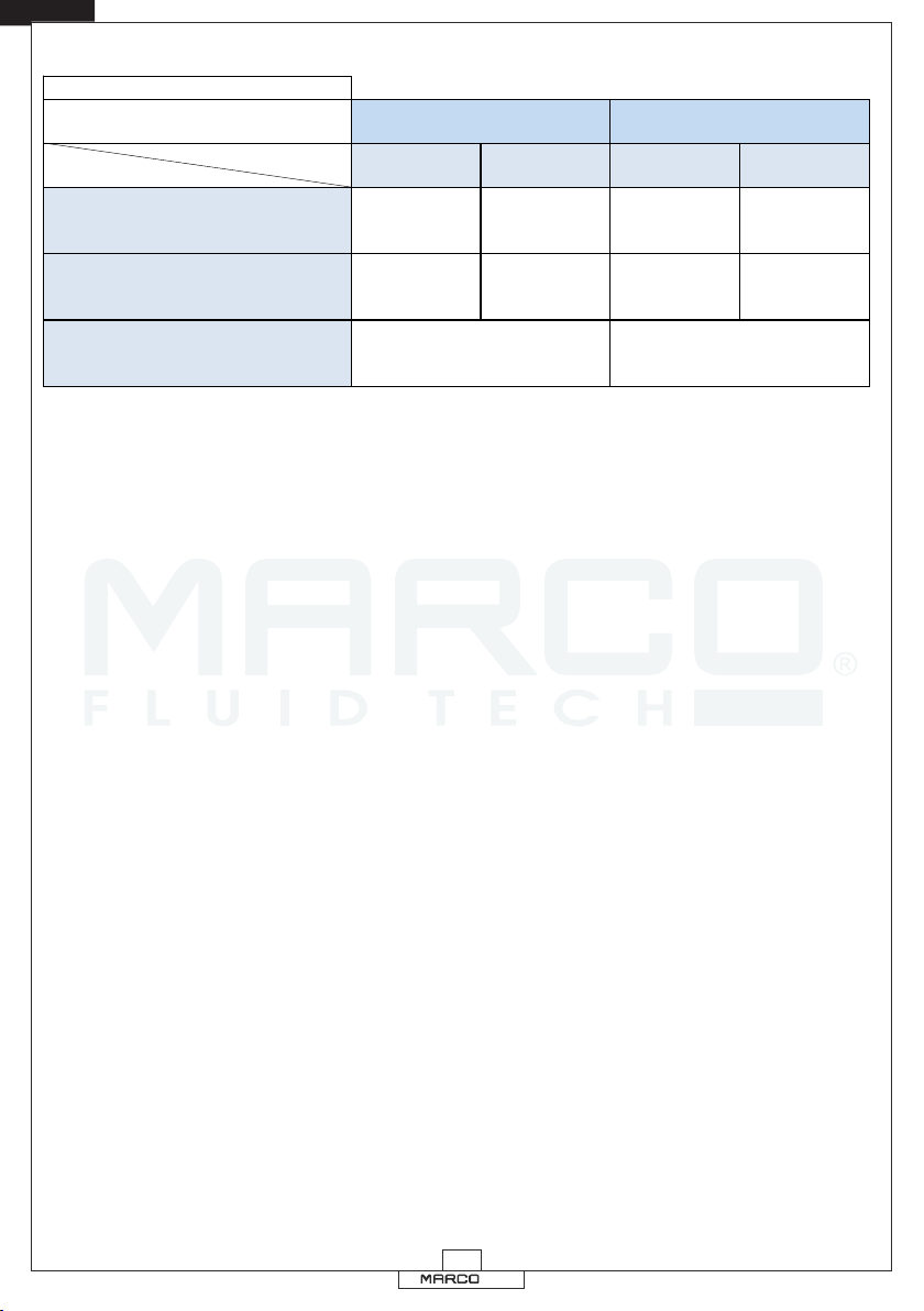
Marco SCS 165 20 415 User manual

© S.p.A.
AVVERTENZE D’USO
INSTRUCTIONS FOR USE
PANNELLO DI CONTROLLO
PER POMPE ELETTRONICHE
CONTROL PANEL
FOR ELECTRONIC PUMPS
Pannello di Controllo SCS
03/03/17 Rev.00
SCS Control Panel
165 20 415


© S.p.A.
Il pannello di controllo per pompe elettroniche permette di verificare a distanza il
funzionamento della pompa ed interagire con essa. È infatti possibile vedere
quando la pompa è accesa e se c'è ancora liquido da trasferire. E’ inoltre
possibile spegnere e riaccendere la pompa con semplice pressione di un tasto.
In caso di arresto per fine liquido o sovraccarico si può resettare l'avviso e far
ripartire il sistema senza dover togliere l'alimentazione. Inoltre i giri del motore
sono regolabili per evitare eventuali problemi di cavitazione e/o
surriscaldamento della pompa.
La luminosità dei LED del pannello è modificabile tra 8 differenti livelli: i LED si
accenderanno tutti insieme e successivamente si potrà incrementare o
decrementare l'intensità della luce.
Il pannello può essere montato ad in incasso in un foro circolare di diametro 70
mm oppure con montaggio esterno fissando con due viti la scatola quadrata in
dotazione.
Per il funzionamento è sufficiente il collegamento alla pompa con il cavo da 3m
in dotazione o con altro cavo telefonico a 4 fili e doppia terminazione RJ11/6.
Nella parte posteriore è presente una morsettiera che permette di replicare i
pulsanti e i LED presenti sul pannello su un circuito esterno: questo permette di
gestire in modo personalizzato le funzionalità in plancia o un dispositivo
progettato da terze parti.
PANNELLO DI CONTROLLO
I T
3

© S.p.A.
Tab.1 IT
TASTO TEMPO PRESSIONE BREVE PRESSIONE LUNGA (> 1,5 s)
ON/OFF Attiva / Disattiva Standby Nessuna Azione
RESET Reset Pompa e Pannello Nessuna Azione
ON/OFF+RESET Cambio Luminosità LED Nessuna Azione
ll pannello ha quattro tasti, con le seguenti funzioni:
Tasto «ON/OFF»: attiva o disattiva la modalità standby manuale
Tasto «RESET» : cancella eventuali segnalazioni di errore
La riduzione della velocità avviene premendo brevemente il tasto relativo alla
modalità attualmente in uso, fino a raggiungere la velocità desiderata:
l'impostazione viene quindi memorizzata e, selezionando la modalità (olio o
gasolio), la velocità sarà l'ultima impostata.
Premendo entrambi i tasti a lungo si attiva o disattiva la funzione di “FINE
LIQUIDO”.
La funzione di “FINE LIQUIDO” attiva fa spegnere la pompa dopo 90 secondi
con un assorbimento di corrente ridotto: permette di proteggerla da
funzionamento a secco ma potrebbe essere disattivata per liquidi con viscosità
molto bassa, in modalità olio, per evitare spegnimenti non necessari. In tal caso
sarà però necessario assicurare sempre presenza di liquido per evitare di
danneggiare il dispositivo.
Se viene inibito il “FINE LIQUIDO” il LED blu del sensore di pressione rimane
sempre spento (per segnalare la condizione straordinaria), che ci sia o meno il
liquido. Sul pannello il LED blu rimane lampeggiante poiché non viene più
effettuato l'aggiornamento dello stato. In questa condizione la responsabilità
di spegnimento della pompa è a carico dell'utente.
(segue)
Tasto «TARTARUGA»: attiva la modalità Olio
Tasto «LEPRE» : attiva la modalità Gasolio (velocità di Default)
I T
USO DEI TASTI
Premendo velocemente una volta entrambi i tasti nello stesso momento, si
entra nella modalità di impostazione della luminosità dei led. Premere il tasto
"reset" per aumentare la luminosità e il tasto "on/off" per diminuirla. Per
confermare la nuova impostazione, premere nuovamente entrambi i tasti.
4

© S.p.A.
Tab.2 IT
TASTO LED ACCESO LED LOW LED HIGH LED LOW LED HIGH
TASTO LEPRE Modalità Olio
Riduzione
velocità
Gasolio
Modalità Olio Velocità
Gasolio Default
TASTO TARTARUGA Riduzione
velocità Olio
Modalità
Gasolio
Velocità olio
Default
Modalità
Gasolio
TASTO LEPRE+TARTARUGA
PRESSIONE BREVE PRESSIONE LUNGA (> 1,5 s)
Nessuna azione Abilita / Disabilita
la funzione "Fine Liquido"
5
I T

© S.p.A.
Il pannello ha sei LED con le seguenti funzioni:
INDICAZIONI DEI LED
Tab.3 IT
LED
RUN
FAIL
LOW SPEED
HIGH SPEED
POWER
FLOW
FAIL+FLOW
FAIL+RUN
TUTTI I LED
LED FISSO ACCESO LED LAMPEGGIANTE
- Tensione di alimentazione errata
Pompa in funzione
La pompa è in standby automatico
La pompa riparte alla richiesta di
liquido dell'utente
Cortocircuito rilevato Sovraccarico rilevato
Modalità Olio attiva -
Modalità Gasolio attiva -
Circuito alimentato
Connessione rilevata
Circuito alimentato
Connessione non rilevata
Liquido rilevato Rilevamento Fine liquido
inibito
-Dopo 1' 30" senza liquido
la pompa si ferma
-
Sovraccarico
liquido troppo viscoso o
corpo estraneo fra gli ingranaggi
6
I T

© S.p.A.
INSTALLAZIONE
Si raccomanda l’uso secondo le disposizioni vigenti in termini di sicurezza e
le precauzioni di seguito riportate.
Si invita l’utente ad effettuare un’adeguata raccolta differenziata in modo da favorire
il riciclo dei materiali di cui è composto l’imballo; smaltimento con CER 15.01.01/02
SMALTIMENTO IMBALLO
CONTROLLI PRELIMINARI
Controllare che il non abbia subito danni durante il trasporto o lo dispositivo
Pulire con cura, rimuovendo eventuale polvere o materiale d’imballo residuo.
Verificare che l’alimentazione elettrica disponibile corrisponda a quella
richiesta dal dispositivo.
GARANZIA
SMALTIMENTO
N. on gettare il dispositivo dismesso tra i rifiuti domestici: esso deve essere
raccolto separatamente ed inviato ad una riutilizzazione ecologica.
1. Il periodo di garanzia è di 2 anni dalla data d'acquisto come risulta dalla
relativa fattura.
2. Nel caso la fattura non fosse disponibile il periodo di garanzia di 2 anni, sarà
calcolato dalla data di fabbricazione.
3. La garanzia decade e s'intende nulla in caso d'utilizzazione non corretta o nel caso
venissero ignorate le istruzioni contenute nel presente manuale.
4. La garanzia copre solamente i difetti di fabbricazione.
5. La garanzia non copre i costi connessi di installazione e smontaggio.
6. I costi di trasporto saranno rimborsabili solo nel caso in cui la garanzia sia stata
debitamente accettata da Marco S.p.A. e saranno limitati ai costi di spedizione tra
il magazzino di Marco S.p.A. e la sede del cliente.
7. Nessuna nota di credito o reso saranno effettuati prima di un test eseguito dal
Controllo di Qualità di Marco S.p.A. che dichiari difettoso il prodotto.
stoccaggio.
7
I T

© S.p.A.
CONTROL PANEL
The control panel for electronic pumps allows to remotely monitor the operation
of the pump and interact with it. It is in fact possible to see when the pump is On
and if there is still liquid to be transferred. Furthermore, you can turn Off and On
the pump with the simple push of a button.
In case of arrest due to end of liquid or overload, you can reset the alarm and
restart the system without having to turn off the power. Moreover, the speed of
the motor can be controlled in order to avoid problems like cavitation and/or
overheating of the pump.
The LED light intensity in the panel is editable choosing among 8 different levels:
every LED on the panel will turn on at the same time and afterwards the light
intensity may be increased or decreased
The panel can be mounted or recessed in a circular hole of diameter 70 mm, or
with external mounting by fixing the provided square box with two screws.
To operate simply connect the pump with the 3m cable supplied or another 4-
wire phone cord and double-ended RJ11 /6.
In the back there is a terminal block that allows you to replicate the buttons and
LEDs of the panel on an external circuit: this allows you to individually control the
features on the dashboard or a device designed by third parties.
8
ENG

© S.p.A.
Tab.1 EN
BUTTON TIME SHORT TIME PRESS LONG TIME PRESS (> 1,5 s)
ON/OFF Standby Enable / Disable No Action
RESET Pump and Panel Reset No Action
ON/OFF+RESET Brightness Change No Action
USING BUTTONS
«TURTLE» button: enables Oil mode.
«HARE» button: enables Diesel mode (Default Speed).
The panel has four buttons, with the following functions:
«ON/OFF» button: manual Standby Enable / Disable
«RESET» button: error Reset
To enter the brightness setting mode of the Leds quickly press once and
simultaneously both keys. Press the “reset” key to increase brightness and
press the “on/off” key to decrease it. To confirm the new setting press both keys
once again.
Speed reduction is obtained by briefly pressing the key of the mode currently in
use until the desired speed is reached: the setting is then saved and, by
selecting the mode (oil or diesel), the speed will be the last one saved.
A long press on both buttons toggles the “NO LIQUID” function.
This function turns the pump off after 90 seconds with low current draw: this
helps protect the pump from running dry, but it could be disabled with low
viscosity fluids, in oil mode, to prevent unwanted turn-offs. In this case, liquid
presence should be assured to prevent damage to the pump.
When the “NO LIQUID” function has been disabled, the blue LED on the
pressure sensor stays always OFF (to notify the particular condition), either in
the presence or absence of liquid in the pump. On the panel the blue led is
blinking, because its status is no longer updated. Under this condition the
responsibility for the pump-turn off lies entirely with the user.
(follows)
9
ENG

© S.p.A.
Tab.2 EN
BUTTON LED ON LED LOW LED HIGH LED LOW LED HIGH
HARE BUTTON Oil Mode
Diesel Speed
reduction Oil Mode Default
Diesel Speed
TURTLE BUTTON Oil speed
reduction Diesel Mode Default
Oil Speed Diesel Mode
HARE+TURTLE BUTTON No action "End Liquid" function
Enable / Disable
SHORT TIME PRESS LONG TIME PRESS (> 1,5 s)
10
ENG

© S.p.A.
The panel has six LEDs with the following functions:
ENG
LEDS INDICATIONS
Tab.3 EN
LEDs
RUN
FAIL
LOW SPEED
HIGH SPEED
POWER
FLOW
FAIL+FLOW
FAIL+RUN
ALL LEDs
- Wrong Voltage
Diesel Mode Enabled -
Powered circuit
Connected
Powered
Not connected
Liquid detected No liquid detection
Inhibited
-After 1' 30" without liquid
the pump stops
-
Overload
Liquid too viscous or
foreign body in the gears
Oil Mode Enabled -
SOLID LED BLINKING LED
Short Circuit detected Overload detected
Pump in function Automatic Pump Standby
Pump restarts upon user's request
11

© S.p.A.
INSTALLATION
PACKAGING ENVIRONMENTAL DISPOSAL
PRELIMINARY CHECKS
It is recommended that the use of the be according to normative safety product
standards and also as per the precautions listed below.
The user is invited to effect a proper waste separation, in order to facilitate the recycling
of the materials of which the packing is composed; disposal like CER 15.01.01/02
Check that there has been no damage to the during transportation or storage. product
Cleaned and removing possible dust or residual packaging material.
Verify that the available electrical power supply corresponds to the product
specification requirements.
WARRANTY
ENVIRONMENTAL DISPOSAL
Do not dispose of the device into household waste. Device that is non longer
usable must be collected separately and disposed of in an environmentally
2.
3.
4.
5.
6.
7.
1. The Warranty period is 2 years from date of purchase on production of the
appropriate sales invoice.
Should the original sales invoice not be available, then the 2 year warranty period
will be valid from production date.
The Warranty becomes null and void in the case of incorrect utilization or disregard
of the instructions contained herein.
The Warranty only covers original production defects.
The Warranty does not cover any related installation costs involved.
Transport costs are refundable only in the case where warranty has been duly
accepted by Marco Spa and they will be limited to the actual shipment costs
between Marco Spa warehouse and the client's delivery address.
No credit notes or replacement items will be issued prior to the receipt and proper
testing of any Marco goods that are deemed faulty.
ENG
correct manner.
12

© S.p.A.
PANNELLO DI CONTROLLO / CONTROL PANEL
ENG
I T
Presenza Tensione
Power On
Sovraccarico
Overload
Accensione
Power
Pompa Accesa
Pump On
Presenza di Liquido
Liquid Flow
Reset segnalazione
di errore
Error Reset
Bassa velocità
Low Speed
Alta velocità
High Speed
13

© S.p.A.
SCHEMA DI COLLEGAMENTO / CONNECTING LAYOUT
ENG
I T
RJ11
ALLA POMPA
TO THE PUMP
- GROUND
RUN LAMP (max 1A)
FAIL LAMP (max 1A)
WATER LAMP (max 1A)
RESET SW
POWER ON/OFF SW
+12/24
+12/24
+12/24
LAMPADE NON FORNITE
INTERRUTTORI NON FORNITI
LAMPS NOT SUPPLIED
SWITCHES NOT SUPPLIED
USB
14

© S.p.A.
SCHEMA DI FORATURA / HOLE SKETCH
Per il fissaggio del pannello di controllo con la sua scatola di contenimento,
forare il piano di appoggio seguendo la dima di foratura sottostante:
To fix the control panel with its box, drill the surface following the template
below:
Per il montaggio del pannello di controllo all’interno di una plancia strumenti,
forare la plancia seguendo la dima di foratura sottostante:
To fix the control panel on a dashboard, drill it following the template below:
ENG
I T
15

© S.p.A.
SCHEDA DI ASSEMBLAGGIO / EXPLODED VIEW
INGOMBRI / DIMENSIONS
Pos.
Q.tà
Descrizione
1
1
PANNELLO DI CONTROLLO
2
1
SCATOLA
3
1
GUARNIZIONE
4
4
VITE
5
1
PASSACAVO
Pos.
Q.ty
Description
1
CONTROL PANEL
1
BOX
1
GASKET
1
2
3
4
SCREW
1
GROMMET
4
5
ENG
I T
9 3/8"
80
3 1/8"
80 3 1/8"
42
1 5/8"
4 1/8"
46
1 3/4"
4
1
3
2
5
16

© S.p.A.
DICHIARAZIONE DI CONFORMITA’ C.E.
E.C. DECLARATION OF CONFORMITY
Confermiamo che il prodotto:
We confirm that the product:
è conforme alla Direttiva 2004/108/CE (ex.89/336/CE) relativa alla compatibilità elettromagnetica.
is in conformity with the Directive 2004/108/EC (ex.89/336/EC) relating to electromagnetic compatibility.
Questa dichiarazione è valida per tutti gli articoli prodotti secondo la documentazione tecnica che è parte di questa
dichiarazione. In caso di eventuali verifiche pertinenti alla Compatibilità Elettromagnetica sono state applicate le
seguenti normative:
This declaration is valid for all products which are produced in accordance with the technical documentation which
is a part of this declaration. For verification of conformity with regard to the Electromagnetic Compatibility the
following standards are applied:
EN 55014-1
Electromagnetic compatibility.
Requirements for household appliances,
electric tools, and similar apparatus.
Part 1: Emission.
Compatibilità elettromagnetica.
Requisiti per gli elettrodomestici,
gli utensili elettrici ed apparecchi similari.
Parte 1: Emissione.
Questa dichiarazione è rilasciata sotto la responsabilità esclusiva di:
This declaration is given under the sole responsibility of:
MARCO S.P.A.
Via Mameli 10 - 2501 Cas enedolo - Brescia - Italy 4 t
Tel. 030/2134.1 Fax 030/2134.300
EN 55014-2
Electromagnetic compatibility.
Requirements for household appliances,
electric tools, and similar apparatus.
Part 2: Immunity.
Compatibilità elettromagnetica.
Requisiti per gli elettrodomestici,
gli utensili elettrici ed apparecchi similari.
Parte 2: Immunità.
165 20 415 Pannello di Controllo SCS / SCS Control Panel
17

© S.p.A.
NOTE / NOTES
18


Questo documento e' proprieta' di Marco S.p.A la riproduzione e l'uso sono vietati.
Tutti i diritti sono riservati.
Per ulteriori informazioni vedere nostro sito internet - www.marco.it
Marco S.p.A Via Mameli 10 - 25014 Castenedolo (Brescia) – Italia
tel. +39 030 2134.1 / Fax +39 030 2134.300
Property of MARCO S.p.A reproduction prohibited. All rights reserved.
For further information visit our web site - www.marco.it
Marco S.p.A Via Mameli 10 - 25014 Castenedolo (Brescia) – Italy
tel. +39 030 2134.1 / Fax +39 030 2134.300
Table of contents
Languages: