For more information visit www.marcobeveragesystems.com
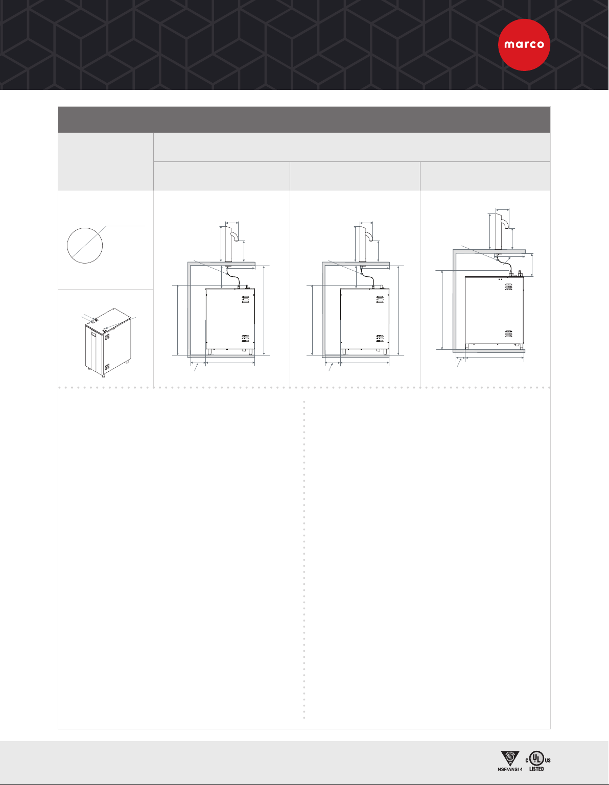
TUBULAR FONT WITH ECOBOILER UC4 & ECOSMART UC4, UC10 & UC45
COUNTER
CUT-OUT
TUBULAR FONT
1000584
ECOBOILER UC4 1000747US
ECOSMART UC4 1000750US
ECOSMART UC10
1000752US
ECOSMART UC45
1000754US
23”/585mm
15.5”/395mm
2”/50mm
11.9”/303mm
* Hosing should
be trimmed to
ensure continuous
drop from font
to boiler
4.5”/114mm
Ø 1.3”/32mm
Boiler Connections to Font
Water
Power Vent
2”/50mm*
2”/50mm
* Required for ventilation
if the machine is installed
in an enclosed cabinet.
>27.6”/700mm
min 5.1”/
130mm*
6.1”/
156mm
2”/50mm*
2”/
50mm
* Required for ventilation if
the machine is installed in
an enclosed cabinet.
23”/585mm
15.5”/395mm
2”/50mm
11.9”/303mm
* Hosing should
be trimmed
to ensure
continuous
drop from
font to boiler
4.5”/114mm
Ø 1.3”/32mm
Water Power
Vent
Boiler Connections to Font
6.1”/
156mm
6.3”/
161mm
min 5.1”
/130mm
* Required for ventilation
if the machine is installed
in an enclosed cabinet.
26.2”/667mm
19.4”/495mm
2”/50mm
11.9”
4.5”/114mm
6.3”/161mm
Ø 1.3”/32mm
Boiler Connections to Font
Dispense 1
Font #1 Connection
Vent
Dispense 2
2”/50mm*
2”/50mm
min 5.1”/130mm
6.1”/
156mm
* Hosing should
be trimmed
to ensure
continuous
drop from
font to boiler
2”/50mm*
2”/
50mm
* Required for ventilation if
the machine is installed in
an enclosed cabinet.
23”/585mm
>27.6”/700mm
15.5”/395mm
2”/50mm
11.9”/303mm
* Hosing should
be trimmed
to ensure
continuous
drop from
font to boiler
4.5”/114mm
Ø 1.3”/32mm
Water Power
Vent
Boiler Connections to Font
6.1”/
156mm
6.3”/
161mm
min 5.1”
/130mm
VENTILATION REQUIREMENTS
50mm/1.9” clearance required at each side and back of
machine if installed in an enclosed cabinet.
ELECTRICAL INSTALLATION PROCEDURE
When installing the machine, always observe the local
regulations and standards. The appliance is either supplied
with a NEMA L6-20P moulded power cord or a 515P power
cord. A suitable mains power supply socket should be
available within easy access of the appliance so that it can
be disconnected easily after install. The wires from the font
are terminated in a Mini Fit connector which will plug into
a similar Mini Fit connector mounted on the top lid of the
undercounter boiler.
PLUMBING INSTALLATION PROCEDURE
• Ensure that the equipment is installed according to
local plumbing & water regulations.
• Mains water pressure required (limits): 14.5 -145psi
(100 -1000kPa, 0.1 - 1MPa).
• Requires inline water filter within your water
specifications.
• The machine requires either a 3/8” compression,
or 3/8” John Guest water connection.
• Turn on the water to flush any impurities, dust etc
from the inlet hose and water pipe. Allow several litres
through. Especially for new installations. Connect the
hose to the inlet valve of the boiler. Make sure a sealing
washer is fitted.
• Turn on water and check for leaks.
• If the overflow vent is plumbed it must be plumbed with
a tundish device.
• This equipment must be installed with adequate
backflow protection to comply with all applicable
federal, state and local codes.
OPERATING BOILER FOR THE FIRST TIME
• Check that all installation procedures have been
carried out.
• Ensure water valve is on.
• Plug boiler appropriate electrical supply and press
power button on the front of the machine marked
‘Power’.
• The “power on” light will glow green and the machine will
fill to a safe level, above the elements, before heating.
• The “Ready/Status” light will cycle two red flashes while
the machine is filling to the safe level.
• After this amount of water has heated to about 95ºC
the boiler will draw more water in until the temperature
drops by 1 or 2 degrees. The boiler will then heat again.
This heat fill cycle continues until the boiler is full.
• Whilst the machine is above the safe level and filling,
the “Ready/Status” light will remain blank.
• The “Ready/Status” light will glow green when the
machine is both full and up to normal operating
temperature.
• The boiler is now ready for use.
• The font is simply activated by pressing the button
on the top of the font.
NOTE: Because the boiler is electronically controlled no
priming is necessary. The element cannot switch on until
a safe level of water is reached.
2”/50mm*
2”/
50mm
* Required for ventilation if
the machine is installed in
an enclosed cabinet.
23”/585mm
>27.6”/700mm
15.5”/395mm
2”/50mm
11.9”/303mm
* Hosing should
be trimmed
to ensure
continuous
drop from
font to boiler
4.5”/114mm
Ø 1.3”/32mm
Water Power
Vent
Boiler Connections to Font
6.1”/
156mm
6.3”/
161mm
min 5.1”
/130mm
TUBULAR FONT WITH ECOSMART/ECOBOILER
UNDERCOUNTER WATER BOILERS


