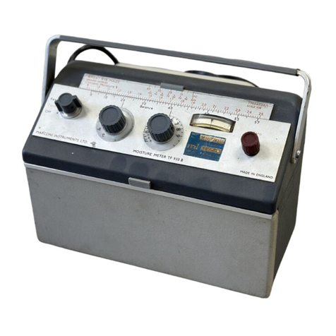
Marconi TF 933C User manual

Instruction Manual
No. EB 933C
for
Moisture Meter
TF 933C
1972
MARCONI INSTRUMENTS LIMITED
ST. ALBANS HERTFORDSHIREENGLAND
M.I. 2.5c
6/83/M
EB 933e
2g - 1/83

Contents
Chapter
1 GENERAL INFORMATION
1.1 Features
1.2 Datasummary
1.3 Accessories
Chapter
2 OPERATION
Installation
2.2 Controls and connections
2.3 Preparation of sample
2.4 Loading
the compression cell
2.5 Readingthe instrument
Avoiding
errors
Chapter
3 TECHNICAL DESCRIPTION
3.1 Circuit description
Chapter4 MAINTENANCE
4. 1
4. 2
4. 3
4. 4
4. 5
4. G
Introduction
Testing
Cleaning
Lubrication
Access andlayout...
Changingthe batteries
Chapter 5 (not assigned)
Chapter6 REPLACEABLE PARTS
Introductionand ordering
Chapter
7 CIRCUIT DIAGRAMS
Ci
rcuit notes
Fig. 7.1 Moisture
meter
8
8
9
9
11
13
16
17
17
18
18
20
21
23
24
9.

Chapter
1.1 FEATURES
General information
Themoisturemeter measures the "jointurecontentof a widerange
ofhygroscopic
materials, particularly thoseol' origin, in the field or laboratory.
Thetest cell which
is ofthecompressiontype stowedin the instrument
whennot in use. is suitable for granular, powde oc I ous
substances
and
for
specimensin the form of sheets or boards up to one inch in thickness. An important
function
ofthetest cell is theapplication
ofconsidetal'le pressure to the specimen
undertest in order to bringthe sampleto a unif01Mi and minimizepackingerrors.
Directreadingtemperature-correcting calculator neales can be slippedonto
theinstrument
for thecommoner
materials, such an ceteal grains, cigarette tobacco
andrice, while
a large numberofcalibrationcha are availablefor substances
ranging
from applerings to wool
socks.
The standard model is powered by two9 V into
t
mal(l
rv batteries.
Fig.1.1 Themoisturemeter withcompressioncell electrode and
calculatorscalefitted
933C (1)

1.2 DATA SUMMARY
RANGE:
ACCURACY:
SELF-CHECK FACILITY:
CALIBRATION:
SCALES:
Cereal grains and
agricultural seeds:
Flour and wheat:
Cigarette tobacco:
Moisturecontents from belowair-dry to near
satu ration.
Thebasic accuracy of the instrument is
10.5%,
m.c. , but variations duc to the nature
of the samples may reduce this to m.c.
Theaccuracy tends to fall at highmoistu
re
contents.
The instrumentmay be checkedagainst the
internal standard resistance of 1 MS)
at a
meter readingof40.
The calibrations, whichare made by comparison
with standard analytical procedures, are based
on ground samples wherever possible.
The standardapparatus includesthe Calibration
Datafor the cereal grains andagricultural seeds
9 to 25%
for wheat, rye andmaize; 8 to 24%
for barley andoats. Temperature -1 to 38
0c
(30to 100
O
F). The scales are based on oven
drying for four hours at 120oc (248O
F).
Tables are providedcovering agricultural seeds.
9 to 25%
for groundwheat; 10to for flour.
Temperature -I to 38 oc (30to 100
O
F); outside
the range 10to 30oc (50to 86O
F) there may be
a slight fall in accuracy. The scales are based
on oven drying for four hours at 120oc (24801").
Tablesare givenfor other mill stocks and
products.
8 to 20%
for 'cigarette rag' (equivalent to eut
whole
lean and9 to 21%
for cut lamina. Tern
perature 10to 30 oc (50 to 86 O
F). The sea
are based on oven drying for sixteen hours at
100 O c (212 O F).
93.'lC
(l)

Tick beans:
Rice:
Paper:
POWER SUPPLY:
n
DIMENSIONS:
WEIGHT:
1.3 ACCESSORIES
Accessories supplied
9 to 22.
10 to
on oven
(221 010.
10 Co
to 30
oven
•und01').
fifteen le is based
1101
inhed rice. "l'entpevaturc 10
(00 0F). Thescale is based on
tilleen hours at 105
oc (221OF).
4 to 1:1
1
},
pulp and
to 90 OF).
G
to 22%)
for chemical wood
e10to 32 oc (50
remperature
Suppletnentary information is
providedcovering roanytypes of wood
pulp,
paper and can. The scales are based ono
ovendrying to constant weightat 102to 105 c
(215.5
to
Internal
equivalent.
Height
7 3/4 in
(197mm)
01").
: twoPP3 9 V or
Width Depth
Il .'1/8
in 5 1/4 in
mm) (135
mm)
7 1b(3.I Kg)
nppro.ximately.
1. Compression Cell Electrode Assembly typo 'I'M '1
1IOA(complete with Clamp
TC 22429, Electrode TM4178A, Ring 22,120/2. Plunger TB 22425/1 and
3 ft Connecting Cable TM 4130A).
Note: The clamp is nowsuppliedwithout
tho rubber handgrip still
shownin the illustrations.
2. (he set of CalibrationData, 'CM
4473A/I see under Accessories available.
Aset of calibration data comprises a slip -onealeulator scale and a booklet,
card or sheet giving
supplementary
informationon substances covered by
the calculator scale and in some cases, allied substances.
3. One4 BAhexagonalwrench, Marconi type 22951-006; for carrying out
the standardization
test detailed in Sect, 4.2.
4. OneInstruction Manual No. EB 933C.
933C
(lc) 5

Content
Fig. 1.2 Themoisture meter showingaccessories
Accessories available
Standard Calibration Data:
Cereal grains andagricultural seeds
Flour and wheat
Cigarette tobacco
Tick beans
Polished rice and paddy
Paper
TM 4473A/1
TM 4473A/2
TM 4473A/3
TM 4473A/8
TM 4473A/9
TM 4473A/10
Special Calibration Data; can be supplied to order for a wide range of tuatetoala.

3. Smallgrinder; for grinding wholegrain etc.
4. Spare Standard Electrode "I'M
4178A; lor eojnpression cell
5. Large Electrode Unit TM 4178A/.'I
(contplete Ring TC and I
'lunger
TC 22433/2); ror use withcompression cell elect rode to large
samples. Theunit has a (lia
tneter ol' Inches and holds about 10 Ins.
6. Two9 Vbatteries; F.xidetype Ever Itea€lv
type PP3, Ray-o-Vac type
or Vidor type VT3 or equivalent.
933C (1)

Chapter Operation
2.1 INSTALLATION
NOTE Theperformance of this instrument maybe impaired by lengthy
exposureto a dampatmosphere. Dryingfor a short period in a
warmdry atmosphere will restore it to givenormal performance.
Ensure that the instrumentis switchedOFF before connectinganyleads and
onlyswitchedon when
actually takingmeasurements, hence prolonging
the life of
thebatteries.
2.2 CONTROLS AND CONNECTIONS
Balancecontrols
Theelectrical principle employedin the instrument is the variation of conductivity
of the specimenwithmoisture content. Conductivity
is measured by adjusting the
coarse andfineBALANCEcontrols to give a standard meter indication; the reading on
the controls is then easily converted into moisture content by reference to the scale on
the instrument or to a chart supplied with it.
In addition to the twoBALANCEcontrols there is a rotary switch marked OFF-
ZERO-READ
anda red ZEROknobfor standardizingthe instrument before takinga
measurement.
NOTE: If either of the BALANCE
controls becomes loose it must not be
secured without
first carrying out the standardization test detailed
in Sect. 4.2.
Electrode connections
•me compression cell electrode is normally stowed in the lower front compart—
of the moisture meter. Alsoinsidethis compartmelt are three sockets
labelled RED, GREEN
and BLACK. Connect the RED and BLACKsockets on the
893.w

compression cell electrode using the lead provided. Ensure that will' the
larger plugs goes to the main instrument and do not attempt to into
smaller sockets on the compression cell. Thore is no significance in
of the individual leads as there is no polarity to observe and the connectionn be
reversed withouteffect. The GREEN
socket ig not required for the
cell suppliedwiththis instrument and the other two sockets labelled CA
CHECK
are provided
for test purposesas described inChapter
Calculator scales
If a seale is availablefor the substance to be tested slide the scale into position -
see Fig. 1.1. If there is noscale availablethenselect the appropriate
calibration
data sheet.
The following
sections give the general method of operating the instrument.
Detailedprocedures that applyto particular materials are given in the calibration data
suppliedfor each group of substances.
2.3 PREPARATION OF SAMPLE
Granular or powdery
substances
Theinstrument may be used in two ways:
(a) wholegrain
(b) the flour or meal produced by coarse grinding
Tests onungroundgranular substances are strongly influenced by the surface
moisåare. Tests on wholegrains of wheat indicate substantially the bran moisture.
For this reason it is advisableto test the sample both wholeand ground, to give an
indicationof the moisture distribution as well as its average value.
The fineness of grinding is not important but the loss of moisture which may
occur, especiallywith
dampsamples, must be minimized. Therefore avoidvery
finegrinding. After grinding, flushout the grinder withthe sample to be tested
anddiscard the first ground sample.
Fibrous material
Ingeneral theprocedure is the same as for granular materials.
The cavity for the test cell should be approximately half filled with the specimen
tmtilpacked
tmiformly, pressing the specimendown
in muchthe same manner as
filling a pipe. After the test the compressed plug should be about 1.6 mm thick, or
3.2 mm for the large cell.
2.4 LOADING THE COMPRESSION
CELL
The following
description may appear complicatedbecause each detail is
mentioned
but the procedure willbe foundquite simple and convenient.
933C (1b)

(i) Unscrewthe clamp. Withdraw
the test cell. Take out the plunger,
(2) See that the insulating ring is well seated on the electrode with its open end
upua
rds. Tn
handling the electrode, hold by the edges. Donot handle the upper
surface as this maydepositmoisture on the insulatingsurface between the two
electrode rings.
(3) (a) For wholegrains put enoughinto the test cell to form a single layer.
(b) For groundsamples half fill the test cell withmeal. After the test the
compressed plugshouldbe about1.6 mm (or 3.2 mm for the larger test
cell). Ensure that the sample is lying uniformly in the bottomof the test
cell; a gentle shakewill ensure this in most cases.
(4) Insert the plungerandholdit down(toprevent the sample slipping to one side)
then slide the complete test cell intothe clamp.
(5) Screw the clamp down
until the twoparts of the cylindrical spring housing,
nummt.ed
on the end of the screw, become flush.
CAUTION The spring is compressed solid byabouta half turn of the screw
beyondstandard thrust at whichtests are made. The solid point
can easily be felt on the tommy-bar. DONOTATTEMPTto
tightenbeyond
this point as it is possible for a strong operator to
strain the clamp.
Fig.2.1 Compression
cell electrodeassembly
Takeelectrode (A)
Add ring (B)
Jlalf fill the cavity
then add plunger (C)
Screw the assembly downin
the clamp until flush at (D)
(A) (B) (C)
10

Sheets and boards (e.g. cardboard)
Thin
The ring andplunger of the test cell are not required for those for the
sheets should
be foldedto givea thickness of about0.25 mm,
large test cell.
Fig. 2.2 Use of compression
cell
with thin sheet materials
Place the electrode inpositionon the base of the clamp. Put the sheet to be
tested onthe electrode and screw downthe clamp until the two parts of the cylindrical
springhousing, mountedon the end of the screw, become flush.
2.5 READING THE INSTRUMENT
SetZERO
Slidethe calculator scale betweenthe central retaining clip andthe BALANCE
scale graduationsas shown
in Fig. 1.1. Movethe scale alonguntil the vertical index
line onthe central retaining clip is in alignmentwiththe ambient temperaluve on the
temperature scale. (SeeSect. 2.Gif the material under test is not at ambient temp-
erature.) Fig. 2.3 illustrates the sequence ofoperations.
SET ZERO
Switchto ZERO. The meter pointer will deflect.
Turn the red ZERO
knobuntil the pointer rests at the centre mark.
933C (la) 11

NOTE:The 'tens' dial (left-hand BALANCEknob)should not be on the 0 or
positionswhen
settingzero. As these are the most sensitive ranges,
traces of leakagedue to atmospheric humidityand effect of electro—
static inductionmaycause the readingto be a little unsteady. Switch
to anyrangeother than0or I to set zero.
Switch
position
ZERO
is the 'stand-by' position
duringa series ofmeasurements.
Read
Theaccuracyofthe instrumentmaybe checkedagainst the internal standard
resistance if required - see Sect. 4.2.
(1) Havingfilled the cell, switch to READ.
(2) Set the units dial (the right—hand
BALANCEknob) to approximately O.
(3) Rotate the tens dial (the left—hand
BALANCE
knob)until the pointer crosses the
centre line on the meter.
(4) Adjustthe unitsdial to bring the pointer to the line. If the reading is on the
ægative part of the dial movethe tens dial onestep counter—clockwise
(unless it is
already at 0)and rebalance. The negative section of the dial should never be used
if a reading can be obtainedon the positive section.
Thefigures appearing
againstthe dial indexmarks constitute the dial reading.
Exceptfor readingsabove
50, little is gained
by recording the figure more closely
than half a unit. For readings between50and 60the figure should be determined to
oæ tenth of a unit.
NOTE
:Withvery lowmoisture content (i.e. 0or 1 positions of the 'tens' dial)
the readingmaybe a little unsteadydueto electrostatic effects.
Convert to moisture
content
Sliding
scales
Transpose the readings obtained on the knobdials to the fixed black scale.
Read the actual moisture content on the sliding red scale opposite the point
on the fixed black scale,
Paper charts
If noscale is availablefor the substanceunder test, convert the dial reading
to moisture contentby means of the calibration data sheet.
NOTE: SwitchOFF whenmeasurements are completed in order to conserve
power.
12 9'3ac (la)

4 SLIDING RED SCALE SHOWS scm.r ro
MOISTURE CONTENT (120 y.) ROOM UMPERATURE )
GROUNO E
S40 30 20
Content Moisture too 90
9'2 16 22 23 2'
20 50
Batance
2
3 DIAL READING
(2248) 2OlAU6
TRANSFERED TO
FIXED BLACK SCALE
Fig.2.3 Sequence
of reading moisturecontent
2.6 AVOIDING ERRORS
Sampling
errors
If several samples are tested from a st-oeK
ol'tn:tterialthe readings generally
will varya little. Thesevariations are due to localditTerences
in the moisture
content of the bulk and not to inaccuracies in the instxutnent. To get a representative
readingit is therefore necessary to test enough
satnples to make sure a goodaverage
is obtained.
Atleast tworeadingsshould
be taken. If these differ, one or twomore should
be taken. For workof ordinaryaccuracy, tworeadingsare usually sufficient if they
differ by not more than twounits for readings up to •10,
one unit for readings between
40 and 50 and half a unit from 50 to 55. Between 55 and GO
the equivalent moisture
content scale contracts _rapidly
and readings should agree withinabout 0. 1 unit.
Correcting for sample
temperature
Thetemperature corrections includedin the calibrationdata scales or sheets are
onlyvalid the sampleandcell are at the same temperature. Although
this will
normallybe so, temperature differences can occur in situations such as testing grain
thatis still hot after passingthrough
a dryingprocess. Unless thetime can be spared
to let thegrain cool down
the readingwill notbe correct, If the normal scale temper-
ature correction is madefor the temperature of the sample, thepossible measurement
inaccuracyis as shown
below; this includesthe basic inaccuracyof
933C (1) 13

If this degree oferror is not acceptableit maybe possible to save time by gently
heatingupthe test cell to match the temperature of the grain.
Temperature difference between
cell and sample. o
c
o
5o
10 o
15 o
20
Totalinaccuracy
moisturecontent
1.0%
1.6%
2.1%
2.7%
This showsthat if the total error must be within say, 2%, the maximum permis-
Sibletemperature difference is 14oc (25OF).
14 933C (1)

Chapter Technical description
3.1 CIRCUIT DESCRIPTION
Theelectricalmeasuringcircuit, as shownin Fig. 7.1, consists o!a Wheatstone
bridgein whichthe specimenforms onearm andthe two calibrated moisture controls
formtheratio arms. The out-of-balancevoltage is applied to the inputs of a FET
differential amplifier and displayed on a centre zero meter.
the function
switchis in ZERO
positionthe sample is disconnected and the
'UNITS'
arm ofthebridge.is shorted out. The red ZERO
control, R
19, is then used
to balance the amplifier for zero output.
Preset resistor, R16, is adjustedduring test to ensure that the instrument
reads correctly when
standard resistors are used in place of the electrode.
16 933C (1)

Chapter Maintenance
4.1 INTRODUCTION
This chapter contains information for keeping the equipment in goodworking
order andfor checkingthe overall performance. In case ol'trouble or for advice on
servicing
this instrument, please write or telephone
your nearest representative,
whosename and address can be foundon the label affixed to the inside front cover of
the instrument.
Screw fasteners
Screwthreads used are all metric, sizes M2, Maand M4; except for 6 BA
(onfrontpanel).
4.2 TESTING
Tocheckthat the instrument is workingcorrectly the followingsimple tests may
be carried out.
Calibration
Connectthe RED and BLACKsockets to the CALIBRATION
CHECKsockets
immediatelyabovethem usingthe electrode lead. There is no requiremalt to
observe polarity andno significance in the colours of the individualleads. Set zero
andcheckthat the dial reading is 40 *0.25. If this is in error because of a loose
BALANCE
Imob,set zero byrotating the spindle and then secure the Imobat the
position
where the dial reading is 40. Use the BAhexagonal provided in
the front stowagecompartment.
Continuity of leads,
etc.
Connect
the electrode andset zero. Put the electrode in position in the clamp,
without
the ring. Shortcircuit the electrode rings witha piece of wire or close the
clampdown
ona piece ofmetal foil. The dial reading shouldbe 60.
Leakage
Having
checkedcontinuityas above, unscrew the clamp and secure the electrode
down
onthebase by means of the empty electrode ring.
933C
(lc) 17

Take the dial readingwhichshould, ideally, be off scale below -G.
Ahighreadingon the dial showsleakage which
may be in the electrode or the
leads. It can be locatedby removingthese pa individually.
Inconnection
withleakageacross the electrode face it is injport:tnlto rernember
the followingrule:
Theinstrument readingon the empty test cell (withoutplunger) shouldbe at
least 10divisionsbelow, or preferably 15 to 20below, the reading ol.)lained
wit.h
the
sampleinposition. For testing very dry samples the 'emptyt reading should bc below
0but for normal use a readingas highas 25is tolerable. Applicationof this rule will
savewastingtime onunnecessary cleaning.
4.3 CLEANING
The test cell electrode must be kept clean. The surface area in the vicinity of
the socketholes andespecially the thin insulatingring between the annular metal
electrodes shouldreceive particular attention. Abrisk rub witha dry cloth is usually
all that is neededbut the part maybe washedwithwater andmay also be dried by gentle
heat (max. 50o
c) if necessary.
It is inadvisableto use wax
polishes to clean the insulating parts of the test cell,
as thematerials fromwhich
these parts are constructed are superior to waxas a water
repellent.
If stickyor oily substances are tested as a matter of routine, it is advisable to
haveoneor twospare electrodes whichcan be used whilethe others are cleaned.
4.4 LUBRICATION
Keepthe movingparts of the clamp lubricated andfree from grit. The ball-
and—claw
joint of the swivel nose shouldbe washedfrom time to time to remove the
oldgrease anddirt andrelubricated withgrease or heavy oil. The screw shouldbe
cleanedandgreased occasionally. Inadequatelubrication may cause rapid wear and
willmakethe clamp stiff: it shouldbe possible to turn the tommy-bar withone finger
withthe clampat the 'flush' setting.
4.5 ACCESS
AND LAYOUT
Thediagram Fig. 4.1 illustrates the accessibility of the components of the
MoistureMeter TF 933C.
Access to the replaceable dry batteries is explainedin section 4.6.
18 9.3.'W (1)

CARRYING
9V CELLS
COVER
CALIBRATION
SOCKETS
RELEASE
MECHANISM
ELECTRODE
LEAD
SOCKETS
STOWAGE COMPARTMENT
for
COMPRESSION CELL ASSEMBLV
fig. 4.1 Access and layout
933C (1) 19

4.6 CHANGING THE BATTERIES
Toobtainaccess to thebattery compartment, release the twoslotted screws
securingthecarrying handle
andease back the upper half of the instrument case,
Remove
thebattery cover by pressing firmly downwardsand sliding it towards the
front of the instrument. The cover will then spring upwards to expose the battery
compartment.
Two9Vbatteries are required; for details of suitable types see page 7.
Remove
the two
batteries fromthe hole in the foamrubber anddisconnect them from
the two
press studconnectorstrips. Press the stud connector strips intoposition
onthereplacementbatteries before placingthem intothe hole in the foam rubber.
Replacethebattery cover by fittingit intoposition and pressing firmly down-
wardswhileslidingit to theback ofthe instrument. Position the upper half of the
instrument case and secure the carrying handle using the two screws previously
removed.
Toprolongthebattery life, remove them from the instrument during winter
storage.
20

Chapter
Introduction
Replaceable
parts
This chapter lists replaceableparts in alphabeticalorder of their circuit
references. The following
abbreviationsandsymbolsarc used :
battery
ccapacitor
Carb : carbon
Ddiode
Mmeter
Met metal
Ox oxide
Plas plastic
• resistor
Ordering
s
SKT
Var
WW
w
switch
socket
t
ransistor
. variable
wi
rewound
valueselected duringtest;
noni
inalvalue listed
watts at 70 C
watts at 40 C
Orders for replacement parts shouldbe sent to our Service Divisionat the
address onthe back cover of theInstruction Manual. Specifythe followinginformation
for eachpart required :
1. Typeandserial number of instrument.
2. Circuit reference.
3. Description.
4. MIcode number.
Ifa part is notlisted state its function, locationanddescription whenordering.
Circuit
reference Description
9 V(Ever Ready PP3 or equivalent)
Plas 330pF2%
350V
DI IN4148
IN4148
f. s. d. 150-0-150pA
933C (1)
M.I.code
23721-243
23721-243
26272-083
28336-676
28336-676
44558-411
21
Table of contents
Other Marconi Measuring Instrument manuals
Popular Measuring Instrument manuals by other brands

Meteoclima
Meteoclima Ultrasonic Anemometer 2D Instructions for use

Rechner Sensors
Rechner Sensors KFI-5-1 Series operating instructions

Endress+Hauser
Endress+Hauser Prosonic S FMU95 PROFIBUS DP operating instructions

Niigata seiki
Niigata seiki LEVELNIC owner's manual

Satrix
Satrix HD-SATFINDER manual

Eastron
Eastron SDM72CT-M user manual