Mareli Systems SMB 100 User manual

SMB 100 Pellet burner
Assembly and exploitation manual
Mareli Systems

2
Mareli Systems
• “Mareli Systems” expresses its gratitude towards the clients who purchased the manufactured products.
• “Mareli Systems” provides the present manual as an aid to the team, which will install, adjust and main-
tain the device, as well as to the client which will exploit it.
• “Mareli Systems” requires that the technicians who will carry out the above mentioned procedures have
passed a training course on the activities, associated with this product.
ATTENTION! For Your safety, it’s necessary to read carefully this manual as well as the exploitation and instal-
lation manual of the automated pellet burner before attempting any installation, adjustment and exploitation
activities. Also read the installation and exploitation manual of the pellet bunker if the device is provided with
one. e non-fulllment of prescriptions and violation of active regulations and directives may lead to damage
and unexpected consequences for which “Mareli Systems” accepts no responsibility.
Do not discharge into garbage container!!!
is sign on the burner means that the product must be disposed of only in an a specially designated for
that purpose space for the collection and recycling of waste. Disposal of this device falls under the regulation
of the Directive on waste of electrical and electronic equipment (EEE) of the European Union. Dear custom-
ers, let us contribute to the preservation of the environment!
•
is appliance is not intended for use by persons (including children) with limited physical, sensory or
mental abilities or lack of experience and knowledge. e installation must be performed by a qualied
expert in the eld of heating installations or authorized by “Marelli Systems’ service. e place and way
of connecting the stove should be selected carefully in accord with the safety instructions. Install away
from ammable objects!
•
Never try to make changes to the torch! It is forbidden to use ammable liquids for ignition! Servicing
the burner decorating your done by an adult who is familiar with the operating conditions!
•
Introduction of inammable liquids in room with a working burner is strictly prohibited!
•
Children should not be le unattended in the room where the product is installed!
•
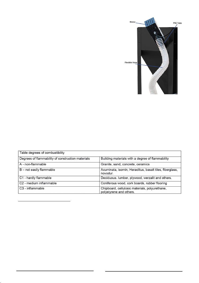
Safe distances: When installing the product a safe distance of at least 200 mm must be respected. is
distance applies to the product located near materials of B or C ammability level. e safe distance is
doubled if the product is close to materials of C3 combustion level.
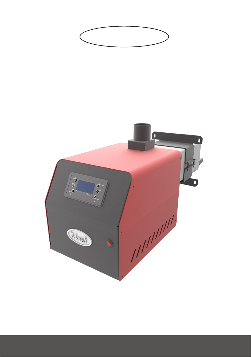
1. Description and advantages of pellet burner “SMB 100 Kw”
Pellet burners of this series are designed to utilize wood pellets. It has a welded steel construction. e result-
ing heat is absorbed by the heat exchange surface of the boiler body and transmitted the heating system. ese
boilers used for heating in local heating systems, but also for heating domestic water.
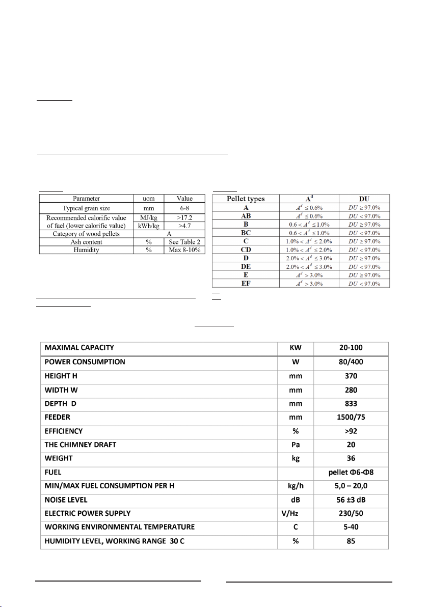
Automated pellet burner is part of the system and can utilize the following types of fuel: Wood pellets size 6
and 8 mm Class A;
e facility comprises: pellet burner equipped with a control panel;
Advantages of the product:
• Designed to utilize pellets, making it cleaner for the environment;
• Price of pellets as a local energy source is lesser inuenced by world prices of fuel and thus the value of
the extracted heat is highly competitive in comparison to using conventional heat sources;
• Product is highly automated and can be used in systems with programmable room thermostat ensuring
maximum thermal comfort and fuel economy;
• Eciency;
• Low emissions;
• Compact design allowing for simple installation and easy maintenance and cleaning;
• Opportunity for domestic hot water (DHW);
• Minimal operating costs;
Basic information of pellet burner:
• e pellet burner is mounted horizontally secured by M8 screws.
• e pellet burner is an independent module that can be mounted on already installed boilers making it
compatible with wood pellets as a fuel source.
• e burner is equipped with a control panel.
• Wood pellets allow easy automation of the process of combustion and give high eciency. However,
the wood pellets and any other solid fuel also live ash, but its amount is less than what remains from
rewood or coal.

3
Mareli Systems
e pellet burner is a compact modular design with integrated elec-
tronic control unit, consisting of the following components:
1. Combustion chamber made of high quality stainless steel;
2. Grill in the combustion chamber that is easily removed and al-
lows for easy ash removal;
3. Air duct, which ensures an even supply of air for combustion and
cooling elements of the burner;
4. Electric heater, which ignites the fuel, positioned beneath the in-
clined portion of the combustion chamber;
5. Fan, equipped with a sensor for adjusting speed;
6. Photo-sensor, which monitors the combustion process and ap-
plies a corresponding program;
7. Emergency temperature sensor to prevent “Backre” in the pipe
of the unit;
8. Controller, which monitors and controls the burner and indicates
its mode of operation;
9. Connector auger, which realizes the power of the auger;
10. Interface panel equipped with indicator lights;
11. Transparent panel that shows the operation of the controller;
Electrically powered auger that transports fuel to the burner depending on the operating mode of the burner.
e screw consists of a compact geared motor with a built-in protection against overheating tube which trans-
ports fuel until it reaches the hole through which is supplied to the exible tube. e exible tube is made of
special heat-resistant material (which in the case of combustion does not emit toxic substances) and connects
the auger and pellet burner.
End view of the system for pellet burner auger
• e installation must be performed by a qualied expert in the eld of heating systems. e place and
way of connecting the burner must be chosen carefully, follow the safety instructions!!!
• Never try to make changes to the torch! It is forbidden to use ammable liquids for ignition! Main-
tenance should be done by an adult who is familiar with the operating conditions! Introduction of
inammable liquids in room with a working burner is strictly prohibited! Children should not be le
unattended in the room where the product is installed!
2. Measures to improve safety
• e burner is controlled by a microprocessor.
• e process of ignition is monitored by a photo sensor, if there is no ignite the rst time, the micropro-
cessor feeds a second dose of pellets and ignition starts again. If aer 2 attempts ignition does not take
place burner goes into standby mode.
• If the hopper has no more pellets, the burner will not ignite.
• Flexible pipe for transporting the pellets is made from heat-resistant material. If during operation tem-
perature sensor detects a temperature higher than 90 ° C, the auger conveyor stops and the burner is
turned o. e temperature has to fall below 90 ° C, for the safety measures to stop .

4
Mareli Systems
3. Connection (installation) to the boiler:
e pellet burner can be attached to a steel or cast-
iron boiler with power from 20 to 100kW. e min-
imum depth of the combustion chamber should be
450 mm. Pellet burner without secondary air supply.
• Distance between the ame and the cooling
surface of the boiler 150mm.
• e unit is located so that there is enough space
for cleaning, removing ash from the burner,
boiler and exhaust pipes.
• Putting objects on the unit is forbidden, so
as not to break the seal. ere is a danger of
breaking and violating the integrity of the
burner.
• e opening for installation of the burner must have a width 174 mm and height of 140 mm. e size of
the door, to be joined must allow for the incision of the above-described mounting hole (if there is none).
• e burner is installed in the boiler door with the corresponding seal. Secured tightly with screws M8.
e relationship between the burner and boiler should be well sealed in order not to get gas leaks into the
room. When installing the equipment is in optimal horizontal position and the inlet hose pellets should
be straight and clamps must be properly tightened.
Appendix 1
Reconstruction of hot water boiler with automated burner
• Cut a hole in the available door (if there is no such planned). e sizes described in the instructions
should be respected.
• oroughly clean the interior walls of the boiler from ash residue, soot, etc., which would have led to
appearance of thermal resistance during operation. Aer cleaning, the drawer for collection of the ash
from the combustion chamber must also be taken out.
• en, mount and securely attach a pellet burner to the door through M8 screws (which are screwed,
where the thread is made on the door itself), which holds the burner to the door.
Explanation: It must be checked whether sealing ropes of the doors t snugly to the boiler housing. If any
gaps are found, the corresponding sealing rope must be replaced and ensure the density of this zone;
• Install the fuel supply conveyor, which feeds the automated pellet burner.
CAUTION: Before installation of the valve must be drained circulating water from it!
• Install the fuel transport auger that feeds the pellet burner.
e fuel supply conveyor must be installed in such a way so that fuel can be freely extracted from the hopper
– from its lowest point. In the event that the hopper is made/assembled on site, it is recommended to make
a manhole for servicing the rowing area of the screw conveyor. e screw conveyor pipe itself also must be
fastened, so as to ensure against upheaval and possible change of the screw conveyor axis angle against the
horizontal plane.
Explanation: e tilt angle (between the screw conveyor axis and the horizontal plane) of the screw conveyor
has a direct eect on its performance, i.e. the fuel ow which it will provide at a specied operating mode.
at is why adjustment of the burner settings is likely to be required upon change of this angle, in order to
insure specic heating power.
• Provide the power supply directly through a plug. Before connecting to the power the burner must be
earthed through a 4 mm2 copper wire with yellow-green insulation.
Power supply is provided through a Shockproof type plug directly in the mains.
CAUTION! e burner control unit should be plugged into an outlet, which must be earthed. ere is a risk
of electric shock in the absence of earthed plug! e manufacturer bears no responsibility!

5
Mareli Systems
Pellets are stored in a hopper. Mareli hoppers have a 45-degree tilt. e screw conveyor pipe must be placed
therein. e Screw conveyor draws pellets from the hopper and feeds the burner through a exible connection.
Dosing is controlled by the control unit by changing the operating time of the screw conveyor. e initial load-
ing of the screw conveyor with pellets (lling the screw conveyor pipe) is carried out when the screw conveyor
plug is connected to a normal 230V/50Hz outlet. As pellets start to fall through the exible connection, the
plug is shied to the burner.
Important: For ensuring normal operation of the burner a 20 Pa chimney draught is required. Aer starting
the burner, wait for about 3 hours for the chimney to be warmed up and measure the draught. Install addition-
al chimney fan (controlled by the control unit of the burner) if necessary.
e heat exchange surface is made of high quality low-carbon stainless steel. Wear is extremely slow, and
cleaning is done with a so damp cloth without any cleaners.
4. Maintenance and operation of the pellet burner
Requirements for the characteristics of the fuel, which is used for operation of a pellet burner SMB 100
e following table shows the requirements for the types of wood pellets utilized in automated pellet burner.
Tabl e 1
e following table shows classication of wood pel-
lets depending on their physical parameters - accord-
ing to an evaluation methodology applied by Mareli
Systems:
Tabl e 2
Ad - ash content in dry mass
DU - Mechanical resistance
Pellets are stored in a pellet hopper at a dry and
ventilated place.
Appendix 2
Technical data

6
Mareli Systems
e joint operation of the system which the automated pellet burner applies to / depends on:
• Heat output to which the burner is set;
• e heating surfaces of the heater, for which it is intended.
• e seal degree of the door and covers of the combustion chamber (condition of sealing ropes);
• Chimney draught;
Good chimney draught is essential for proper functioning of the heating system. Boiler capacity and eco-
nomical operation depend largely on it. e heater can only be connected to a chimney with a good draught.
Attention: Suocation hazard due to lack of oxygen in the installation room.
• Ensure sucient fresh air supply through holes out.
• Risk of injury/damage to equipment due to lack of combustion air can lead to tar and noxious gas for-
mation.
• Ensure sucient fresh air supply through holes out.
• Notify the user of the installation that these holes must remain open.
NOTES:
When using the circulation pump for the transmission of heat energy from the hot water boiler to the heating
system,d it is not recommended that the return („cold “) water’s temperature is lower than 60oC. A local (in
the heat exchanger of the boiler) over-cooling of ue gases and condensing water vapour is possible, which is
one of the end products of fuel combustion.
Continued operation of the burner is not recommended when the heat rating is less than 50%, since such
operating modes are not ecient and not cost eective, unless the combustion process is not set up exactly in
such operating mode.
EXPLANATION: If the boiler has to operate in a heat power mode which is lower than 50%, it is recom-
mended that a heat accumulator is installed to the heating system which to ensure a reliable, economical, and
ecient operation of the boiler-burner system in the installation.
Why is regular maintenance important?
Heating systems should be maintained on a regular basis for the following reasons:
• To maintain high eciency and to operate the heating system economically (with low fuel consumption);
• Achieving high safety of operation;
• Achieving high environment-friendly combustion;
5. Pellet burner cleaning
e appliance must be cleaned regularly for long and good operation of the pellet burner. Cleaning is done
when the burner is stopped and switched o from the mains. e more qualitative the pellets used are, the
longer the intervals between cleaning will be.
e main elements in the burner to be cleaned are the grate and the photo sensor.
It is mandatory daily cleaning of the basin. Cleaning takes about 5 minutes.
Cleaning sequence:
1. Turn o the burner.
2. Wait for the fan to blow out and cool down the burner. e
display will show OFF.
3. Switch to OFF the power supply button.
4. Open the boiler door.
5. Using gloves or pliers (temperature is still high), remove the
grate and clean it.
6. Place the grate back into the burner.
7. Make sure the basin stops are in position. Improper installa-
tion will result in auto-shut o of the burner thereaer.
8. Switch to ON the power supply button.
9. Start the burner.
Clean the photo sensor once per every 2 months or more oen if necessary. Simply open the top cover of the
burner by unscrewing the xing screws. e photo sensor is located in the upper le corner. Remove the xing
screw and clean with a dry so cloth. Check the fan, and clean it if necessary.
Do not use any cleaning agents.!
Boiler: Clean the ashes from the boiler with a brush and remove the soot.
Pellet hopper: Clean the pellet hopper periodically. When using lower quality pellets, they generate ash, which
accumulates on the hopper base and impedes the passage of the pellets.

7
Mareli Systems
Additional instructions:
1. Remove the ash and slag from the boiler once a week or according to the volume of ashtray.
2. Check boiler ues periodically and clean them if there is congestion.
3. Check the burner adjustment once a year using a gas analyser.
4. Clean ash at the pellet hopper bottom once a year.
5. Clean boiler chimney once every two years.
6. If there is law draught in the chimney, install additional chimney suction fan. Its control is planned and
integrated in the control unit of the burner.
e maintenance timetable is recommended, cleaning must be made whenever necessary.
e need of cleaning varies individually, since the choice of pellets, the system itself, and the settings of the
burner aect the frequency of cleaning. Unforeseen risks upon cleaning and maintenance.
Hand burn hazard: Possible reason – high temperature in the burning chamber. is risk exists in case of
unburned fuel pellet, as well as not cooled burner when cleaning by the user!
It may occur upon cleaning and maintenance of the burner. e use of special protective equipment (gloves)
is recommended!
Electrical shock hazard: e maintenance of the burner during operation as well as under voltage is pro-
hibited! If a short circuit or possible damage occurs, an authorised technician should be called. Touching the
conducting parts is prohibited!
Dust in eye hazard: May occur during work both upon cleaning and maintenance. e use of special protec-
tive equipment (safety goggles, tightly tted) is recommended!
CAUTION: Periodic cleaning, as well as supervision of the burner will prevent any incidents caused by faulty
pellet fuel, incorrect slopes of burner and of screw conveyor, as well as incorrect combustion settings. Read this
manual before installing and working with the burner. e manufacturer bears no responsibility!
A burner with properly adjusted settings operates well and cost-eciently. If there are problems, please, con-
tact the supplier for the removal of any defects or for setting up the burner.
POSSIBLE FAULTS AND TROUBLESHOOTING:
e verication shall be carried out only by a qualied electrical technician or an authorized by Mareli Systems
service centre.
e unit does not work:
• Check the hopper for sucient quantity of pellets.
• Check operation of the heater.
• Check operation of the screw conveyor (whether it feeds pellets). Check the exible connection. e
facility does not start: (display is not illuminated).
• Check fuses on the circuit board.
• Check the power source for loose connections.
ATTENTION! CUT OFF THE POWER SUPPLY.
Ignition failure:
• e initial dose of pellets is insucient (increase parameter 02)
Faulty heater - check it with a multimeter
• High fan speed (decrease parameter 04)
Fuel feeding is OK, but the ignition fails:
• Check the igniting heater with a multimeter;
• Check the voltage supplied to the igniting heater with a multimeter;
• Upon interruption of the facility’s operation (poor combustion, etc.) check the condition of the ue and
clean any debris and soot caused by the condensation.

8
Mareli Systems
It is important that faulty parts to be replaced immediately !!!
Always keep in stock additional photo sensor and heater for replacement.
At the end of the period, upon decommissioning the burner, clean the fuel surfaces from any deposits. Clean
the screw conveyor and the hopper from residual sawdust. Cut o the burner power supply.
Additional information:
1. Cables of the thermal sensors can be extended up to 10 m.
2. Installation of the thermal sensors should be done with immersion sleeves or applied under insulation
pipes.
3. Sensors are part of the controller. Do not replace them with others.
4. Indoor thermostats with relay output must be used.
5. Bedroom thermostat cable section - 2x0.75mm2
6. e required chimney draught is at least 20 Pa. Install additional chimney fan (controlled by the control
unit of the burner) if the values are lower.
7. When wiring pumps or a chimney fan, the wiring inputs in the housing of the burner must be used. If
there is a shortage of inputs, additional inputs must be installed.
8. e burner ignites more easily at low fan speed. Carefully adjust parameter 04. Recommended values
are 15-18%.
9. e time for pellet loading before ignition - parameter 02 (rst dose), must be sucient so that the
fallen pellets.
Cover the holes in the combustion basin.
10. e initial ignition of pellets produces large volume of smoke. If there is no additional chimney fan,
smoke leakage is possible through the seals on the boiler doors. e smoke usually disappears during
normal operation.
11. To achieve the desired output of the burner, do the following:
• Start the burner and wait it to go to the 5-th degree of power.
• Remove the photoelectric cell from the connector and keep light conditions of the photo-
electric cell over 100 units.
• Disconnect the exible connection from the burner and collect the pellets passed from the
conveyor into a bag for 10 min.
• Weigh the pellets passed and multiply by the factor 0.03.
• e calculated value is the power in KW/h.
• Example: If the screw conveyor passes 1,300 g pellets for 10 min. 1,300x0.03 = 39 Kw/h -
heating power.
12. It is recommended that the time for pellet feeding is half of the time for rest.
13. Indoor thermostat is connected to a lter for about 3 minutes. is means that the START signal from
the thermostat shall be read as such 3 min. aer it has been reported to the control unit. It is similarly
for the STOP signal. If there is a signal of overheating from the back combustion sensor, the fan of the
burner continues to operate for about 5 minutes in order to purge and cool.
14. If during the winter period the facility will not use, the installation must be drained or lled with
non-freezing uid (polypropylene glycol).
Instructions for installer and service technician:
Screw conveyor installation:
Install the screw conveyor at an angle of 45 0 into the pellet hopper.
Fill the hopper and plug the screw conveyor to 230V/ 50Hz. Wait for the screw conveyor pipe to be lled with
pellets and switch the plug to the burner. In order to ensure the normal free-fall of the pellets from the screw
conveyor to the burner, the exible connection must be well tensioned and the dierence in levels between the
screw conveyor outlet and the burner input shall be at least 40 cm.
Parameter adjustment:
e fuel process of the burner depends on several parameters. Fan speed (in percentages), time for feeding
pellets from the screw conveyor (s), time for the rest of the screw conveyor (s). ese parameters are adjusted
separately for the ve degrees of power. e degrees are upstream. It is not recommended that the power of
the rst or second degree is greater than the power of third, fourth, and h. For the recommended settings,
please refer to the manual for programming the controller of the pellet combustion system.

9
Mareli Systems
If the facility does not operate satisfactorily:
• Check the quality of pellets (must be free from dust). Upon normal operation of the burner, the quantity
of the pellets on the grate (combustion basin) must be such so that its holes are covered.
• Check the exhaust temperature (175- 240°C).
• If the temperature is very high, decrease the pellets fed. If the temperature is very low, increase the
amount of input air.
It is important to replace faulty parts immediately!!!
Always keep in stock additional photo sensor and heater for replacement.
e criterion for good operation of the burner is the colour of the ame - IT MUST BE YELLOW. When it is
dark red, mixed with smoke it is most likely that the volume of input air is less than required for good com-
bustion and must be increased.
Adjustment of the air aects essentially the combustion mode, the aim must be a calm, stable combustion,
without residue.
Sometimes, if the initial loading dose for ignition is large (Parameter 02), “choking” of the burner may occur,
i.e. it may not ignite and upon re-activation of the ignition (second attempt) the basin may clog up with pel-
lets. e volume of the rst dose must be decreased so as to avoid choking.
NOTE: It is desirable when adjusting the burner settings to use exhaust gas analyser.
IMPORTANT:
Default values of the parameters should not be taken for granted. e settings must be adjusted individually
according to REQUIRED POWER, TILT OF THE SCREW CONVEYOR, QUALITY OF PELLETS, CHIM-
NEY DRAUGHT, CUSTOMER REQUIREMENTS!
Switching o the burner and the boiler
Switching o the automated pellet burner should be done according to the guidelines in its manual. Aer
cooling of the boiler, the burner also should be switched o. It is also recommended that the facility is cleaned
from the accumulated ash.
An emergency stop of burner and boiler
During operation of the automated pellet burner an emergency situation may arise. Some situations of this
kind are recorded by the burner controller and a procedure for their prevention is automatically performed.
e monitoring controller also indicates the burner status. In the event of an accident check the reason for its
occurrence and take appropriate measures for its removal.
ATTENTION: In the event of emergency situation - overheating the boiler, the additionally mounted manda-
tory emergency thermostat is activated. Determine the cause of this accident and take appropriate measures
for its removal. is thermostat must be manually switched by unscrewing and removing the protective cap
and pressing its button until it switches, then replace back the protective cap. Also, the burner needs to be
restarted by switching it o and on.

10
Mareli Systems
Faults and Troubleshooting
In the presence of a fault in the operation of the burner-boiler system, one should be familiar with the prob-
lems and how to solve them as described in the user manual for operation of steel hot water boiler, as well as
in such for automated pellet burner. In the following table this information is supplemented by data that will
be of assistance to the service technician.
In case of a failure, try to repair it or inform a heating specialist. As an installation user you may only make
repairs, which involve just a simple replacement of the grate.
In case of „rst “commissioning of the boiler condensation of water vapour on the heating surfaces of the heat
exchanger may occur. is one-time process does not cause problems in the operation of the facility;
Operation of the automated pellet burner in modes, which exceed its heating power according to its technical
parameters, is not allowed. In the case of exceeded rated thermal power of the automated pellet burner irrev-
ocable deformations may occur in the area of the combustion chamber of the burner, which lead to its failure
– in such cases the factory warranty of the burner is not recognized by the manufacturer.

11
Mareli Systems
The main frame shows:
time and date, chrono activation, combustion
power and recipe, functioning state, error code,
main temperature, main thermostat,
summer/winter mode.
Button
Function
P1
P2
P3
P4
P5
P6
Exit Menu/Submenu;
Ignition and extinguishing (push for 3 seconds), Reset errors (push for 3 seconds), Enable/disable chrono;
Enter in User Menu 1/submenu, Enter in User Menu 2 (push for 3 seconds), Save data;
Enter in Visualizations Menu, Increase
Activation chrono time band
Enter in Visualizations Menu, Decrease
Led
Function
D1
D9
D2
D10
D3
D11
D5
D12
Auger ON
V2: Pump 1 ON
R: Igniter ON
Aux2: Pump 2 ON
External Chrono reached
Lack of pellet
Local Room Thermostat reached
Sanitary water demand
Er01 - Security Error High Voltage 1. It may also intervene with the system o;
Er02 - Security Error High Voltage 2. It can only intervene if the Combustion fan is active;
Er03 - Extinguishing for low exhaust temperature or missing light in the brazier;
Er04 - Extinguishing for water over temperature;
Er05 - Extinguishing due to high exhaust temperature;
Er06 - Pellet Thermostat open (ame return from the brazier);
Er07 - Encoder Error. The error may occur due to lack signal from Encoder;
Er08 - Encoder Error. The error can occur due to problems of adjustment of the number of revolutions;
Er09 - Water pressure low;
Er10 - Water pressure high;
Er11 - Clock Error. The error occurs due to problems with the internal clock;
Er12 - Extinguishing for ignition failure;
Er15 - Extinguishing due to power failure for more than 50 minutes;
Er16 - RS485 communication error (Display);
Er17 - Adjusting the Air Flow Failed;
Er18 - No more Pellet in the bunker;
Er23 - Boiler probe or Back boiler probe or probe Buer open;
Er25 - Engine cleaning brazier broken;
Er26 - Engine cleaning broken;
Er27 - Engine cleaning 2 broken;
Er34 - Depression below the minimum threshold;
Er35 - Depression above the maximum threshold;
Er39 - Sensor Flowmeter broken;
Er41 - Minimum air ow in Check Up is not reached;
Er42 - Maximum air ow exceeded;
Er44 - Open door error;
Er47 - Error Encoder Auger: missing signal Encoder;
Er48 - Error Encoder Auger: Auger regulation speed not achieved;
Er52 - Error Module I/O I2C;
Er57 - Test ’Forced Draught High’ in Check Up fail ;
Service - Service error. It noties that the planned hours of functioning is reached. It is necessary to call for service.
ALARMS
CONTROL PANEL: USE AND FUNCTIONS

12
Mareli Systems
Description
Code
Sond
Hi
Clean
Port
Ignition
block
Cleaning on
Link Error
Anomaly of the probes checking, during Check Up phase.
Room temperature greater than 99 °C.
This message noties that the planned hours of functioning are reached.
Door Open.
The message appears if the system is turned o during Ignition (after Preload) not manually:
the system will stop only when it goes in Run Mode.
Periodical Cleaning in progress.
No communication between motherboard and keyboard
MESSAGES
Exhaust T. [°C] - Exhaust temperature;
Room T. [°C] - Local room temperature; it is visible only if;
Buer T. [°C] - Buer Temperature;
Pressure [mbar] - Water pressure;
Air Flux - Air ow;
Fan Speed [rpm] - Exhaust fan speed;
Auger [s] - Auger work time;
Recipe [nr] - Combustion recipe set;
Product Code: 510 - Product code;
VISUALIZATIONS
USER MENU 1
Combustion Management
Power - In this menu is possible to modify the combustion power of the system. It can be set in automatic or
manual modality . In the rst case the system chooses the combustion power. In the second case the user selects
the desired power. On the left side of the display are signalled the combustion modality (A=automatic combustion,
M=manual combustion) and the working power of the system.
Recipe - Menu to select the combustion recipe. The maximum value is the number of recipes visible to the user.
Auger Calibration - It allows to modify the value set in rm of Auger’s speed or On times. The values are in the
range – 7 ÷ 7. The rm’s value is 0.
Fan Calibration - It allows to modify the value set in rm of Combustion Fan’s speed. The values are in the range
– 7 ÷ 7. The rm’s value is 0.
Heating Management
Boiler thermostat - Menu to change the value of the boiler thermostat .
Buer thermostat - Menu to change the value of the Buer Thermostat.
Room Thermostat - This Menu allows to modify the Local Room Thermostat’s value. It is visible only if the ambient
probe is select.
Summer-Winter - Menu that allows the selection Summer-Winter.
Manual Load
The procedure activates the pellet manual loading with activation in continue modality of the Auger engine. The
loading is stopped automatically after 600 seconds. The system must be OFF for the function can be activated.
Cleaning Reset
Menu to reset the ‘System Maintenance 2’ function.

13
Mareli Systems
CHRONO
This Manu allows selecting the programming modalities and and the Ignition/Extinguishing time slots.
Disable
Daily
Weekly
Week-End
Modality - It allows selecting the disired modality, or disable all set programming.
1. Enter modication mode through the key P3.
2. Select the chosen modality (Daily, Weekly or Week end).
3. Enable/disable chrono modality through the keys P2.
4. Save the settings through the keys P3.
Programming
The system includes three type of programming: Daily, Weekly, Week end.
After selecting the desired kind of programming:
1. Select the programming time through the keys P4/P6.
2. Enterthe adjustment modality (selected time will be ashing) through the keys P3.
3. Change the time via keys P4/P6.
4. Save the programmong with the keys P3.
5. Enable (a “V” is displayed) or disable the time slot (a “V” is not displayed”) by
pressing the keys P5.
Daily
Select the day of the week to program and set the ignition and extinguishing times.
Programs around midnight
Set the clock On of the previous day at the desired time: Ex. 20.30
Set the clock of OFF of the previous day at: 23:59
Set the clock On of the following day at 00:00
Set the clock of OFF of the following day at the desired time: Ex. 6:30
The system turns on at 20.30 on Tuesday and turns o at 6.30 on Wednesday
Weekly
The programs are the same for all days of the week.
Week-end
Choose between 'Monday-Friday' and 'Saturday-Sunday' and then set the switching
on and o times.
Monday
ON OFF
09:30 11:15 V
00:00 00:00
00:00 00:00
Monday____________
Tuesday
Wednesday
Thrusday
Friday
Mon-Fri
Sat-Sun
USER MENU 2
Menu is accessed by pressing the P3 buttons for 3 seconds .
Keyboard Settings
Time and Date - Used to set the day, month, year and current time.
Language - Menu to modify the language of the LCD board.
Keyboard Menu
Set Contrast - Menu used to regulate the display contrast.
Set Minimum Light - Menu used to regulate the lighting of the display when the command aren’t used.
Keyboard Address - It allows to change the address of the RS485 node. In the RS485 bus it is not possible to
have more nodes with the same address. It is possible to congure the keyboard as local or remote by changing
the address (16 for local , 17 for remote).
Node List - This menu shows: communication address of the board, typology of the board, rmware code and
rmware version. Data are not modiable. The typologies of board that can appear are:
MSTR - Master; INP - Input; KEYB - Keyboard; OUT - Output;
CMPS - Composite; SENS - Sensor; COM - Communication;
Acoustic Alarm - It allows to enable or disable the acoustic alarm of the keyboard.

14
Mareli Systems
WIRING DIAGRAM

15
Mareli Systems

MARELI SYSTEMS disclaims any responsibility for possible inaccuracies contained in this manu-
al if they are due to printing or transcription errors. We reserve the right to make any change that
appears to be necessary or useful without harm the essential characteristics.
Mareli Systems
Mareli Systems
Industrial Zone
Simitli, 2730
Region Blagoevgrad
Bulgaria
info@mareli-systems.com
www.mareli-systems.com
Table of contents
Other Mareli Systems Burner manuals
Popular Burner manuals by other brands

CITERM
CITERM GP Technical Documentation and Operation Manual

Goldair
Goldair Antares GBQ275 operating instructions

Riello
Riello BG6.1D Installation, use and maintenance instructions

Ecoflam
Ecoflam Multicalor 500.1 PR manual

Ignis
Ignis EB1400 User's manual & installation instructions

Frigidaire
Frigidaire Side Burner use and care manual

Riello
Riello 554T40 Installation, use and maintenance instructions

CSA
CSA OVE LP owner's manual

Ragalta
Ragalta RCB-20 instruction manual

elco
elco N8 GL-E/BT3 Series Hydraulic schematics

Weishaupt
Weishaupt WL30Z-C 4LN manual

Lamborghini Caloreclima
Lamborghini Caloreclima PNZ 30 Assembly, Use, Maintenance Manual