Marlo Incorporated MGTE Series User manual

“MGTE” Series
1 1/2” Metered & Time Clock
COMMERCIAL WATER CONDITIONERS
INSTALLATION, OPERATION,
AND MAINTENANCE MANUAL
MODEL NO:
SERIAL NO:
DATE INSTALLED:
DEALER:
COMPLETE FOR FUTURE REFERENCE:
Marlo Incorporated
2227 South Street
P.O. Box 044170
Racine, WI 53404-7003
Ph. (262) 681-1300
Fax (262) 681-1318
www.Marlo-Inc.com
8-193 R1

MGTE 1-1/2” METERED & TIMECLOCK
Phone: (262) 681-1300 • Web: www.Marlo-Inc.com • E-mail: [email protected]
TABLE OF CONTENTS
SYSTEM INFORMATION
Product Warranty ...........................................................................................................................................................1
Specication Table ........................................................................................................................................................2
General Arrangement Drawing .....................................................................................................................................3
INSTALLATION
Installation Instructions ..................................................................................................................................................4
Program Lockout Feature .............................................................................................................................................6
Control Valve Function & Cycles of Operation ..............................................................................................................7
OPERATION
Installer Display Settings ...............................................................................................................................................8
Setting Options ............................................................................................................................................................13
Valve Cycle Positions .................................................................................................................................................14
MAINTENANCE
MGTE Control Valve Parts List ....................................................................................................................................17
Injector Body Rell Assembly Parts .............................................................................................................................21
Drain Line Flow Control Parts .....................................................................................................................................22
Meter Assemblies ........................................................................................................................................................23
Troubleshooting ...........................................................................................................................................................24

MGTE 1-1/2” METERED & TIMECLOCK
SYSTEM INFORMATION
1
Phone: (262) 681-1300 • Web: www.Marlo-Inc.com • E-mail: [email protected]
COMMERCIAL AND INDUSTRIAL PRODUCT WARRANTY
Marlo, Inc. warrants all commercial and industrial water treatment products manufactured and/or distributed by it to be
free from defects in materials and workmanship for a period of one (1) year from the date of shipment. The berglass
mineral tank(s) alone have a warranty for a period of ve (5) year from the date of shipment. If within that period any
products shall be proven to Marlo, Inc.’s satisfaction to be defective, those products will be replaced or the price
refunded at Marlo Inc.’s option.
Marlo Inc.’s obligations or nonperformance, defective, or any damage caused by its products or their use, and buyer’s
exclusive remedy therefore, shall be limited to product replacement or refund and shall be conditioned upon Marlo
Inc.’s receiving written notice together with a demand for such replacement or refund:
The foregoing warranty is exclusive and in lieu of all other expressed implied warranty (except of title) including but
not limited to implied warranty of merchantability and tness for particular purpose.
Marlo Inc. will not be subject to and disclaims the following:
1. Any other obligations or liabilities arising out of breach of contract or out of warranty.
2. Any obligations whatsoever arising from tort claims (including negligence and strict liability or arising under other
theories of law with respect to products sold or services rendered by Marlo Inc. or any undertakings, acts, or
omissions relating thereto.
3. All consequential, incidental, and contingent damages.
Labor charges, charge backs or handling charges are excluded from Marlo Inc.’s warranty provisions.
COMMERCIAL AND INDUSTRIAL WATER SOFTENER GUARANTEE
Under normal operating conditions:
1. The softener efuent shall be zero soft as determined by a soap test.
2. The loss of softening resin through attrition during the rst three (3) years shall not exceed 3% per year.
3. The softening resin shall not be washed out of the system during backwash.
4. The color and turbidity of the softener efuent shall not be greater than the incoming water.
Any mechanical equipment proving defective in workmanship or material within one year after installation or eighteen
(18) months after shipment, whichever comes rst, shall be replaced FOB factory.

MGTE 1-1/2” METERED & TIMECLOCK
SYSTEM INFORMATION
2
Phone: (262) 681-1300 • Web: www.Marlo-Inc.com • E-mail: [email protected]
SPECIFICATION CHART
SYSTEM SIZE
1-1/2” MGTE MODEL 60 90 120 150 210 300
VALVE SIZE (IN) 1-½ 1-½ 1-½ 1-½ 1-½ 1-½
MAX CAPACITY (KILOGRAINS) 60 90 120 150 210 300
MIN CAPACITY (KILOGRAINS) 40 60 80 100 140 200
FLOWRATE (GPM)
CONTINUOUS FLOWRATE (GPM) 35 33 34 37 39 42
PEAK FLOWRATE (GPM) 48 45 46 54 52 56
BACKWASH & FAST FLUSH (GPM) 3.2 4.2 5.3 7.5 11.0 15.0
BRINE DRAW & RINSE (GPM) 1.3 2.2 2.4 3.2 4.4 5.6
BRINE TANK REFILL (GPM) 0.5 0.5 0.5 0.5 0.5 0.5
TIMER
SETTINGS
BACKWASH & FAST FLUSH (MIN) 10 10 10 10 10 10
BRINE DRAW & RINSE (MIN) 60 60 60 60 60 60
FAST FLUSH (MIN) 10 10 10 10 10 10
BRINE TANK REFILL (MIN) 30 45 60 75 105 150
SOFTENER
TANK
SIZE (IN) 13x54 14x65 16x65 18x65 21x62 24x72
GRAVEL (LBS) 0 30 35 40 80 120
RESIN (FT3)2345710
FREEBOARD (IN) 16 21 21 24 18 21
BRINE SYSTEMS
EQUIPMENT
TANK SIZE 18x40 18x40 24x40 24x40 24x50 24x50
MAX SALT STORAGE (LBS) 290 290 565 665 575 430
INJECTOR CODE 15C 15D 15E 15F 15G 15H
INJECTOR COLOR Red White Blue Yellow Green Orange
MAX
SALT DOSAGE (LBS) 30 45 60 75 105 150
REFILL TIME (MIN) 20 30 40 50 70 100
MIN
SALT DOSAGE (LBS) 12 18 24 30 42 60
REFILL TIME (MIN) 8 12 16 20 28 40
MAX
REGENERATION PER
SALT REFILL
1069762
MIN
26 15 23 17 17 6
REGENERATION WASTE VOLUME (GAL) 119 177 207 289 411 554
DIMENSIONS (LxWxH) 37x18x65 38x18x76 46x24x76 48x24x78 51x24x78 54x24x86
NOTES:
1. FLOW RATES
Continuous: pressure loss does not exceed 15 psig.
Peak: pressure loss does not exceed 25 psig
Backwash & Flush: maximum ow to drain
Brine & Rinse: Injector ow to drain @50 psi inlet pressure
Brine Tank Rell: ow to rell Brine Tank
2. SOFTENER TANK
Freeboard: distance in inches from surface of resin to top sealing ange of tank
3. SALT DOSAGE
Maximum 15 lbs./cu.ft. - regeneration efciency: 2,000 grains/pound of salt (factory setting)
Maximum 6 lbs./cu.ft. - regeneration efciency: 3,000 grains/pound of salt
4. REGENERATION WASTE VOLUME - Total gallons water discharged per regeneration
5. DIMENSIONS:
Leave a minimum 24 inch clearance to the height of the unit for loading media.
Dimensions are for general arrangement use only.

MGTE 1-1/2” METERED & TIMECLOCK
SYSTEM INFORMATION
3
Phone: (262) 681-1300 • Web: www.Marlo-Inc.com • E-mail: [email protected]

MGTE 1-1/2” METERED & TIMECLOCK
INSTALLATION
4
Phone: (262) 681-1300 • Web: www.Marlo-Inc.com • E-mail: [email protected]
INSTALLATION INSTRUCTIONS
A. GENERAL
1. Shut off all water at main supply valve.
2. Shut off the fuel supply to water heater.
3. Open faucets (hot and cold) nearest pump or water meter to relieve pressure and drain system.
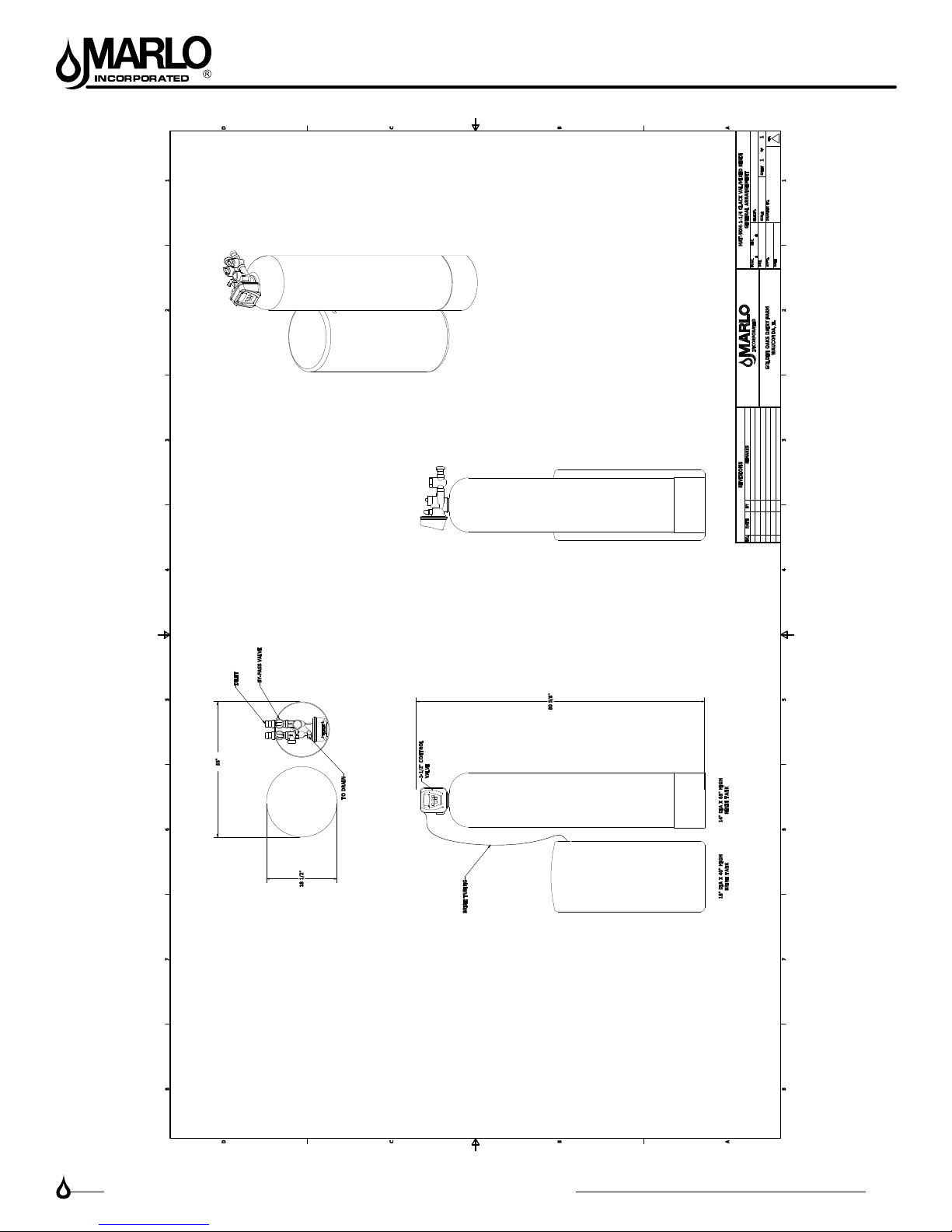
4. Move softener into the installation position.
5. Level the unit. Place shims under cabinet or brine tank as needed. (Do Not use metal shims.)
6. Cut the cold water supply line as required.
B. PLANNING INSTALLATION
1. All installation procedures must conform to local plumbing, electrical and sanitation codes and ordinances.
2. It is recommended that outside faucets for lawn service be on the hard water line, ahead of the softener, to
conserve softened water, save salt and prevent lawn damage.
3. CAUTION: The inlet water temperature MUST NOT exceed 1100 F.
4. Do not locate softener where ambient temperature drops below 400 F.
5. Allow space around the softener for ease of servicing.
6. The softener drain lines must never be solidly connected to the sewer line. (Always provide an air gap at
the END of the drain line). Valve drain line must not be elevated over 5’ from the top of the softener on well
systems, and not over 8’ on municipal water systems.
7. The salt storage cabinet or brine tank is a gravity drain, and this drain line must be lower than the drain t-
ting on the side wall of the cabinet.
8. Move the softener into position. MGTE-60 systems have been pre-loaded at the factory. For systems larger
than the MGTE-60, complete section C before continuing on to section D.
9. IMPORTANT: Be sure that the water inlet line is connected to the “inlet” side of the valve. If water lines
are reverse, (inlet/outlet) resin may be forced from the water softener into the plumbing system. If this
occurs,the plumbing system must be ushed clean.
C. LOAD SOFTENER TANK
Note: If the system is skid mounted, it will be prepiped and preloaded at the factory. Skip the following
instructions.
1. On Model MGTE-60 the softening media has been pre-loaded at the factory. Skip this section and go to
“Mounting Control Valve Assembly”.
2. Fill a tank approximately 1/3 full of water using a hose, bucket, etc. Plug the PVC distributor manifold ..
pipe using a plastic cap, cork, rag, etc. No gravel or resin should go into this distributor manifold pipe.
3. Verify the distributor manifold is center in the tank with the distributor resting on the bottom of the tank.
Verify the riser pipe is still plugged.
Note: Reference the specication table in the front of this manual for the correct quantities of gravel and
resin. Make sure you have the required amounts on site before you begin.
4. With care not to damage any lateral, pour in the gravel provided for each tank through the top opening in
the tank and level out evenly. This will cover the distributor assembly.
Note: Wetting the gravel in the bags before loading will eliminate the normal amount of dust.
5. When gravel is loaded and leveling is completed, proceed as follows:
6. With the distributor riser pipe still plugged, add the proper amount of resin supplied through the top
opening in the tank.
Caution: The softener resin is very slippery. Take care when stepping on any spilled resin. Remove spilled
resin from standing surface immediately.
7. When loading is complete, remove plastic cap, cork, or rag that was used to plug the distributor riser
pipe. Be careful not to let any foreign debris fall into the pipe. The result could be damage. Repeat steps 1-7
for each softener tank (if applicable).

MGTE 1-1/2” METERED & TIMECLOCK
INSTALLATION
5
Phone: (262) 681-1300 • Web: www.Marlo-Inc.com • E-mail: [email protected]
INSTALLATION INSTRUCTIONS
D. MOUNTING CONTROL VALVE ASSEMBLY
1. Verify that the distributor riser pipe is not plugged.
2. Lubricate the distributor o-ring on the bottom of the control valve with silicone.
3. Screw the control valve into top opening of tank making sure the distributor riser pipe slides easily through
the distributor o-ring. Care must be taken not to “nick” this o-ring as hard water leakage could result.
4. Tighten down the control valve to ensure positive o-ring seal at top of tank.
E. CONNECT ALL FITTINGS
CAUTION: Care must be used when working with copper tubing. Do not allow the ame from torch to
contact any noryl portion of the Valve assembly.
1. Attach a minimum of 3/4” drain line to drain elbow.
2. Do not elevate the drain line over 5’ above the top of the valve (8’ on municipal systems) or to exceed 25’ in
length at either height.
CAUTION: An air gap must be provided upon sewer entry. (Conform to local plumbing and sanitation
codes and ordinances).
3. The salt storage cabinet or brine tank provides an overow. Attach 1/2” ID exible plastic tubing to the over-
ow tting and direct it to the drain. DO NOT connect to the main drain line. Use a separate gravity ow
line.
F. PRESSURE TEST THE INSTALLATION
The plumbing system can now be checked for any possible leaks
1. Put the unit into backwash. To do this, push and hold the REGEN button for 3-5 seconds. When the Valve
stops cycling, unplug the unit. With water supply off, put the bypass into the service position.
2. Open water supply line valve very slowly. Water should escape slowly from the drain line. If water enters too
quickly, resin may be lost to the drain.
3. When all of the air has been purged from the mineral tank (water ows steadily from the drain) open the
main supply valve fully.
4. Allow water to run to drain until clear. CHECK FOR LEAKS!
5. Plug the unit back in.
6. Manually step the unit through the remaining steps, stopping at the ll cycle (to do this, push the REGEN
button. The unit will say Brine on the screen). Once the piston has stopped moving, push the REGEN but-
ton again to the next cycle. Continue until Fill appears on the screen. The unit will now ll the brine tank to
the appropriate level. (This sequnce is for softeners with post ll brine)
7. Allow control to return to the home position.
8. Check for leaks!
9. Make sure the power cord is plugged into a properly grounded wall receptacle.
G. MANUAL REGENERATION
The user can initiate manual regeneration. The user has the option to request a manual regeneration at the
delayed regeneration time or to have the regeneration occur immediately:
1. Pressing and releasing the REGEN button. “Regen Today” will ash on the display and the regeneration
will occur at the delayed regeneration time. The user can cancel the request by pressing and releasing
the REGEN button. This method of manually initiating regeneration is not allowed when the system is set to
immediately regenerate when the gallon capacity reaches zero.
2. Pressing and holding the REGEN button for approximately 3 seconds will immediately start the regeneration
The user cannot cancel this request.

MGTE 1-1/2” METERED & TIMECLOCK
INSTALLATION
6
Phone: (262) 681-1300 • Web: www.Marlo-Inc.com • E-mail: [email protected]
NOTE: Program Timer “Lockout” Feature
The Program Timer is initially set to allow access to all Programming, Diagnostic and History screens
The Installer can limit access to (lockout) most screens by activating the Lockout Feature.
Activating “Lockout” allows the user to view and change only Water Hardness, Days Override, Time of Regeneration
and Time of day.
Activate “Lockout” Feature: Press DOWN then NEXT then UP then SET CLOCK in sequence. LOCK will briey
appear in the display.
De-activate “Lockout” Feature: Press DOWN then NEXT then UP then SET CLOCK. UNLOCK will briey appear in
the display.
When in operation normal user displays such as time of day, gallons remaining or days remaining before regeneration
are shown. When stepping through a procedure if no buttons are pressed within ve minutes the display returns to a
normal user display. Any changes made prior to the ve minute time out are incorporated. The one exception is
current ow rate display under the diagnostic procedure. The current ow rate display has a 30 minute time
out feature.

MGTE 1-1/2” METERED & TIMECLOCK
INSTALLATION
7
Phone: (262) 681-1300 • Web: www.Marlo-Inc.com • E-mail: [email protected]
CONTROL VALVE FUNCTION AND CYCLES OF OPERATION
This low-lead brass fully automatic control valve is designed as the primary control center to direct and regulate
all cycles of a water softener or lter. When the control valve is set up as a softener, the control valve is set
to perform down ow regeneration. When the control valve is set up as a lter, the control valve can be set to perform
down ow regeneration or simply backwash. The control valve can be set to regenerate on demand (consumption of a
predetermined amount of water) and/or as a time clock (passage of a particular number of days).
The control valve is compatible with a variety of regenerants and resin cleaners. The control valve is capable of
routing the ow of water in the necessary paths to regenerate or backwash water treatment systems. The injector
regulates the ow of brine or other regenerants. The control valve regulates the ow rates for backwashing,
rinsing and the replenishing of treated water into a regenerant tank, when applicable.
The 1-1/2” control valve is designed to deliver high service (70 gpm @ 15 psig) and backwash (52 gpm @ 25 psig)
ow rates when the bypass has straight ttings and a 1.09” (1-1/2” Pipe) distributor. The control valve uses traditional
fasteners (e.g. screws), instead clips, threaded caps, nuts and snap type latches are used. Caps and nuts only need
to be rmly hand tightened because radial seals are used. Tools required to service the valve include one small blade
screwdriver, pliers and a pair of hands. Disassembly for servicing takes much less time than comparable products
currently on the market. Control valve installation is made easy because the distributor tube can be cut 1/2” above to
1/2” below the top of the tank thread. The distributor tube is held in place by an o-ring seal and the control valve also
has a bayonet lock feature for upper distributor baskets.
The transformer power pack comes with a 15-foot power cord and is designed for use with the control valve. The
transformer power pack is for dry location use only. The control valve remembers all settings for up to 8 hours if the
power goes out and the battery is not depleted. After 8 hours, the only item that needs to be reset is the time of day;
other values are permanently stored in the nonvolitile memory. If a power loss lasts less than 8 hours and the time
ashes on and off, the time of day should be reset and the non rechargeable battery should be replaced. The replace-
ment battery is a commercially available 3 volt Lithium coin cell type 2032..
Table 3 shows the order of the cycles when the valve is set up as a softener.
Table 3
Regeneration Cycles Time
Grains Capacity / LB NaC1
Lbs. NaC1/cu ft resin
1st Cycle: Backwash Normal
2nd Cycle: Brine Slowrinse
3rd Cycle: Backwash Normal
4th Cycle: Rinse
5th Cycle: Fill
Cycle
Time
In
Minutes
7.5 to 1.2
Down Flow Softener
10 minutes
60 minutes
0 minutes
10 minutes
minutes will vary depending on softener capacity
3500 to 2501
0.011–200
6th Cycle: End

MGTE 1-1/2” METERED & TIMECLOCK
OPERATION
8
Phone: (262) 681-1300 • Web: www.Marlo-Inc.com • E-mail: [email protected]
INSTALLER DISPLAY SETTINGS
“MGTE” Series Automatic Water Conditioners
6 8-192 R1
Installer Display Settings
STEP 1I - Press NEXT and UP simultaneously for 3 seconds.
STEP 2I – Hardness: The default is 20 with value ranges from 1 to 150 in 1
grain increments. Note: The grains per gallon can be increased if soluble iron
needs to be reduced.
Set the amount of hardness in grains of hardness as calcium carbonate per
gallon using DOWN or UP.
This display will not show if ‘AUTO’ is not selected in Set Volume Capacity in
OEM Softener System Setup. Press NEXT to go to step 3I. Press REGEN to
exit Installer Display Settings.
STEP 3I – Day Override: Number of days between regeneration (1 to 28); or
“OFF”.
If value set to “OFF”, regeneration initiation is based solely on volume used. If
value is set as a number (allowable range from 1 to 28) a regeneration
initiation will be called for on that day even if sufficient volume of water were
not used to call for a regeneration. Set Day Override using DOWN or UP.
When volume capacity is set to “OFF” (time clock), sets the number of days
between regenerations. When volume capacity is set to AUTO or to a number
(metered), sets the maximum number of days between regenerations. See
Setting Options Table 8 for more detail on setup. Press NEXT to go to step 4I.
Press REGEN to return to previous step.
STEP 4I – Next Regeneration Time (hour): The default time is 2:00 AM.
AM/PM toggles after 12.
Used for DELAY regeneration. Set the “hour” of day for regeneration using
DOWN or UP. If “IMMEDIATE” is selected in Set Regeneration Time Option in
OEM Softener System Setup, this display will show “REGEN IMMEDIATE ON
ZERO GAL”. Press NEXT to go to step 5I. Press REGEN to return to previous
step.
STEP 5I – Next Regeneration Time (minutes):
Used for DELAY regeneration. Set the “minutes” of day for regeneration using
DOWN or UP. This display will not be shown if “IMMEDIATE” is selected in
Set Regeneration Time Option in OEM Softener System Setup. Press NEXT
to go to Step 6I. Press REGEN to return to previous step.

MGTE 1-1/2” METERED & TIMECLOCK
OPERATION
9
Phone: (262) 681-1300 • Web: www.Marlo-Inc.com • E-mail: [email protected]
“MGTE” Series Automatic Water Conditioners
7 8-192 R1
STEP 6I – Energy Saver operation: Set to “OFF” or “ON”.
When set to OFF, the display backlight is always on. When set to ON, the
display backlight will go off after 5 minutes of no keypad activity.
A valve error or salt level alert will activate the display backlight, and prevent
deactivation until the error or alert is reset by the user. Press NEXT to exit
Installer Display Settings. Press REGEN to return to the previous step.
RETURN TO NORMAL MODE
User Display Settings
When the system is operating, several displays may be shown. Pressing
NEXT will alternate between the displays.
• Current TIME OF DAY.
• CAPACITY REMAINING is the gallons that will be treated before the
system goes through a regeneration cycle (Metered units only). Pressing
DOWN while in the Capacity Remaining display will decrease the
capacity remaining in 10 gallon increments and will also increase the
volume used impacting the recorded values in Diagnostics Steps 3D, 4D
and 5D and Valve History, Step 4VH.
• If a water meter is installed, GPM flashes (and alternates with the flow
rate) on the display when water is being treated (i.e. water is flowing
through the system).
• DAYS TO A REGEN is the number of days left before the system goes
through a regeneration cycle. Pressing UP or DOWN while in this screen
will temporarily increase or decrease the displayed value by 1 day.
• Contact information will be displayed if it was edited. For concerns with
phone number or banner text displays, contact OEM for instructions.
• DP or HOLD if the dP switch is closed.
• REGEN TODAY will alternate with the header on the display if the
system has called for a regeneration that will occur at the pre-set time of
regeneration.
• If Salt Level Monitor has be set to ON in Step 16S, the SALT LEVEL
screen will appear. To adjust the salt level, press CLOCK, and use UP
or DOWN to set the current value. The salt level is adjustable from 0 to
500 lbs. in 10 lb. increments
• REGEN PENDING will be displayed in Alternator Systems whenever a
unit is waiting to initiate the first cycle step of regeneration.
• STAND BY will be displayed in Alternator Systems when a valve is in
Standby state.
• DELAYED RINSE+FILL PENDING will be displayed whenever a zero-
capacity tank has transferred to an off-line state and is currently waiting
to initiate the second portion of a regeneration cycle. Viewed only when
Delayed Rinse and Fill is set to ON.

MGTE 1-1/2” METERED & TIMECLOCK
OPERATION
10
Phone: (262) 681-1300 • Web: www.Marlo-Inc.com • E-mail: [email protected]
“MGTE” Series Automatic Water Conditioners
8 8-192 R1
Regeneration Mode
Typically a system is set to regenerate at a time of low water usage. An
example of a time with low water usage is when a household is asleep. If
there is a demand for water when the system is regenerating, untreated water
will be used.
When the system begins to regenerate, the display will change to include
information about the step of the regeneration process and the time remaining
for that step to be completed. The system runs through the steps
automatically and will reset itself to provide treated water when the
regeneration has been completed.
Manual Regeneration
Sometimes there is a need to regenerate the system sooner than when the
system calls for it, usually referred to as manual regeneration. There may be
a period of heavy water usage because of guests or a heavy laundry day. To
initiate a manual regeneration at the preset delayed regeneration time, when
the regeneration time option is set to “DELAYED REGEN” or “DELAY +
IMMEDIATE”, press and release “REGEN”.
The words “REGEN TODAY” will periodically be shown
on the display to indicate that the system will regenerate
at the preset delayed regeneration time. If you pressed
the “REGEN” button in error, pressing the button again
will cancel the request.
Note: If the regeneration time option is set to “IMMEDIATE” there is no set
delayed regeneration time so “REGEN TODAY” will not activate if “REGEN”
button is pressed. To initiate a manual regeneration immediately, press and
hold the “REGEN” button for three seconds. The system will begin to
regenerate immediately. The request cannot be cancelled. Note: For
softeners, if brine tank does not contain salt, fill with salt and wait at least two
hours before regenerating.
Set Time of Day
The user can also set the time of day. Time of day should only need to be set
if the battery has been depleted because of extended power outages or when
daylight saving time begins or ends. If an extended power outage occurs, the
time of day will flash on and off which indicates the time of day should be
reset. The non rechargeable battery should also be replaced.
STEP 1U – Press CLOCK
STEP 2U - Current Time (hour): Set the hour of the day using DOWN or UP.
AM/PM toggles after 12. Press NEXT to go to Step 3U.

MGTE 1-1/2” METERED & TIMECLOCK
OPERATION
11
Phone: (262) 681-1300 • Web: www.Marlo-Inc.com • E-mail: [email protected]
“MGTE” Series Automatic Water Conditioners
9 8-192 R1
STEP 3U - Current Time (minutes): Set the minutes of the day using DOWN
or UP. Press NEXT to exit Set Time of Day. Press REGEN to return to
previous step.
RETURN TO NORMAL MODE
Power Loss
If the power goes out the system will keep time until the battery is depleted. If
an extended power outage occurs, the time of day will flash on and off which
indicates the time of day should be reset and the non rechargeable battery
replaced. The system will remember the rest.
Error Message
If the word “ERROR” and a number are displayed contact the OEM for help.
This indicates that the valve was not able to function properly. If the number
and banner text in the Contact Screens has been edited, the two displays
below will alternate.
Manufacturers Softener System Setup
Step 1S – Press NEXT and DOWN simultaneously for 3 seconds and
release. If screen in Step 2S does not appear in 5 seconds the lock on the
valve is activated. To unlock press DOWN, NEXT, UP, and SET CLOCK in
sequence, then press NEXT and DOWN simultaneously for 3 seconds and
release.
It is not necessary for the installer or end user to program these
screens. All screens have been programmed for your specific
equipment.
Step 2S – Choose SOFTENING using UP or DOWN. Press NEXT to go to
Step 3S. Press REGEN to exit OEM Softener System Setup.

MGTE 1-1/2” METERED & TIMECLOCK
OPERATION
12
Phone: (262) 681-1300 • Web: www.Marlo-Inc.com • E-mail: [email protected]
“MGTE” Series Automatic Water Conditioners
13 8-192 R1
Step 16S: Marlo does not turn this option on. Set Salt Level Monitor. This
screen will not appear if Step 2CS is set to 2.0. Press NEXT to exit Softener
System Setup. Press REGEN to return to the previous step.
All Marlo equipment has “OFF” as the default.
RETURN TO NORMAL MODE

MGTE 1-1/2” METERED & TIMECLOCK
OPERATION
13
Phone: (262) 681-1300 • Web: www.Marlo-Inc.com • E-mail: [email protected]
“MGTE” Series Automatic Water Conditioners
14 8-192 R1
Settings Options Table 8
Volume
Capacity
Regeneration
Time Option
Day
Override Result4
AUTO DELAYED
REGEN OFF
Reserve capacity automatically estimated.
Regeneration occurs when volume capacity falls below the reserve capacity at
the next Regen Set Time
AUTO DELAYED
REGEN
Any
number
Reserve capacity automatically estimated.
Regeneration occurs at the next Regen Set Time when volume capacity falls
below the reserve capacity or the specified number of days between
regenerations is reached.
Any
number
DELAYED
REGEN OFF
Reserve capacity not automatically estimated.
Regeneration occurs at the next Regen Set Time when volume capacity reaches
0.
OFF DELAYED
REGEN
Any
number
Reserve capacity not automatically estimated.
Regeneration occurs at the next Regen Set Time when the specified number of
days between regenerations is reached.
Any
number
DELAYED
REGEN
Any
number
Reserve capacity not automatically estimated.
Regeneration occurs at the next Regen Set Time when volume capacity reaches
0 or the specified number of days between regenerations is reached.
AUTO IMMEDIATE OFF
Reserve capacity not automatically estimated.
Regeneration occurs immediately when volume capacity reaches 0. Time of
regeneration will not be allowed to be set because regeneration will always occur
when volume capacity reaches 0.
Any
number IMMEDIATE OFF
Reserve capacity not automatically estimated.
Regeneration occurs immediately when volume capacity reaches 0. Time of
regeneration will not be allowed to be set because regeneration will always occur
when volume capacity reaches 0.
AUTO DELAY +
IMMEDIATE OFF
Reserve capacity automatically estimated.
Regeneration occurs when volume capacity falls below the reserve capacity at
the next Regen Set Time or regeneration occurs after 10 minutes of no water
usage when volume capacity reaches 0.
AUTO DELAY +
IMMEDIATE
Any
number
Reserve capacity automatically estimated.
Regeneration occurs at the next Regen Set Time when volume capacity falls
below the reserve capacity or the specified number of days between
regenerations is reached or regeneration occurs after 10 minutes of no water
usage when volume capacity reaches 0.
Any
number
DELAY +
IMMEDIATE
Any
number
Reserve capacity not automatically estimated.
Regeneration occurs at the next Regen Set Time when the specified number of
days between regenerations is reached or regeneration occurs after 10 minutes
of no water usage when volume capacity reaches 0.
4 Reserve capacity estimate is based on history of water usage
SETTING OPTIONS TABLE 8

MGTE 1-1/2” METERED & TIMECLOCK
OPERATION
14
Phone: (262) 681-1300 • Web: www.Marlo-Inc.com • E-mail: [email protected]
MGTE 1-1/2” VALVE CYCLE POSITIONS
WS1.5", 2" and 2"QC Drawings and Service Manual Page 21
WS1.5 Control Valve Cycle Positions
SERVICE
BACKWASH
Raw water inlet
Treated water supply
Raw water inlet
Raw/hard water is bypassed during regeneraion
Backwash water to drain

MGTE 1-1/2” METERED & TIMECLOCK
OPERATION
15
Phone: (262) 681-1300 • Web: www.Marlo-Inc.com • E-mail: [email protected]
MGTE 1-1/2” VALVE CYCLE POSITIONS
Page 22 WS1.5", 2" and 2"QC Drawings and Service Manual
DRAW
RINSE
Raw water inlet
Raw/hard water is bypassed during regeneraion
Regenerant water to drain
Regenerant solution
being drawn in
Injector feed from
raw water inlet
Rinse water to drain
Raw water inlet
Raw/hard water is bypassed during regeneraion

MGTE 1-1/2” METERED & TIMECLOCK
OPERATION
16
Phone: (262) 681-1300 • Web: www.Marlo-Inc.com • E-mail: [email protected]
MGTE 1-1/2” VALVE CYCLE POSITIONS
WS1.5", 2" and 2"QC Drawings and Service Manual Page 23
TREATED WATER REFILL
Raw water inlet
Treated water supply
Treated water to
regenerant tank

MGTE 1-1/2” METERED & TIMECLOCK
MAINTENANCE
17
Phone: (262) 681-1300 • Web: www.Marlo-Inc.com • E-mail: [email protected]
3
Brine Valve
Assembly
3
Brine Valve
Assembly
4
Brine Line
w/ Inserts
Brine Well
Caps
Overflow
Drain
1
Control
Valve
2
Brine Tank
Complete
Brine
Grid
Brine
Well
5
Mineral
Tank
7
Distributor
Tube
w/ Screen
6
Media
MGTE

MGTE 1-1/2” METERED & TIMECLOCK
MAINTENANCE
18
Phone: (262) 681-1300 • Web: www.Marlo-Inc.com • E-mail: [email protected]
Part Number No. Description
B3950391 1 Complete control valve for MGTE-60-1-1/2 Time Clock
B3950411 1 Complete control valve for MGTE-60-1-1/2 Metered
B3950392 1 Complete control valve for MGTE-90-1-1/2 Time Clock
B3950412 1 Complete control valve for MGTE-90-1-1/2 Metered
B3950393 1 Complete control valve for MGTE-120-1-1/2" Time Clock
B1074066 1 Complete control valve for MGTE-120-1-1/2" Metered
B3950394 1 Complete control valve for MGTE-150-1-1/2" Time Clock
B3950414 1 Complete control valve for MGTE-150-1-1/2" Metered
B3950395 1 Complete control valve for MGTE-210-1-1/2" Time Clock
B3950415 1 Complete control valve for MGTE-210-1-1/2" Metered
B3950396 1 Complete control valve for MGTE-300-1-1/2 Time Clock
B3950416 1 Complete control valve for MGTE-300-1-1/2 Metered
B1300021 2 Brine Tank Complete for MGTE-60 & MGTE-90
B1295022 2 Brine Tank Complete for MGTE-120-1-1/2"
B1295016 2 Brine Tank Complete for MGTE-150-1-1/2"
B1295018 2 Brine Tank Complete for MGTE-210-1-1/2"
B1295021 2 Brine Tank Complete for MGTE-300-1-1/2"
A2071003 3 Brine Well for MGTE-60, 90 & 120
B1015008 3 Brine Well for MGTE-150-1-1/2" through MGTE-300-1-1/2"
A2072003 4 Brine Well Cap for MGTE-60, 90 & 120
A2072001 4 Brine Well CAP for MGTE-150-1-1/2" through 300-1-1/2"
A2250003 5 Overow Elbow 1/2" w/Nut - All
B1180004 6 Brine Valve Assembly MGTE-60 & 90
B1180021 6 Brine Valve Assembly MGTE-120-1-1/2"
B1180015 6 Brine Valve Assembly MGTE-150-1-1/2"
B1180017 6 Brine Valve Assembly MGTE-210-1-1/2"
B1180020 6 Brine Valve Assembly MGTE-300-1-1/2"
B1020003 7 Brine Line w/Inserts
A2126093 8 Mineral Tank Only MGTE-60
A2126106 8 Mineral Tank Only MGTE-90
A2126107 8 Mineral Tank Only MGTE-120
A2126108 8 Mineral Tank Only MGTE-150
A2126117 8 Mineral Tank Only MGTE-210
A2126118 8 Mineral Tank Only MGTE-300
A2121047 9 Resin - Please order the quantity indicated next to your unit
9 MGTE-60 - qty. 2
9 MGTE-90 - qty. 3
9 MGTE-120 - qty. 4
9 MGTE-150 - qty. 5
9 MGTE-210 - qty. 7
9 MGTE-300 - qty. 10
A2123001 9 Gravel Subll - Please order the qty indicated next to your unit - 30, 45 &
60 do not use subll
9 MGTE-90 - qty. 30#
9 MGTE-120 - qty. 35#
9 MGTE-150 - qty. 40#
9 MGTE-210 - qty. 80#
9 MGTE-300 - qty. 120#
B1200005 10 Distributor Tube Assembly for MGTE-60
B1199001 10 Distributor Tube Assembly for MGTE-90
B1199002 10 Distributor Tube Assembly for MGTE-120
B1199003 10 Distributor Tube Assembly for MGTE-150
B1199004 10 Distributor Tube Assembly for MGTE-210
B1199005 10 Distributor Tube Assembly for MGTE-300
MGTE CONTROL VALVE
PARTS LISTING
This manual suits for next models
6
Table of contents
Popular Clock manuals by other brands

Nixie Clock
Nixie Clock DA-2000 operating instructions

Conrad
Conrad 2521708 operating instructions

LA CROSSE CLOCK
LA CROSSE CLOCK BBB85456 instruction manual

Explore Scientific
Explore Scientific BCC1001 instruction manual

Oregon Scientific
Oregon Scientific JM889 user manual

Velleman
Velleman ED8A101 user manual