Marlo Incorporated RO-14C Manual

REVERSE OSMOSIS
DRINKING WATER SYSTEM
Model RO-14C
Installation, Operation & Service Manual
This system has been tested
under Industry Standard S-300-91
for TDS reduction and structural integrity.

TABLE OF CONTENTS
Page
SECTION I. INTRODUCTION......................................................................................1
SECTION II. SPECIFICATIONS ..................................................................................3
SECTION III. PREPARATION........................................................................................4
A. Major System Components ..............................................................4
B. Tools Recommended for Installation ................................................4
C. Site Selection For Major System Components ................................4
SECTION IV. INSTALLATION STEPS ..........................................................................5
A. Faucet Installation..............................................................................5
B. Feed Water Saddle Valve Installation ..............................................6
C. Drain Clamp Installation ....................................................................7
D. R.O. Manifold Assembly Installation..................................................8
E. Position the Drinking Water Holding Tank
and Make the Final Hose Connections ..........................................8
F. Start Up..............................................................................................9
SECTION V. OPERATION AND MAINTENTANCE....................................................10
A. Normal Operation ............................................................................10
B. Changing Filters ..............................................................................10
SECTION VI. TECHNICAL DATA ................................................................................11
A. Water Quality ..................................................................................11
B. Water Quantity ................................................................................11
C. Net Pressure Differential ................................................................12
D. Water Production Rate Chart..........................................................13
SECTION VII. TROUBLE SHOOTING GUIDE..............................................................14
EXPLODED VIEW AND PARTS LIST......................................................................................16
IMPORTANT NOTICES:
This reverse osmosis system contains a replaceable treatment component critical for effective
reduction of total dissolved solids. The product water shall be tested periodically to verify that
the system is performing satisfactorily.
DO NOT USE WITH WATER THAT IS MICROBIOLOGICALLY UNSAFE OR OF UNKNOWN QUALITY, WITHOUT ADE-
QUATE DISINFECTION BEFORE OR AFTER THE SYSTEM.

SECTION I. INTRODUCTION
Your new Reverse Osmosis (R.O.) Drinking
Water System uses a combination of filtration
technologies to reduce unwanted contaminants in
a water supply. The following steps combine to
give you the best in clear sparkling drinking water:
MECHANICAL FILTRATION–The sediment
prefilter will remove the larger particles such
as silt, rust and scale. Its 5 micron (equal to
0.0002 inch) nominal rating helps to give max-
imum life to the R.O. Membrane.
REVERSE OSMOSIS MEMBRANE–The R.O.
Membrane is the heart of the filtration system.
It is designed to reduce the dissolved mineral
content of the water. Minerals picked up in the
environment by the water are measured as
Total Dissolved Solids (TDS). In the Reverse
Osmosis process, dissolved minerals are sep-
arated from the incoming water (Feed Water)
to produce the product water (the Permeate).
The excess minerals are rinsed to drain (the
Reject Water).
The membrane is a chlorine tolerant, high
flux, cellulose triacetate (C.T.A.) membrane.
The spiral wound construction of the R.O.
Membrane provides maximum surface area
for water production and is less susceptible to
fouling by particulate matter, turbidity and col-
loidal materials.
ACTIVATED CARBON POST FILTER–The
product water from the Holding Tank passes
through the Activated Carbon Post Filter on
the way to the Dispensing Faucet. The
Activated Carbon Post Filter reduces tastes
and odors that may pass through the system.
It adds a final “polish” to the water.
AUTOMATIC SHUT–OFF VALVE–The ASO
Valve senses when the product water tank is
full and closes the feed water supply to pre-
vent excess reject water from going to drain
when the unit is not producing water.
Figure 1
TYPICAL RO-14C UNDER SINK INSTALLATION DIAGRAM

OPTIONAL RO-14C BASEMENT INSTALLATION DIAGRAM

SECTION II. SPECIFICATIONS
TABLE A – QUALIFIED SYSTEM PERFORMANCE
Because the performance of an RO Membrane is highly dependent upon pressure, temperature, and TDS,
the following should be used for comparison purposes only.
U.S. Metric
Membrane Production114 ± 2 gpd 45–60 lpd
Membrane TDS Reduction190% minimum 90% minimum
Warm Climate System Production29 ± 2 gpd 28–44 lpd
Warm Climate TDS Reduction285%+ typical 85%+ typical
Cold Climate System Production36 ± 1 gpd 19–26 lpd
Cold Climate TDS Reduction385%+ typical 85%+ typical
Drain (reject water) Flow 3–4 x product flow 3–4 x product flow
Empty Storage Tank Precharge 5–7 psig air 35–48 kPa air
Storage Tank Capacity4RO–3 = 2.0 gallons RO–3 = 7.6 liters
1Industry standards measure RO Membranes performance with no back pressure on the product water, at 65
psig (450kPa) and 77˚F (25˚C) Further conditions on the above are 500 ppm TDS and a 15% recov-
ery rate. Production rate and TDS reduction figures are for a new Membrane that has been rinsed for 24
hours. The production rate of a new Membrane can decrease by 10% per year or more, depending upon the
scaling and fouling tendencies of the Feed Water.
2Actual capacity measured at 55 psig, 77˚F, and 750 ppm TDS per Industry Standard S–300–91.
3Actual capacity measured at 50 psig, 50˚F, and 325 ppm TDS
45 psig precharge and 40 psig water pressure in tank
TABLE B – RECOMMENDED OPERATING LIMITS FOR FEED WATER
Specifications C.T.A. Membrane
Water Pressure 40-100 psig (280–690 kPa)
TDS 1500 ppm (also mg/l) max.
Temperature 40–85˚F (4–29˚C)
pH 5–8.5
Hardness Less than 10 gpg or soften
Iron Less than 0.1 ppm (also mg/l)
Manganese Less than 0.05 ppm (also mg/l)
Hydrogen Sulfide None
Chlorine 0.2–2.0 ppm (also mg/l)
Bacteria Must be potable**
NOTE: Bacteria can damage a C.T.A. Membrane. Chlorinated feed water is necessary for membrane
protection.
**DO NOT USE WITH WATER THAT IS MICROBIOLOGICALLY UNSAFE OR OF UNKNOWN QUALITY,
WITHOUT ADEQUATE DISINFECTION BEFORE OR AFTER THE SYSTEM.
This system has been tested
under Industry Standard S-300-91
for TDS reduction and structural integrity.

SECTION III. PREPARATION
A. Major System Components
The following components comprise the R.O.
Drinking Water System. (Refer to Fig. 1, page 1
for general system layout.)
1. An R.O. Manifold assembly.
2. Housings and Housing O–rings.
3. A Drinking Water Holding Tank.
4. A Dispensing Faucet.
5. A Feed Water Saddle Valve.
6. A Drain Clamp.
7. Plastic Tubing and tube connectors.
8. A Reverse Osmosis Membrane sealed in a
plastic bag.
9. A Sediment Prefilter, shrink wrapped.
10.An Activated Carbon Post Filter, shrink
wrapped.
11.R.O. System Cover.
12.R.O. Comparator (optional*), with feed and
product water test cells.
13.Other items necessary for installation may
include wood screws or machine screws and
nuts for mounting the manifold, or concrete
anchors for hanging on basement wall, addi-
tional tubing or tube connectors, plastic wire
ties for organizing tubing.
*A TDS Monitor may be necessary to conform to
state or local codes, check with the local
plumbing authority.
B. Tools Recommended for Installation
The following tools will cover most of the installa-
tion sites encountered:
1. 3/8" variable speed electric drill.
2. Extension work light with outlet.
3. Safety glasses.
4. 1 " porcelain hole cutter kit.
5. 1 " Greenlee hole punch and 1/8" and "
metal drill bits for pilot hole.
6. Center punch and hammer.
7. 1 " wood bit.
8. Concrete drill bits.
9. Assorted wood and metal drill bits including
7/32" metal drill bit.
10.Phillips head and flat blade screwdrivers.
11. ", 9/16" and 5/8" open end wrenches.
12.10" Crescent wrench with jaws taped to hold
faucet.
13.Basin wrench or 10" pipe wrench.
14.Teflon tape.
15.Wide masking tape or duct tape.
16.Plastic tubing cutter.
17.Extra plastic tubing.
18.Low range air pressure gauge.
19.Bicycle hand air pump.
20.Small bottle of liquid chlorine bleach.
21.Graduated measuring cylinder.
22.Paper towels, wisk broom and assorted clean
up materials.
C. Site Selection for Major System Components
The R.O. System was designed to fit under a
sink, however, because of space limitations or
other reasons, the system’s flexible design
allows for other locations. When determining the
location remember that access to a cold water
tap line, the household drain, and ease of filter
replacement are important considerations.
All components and tubing should be located in
an area which is not exposed to freezing temper-
atures. If winter temperatures are severe, the
area should be above the minimum temperature
listed in Table B, page 3 for proper performance.
Do not expose unit or tubing to direct sunlight.
1. Dispensing Faucet–The faucet should be
placed near the sink where drinking water is
normally obtained. Convenience of use (filling
of water pitchers and glasses), and an open
area beneath the faucet under the sink for
attaching product and drain tubing are consid-
erations. A 2" diameter flat surface is required
above and below the installation site. The
thickness of the mounting surface should not
exceed 1 ". Watch for strengthening webbing
on the underside of cast iron sinks.
2. Drinking Water Holding Tank–The Holding
Tank may be placed where it is convenient
within 10 feet of the faucet; under the sink or
in an adjacent cabinet are the best choices. If
a longer run of tubing is required, the tubing
should be the 3/8" diameter OD size to pre-
vent a high pressure drop. Remember, these
tanks can weigh up to 30 pounds when full of
water; a firm, level area is required.

3. R.O. Manifold Assembly–The manifold
can be installed on either the right or left
side of the under–sink area or a cabinet.
The right side is recommended because
the tubing will be to the back of the cabinet
and out of the way. Installation in the
basement is also an option, one location is
near the laundry/utility sink where cold
potable water and drain access is handy.
The mounting location should allow ade-
quate clearance and accessibility for car-
tridge changes.
4. Feed Water Connection–The Feed Water
Saddle Valve should be located as close
to the manifold assembly as possible. USE
A POTABLE COLD WATER SUPPLY
ONLY. Softened water is preferred as it
will extend the life of the R.O. Membrane.
5. Drain Connection–The waste water must
go to drain through an anti–siphon air gap.
The air gap is provided for in the base of
the faucet. If discharging into a utility sink
or standpipe, an air gap of greater than 1"
above the flood rim must be provided.
Do NOT connect the system drain line to
the dishwasher drain or near the garbage
disposal. Backpressure from these units
may cause the air gap to overflow.
SECTION IV. INSTALLATION STEPS
All plumbing should be done in accordance with
state and local plumbing codes.
NOTE: Some codes may require installation by a
licensed plumber; check with the local plumbing
authority prior to installation.
In restricted under–sink areas, it may be easier to
install the faucet first. Allow adequate tubing
lengths for any final component position.
A. Faucet Installation–The faucet contains an
anti–siphon air gap. While the system is pro-
ducing water, the drain water flows from the
R.O., through the air gap and then to the
household drain. The purpose of the air gap is
to prevent water in the drain from backing up
into the R.O. Drinking Water System.
NOTE: For proper installation the Air Gap
Faucet has a critical level line “CL” marked on
its body and should be mounted so that the
“CL” line is at least one (1) inch (26mm)
above the flood rim of the sink.
The easiest installation is to use an existing
spray attachment hole. If the spray faucet
hole is not available, then the sink top must
be drilled. Choose a convenient location as
described in
Sec. III, C.1, page 4.
1. Mark the location of the center of the
faucet base.
2a.Drilling a stainless steel sink:
• Center punch the hole to provide a start-
ing point for the drill.
• Start with a smaller drill as a pilot, and
then drill a " diameter hole to accept the
bolt of a 1 " Greenlee Hole Punch (1 "
chassis punch).
• Clean away any chips.
• nstall the punch and tighten the nut to cut
the hole.
• Deburr any sharp edges.
2b.Drilling a porcelain sink:
It is best to use a special 1 " diameter cut-
ter designed for porcelain. A carbide
tipped masonry bit is a second choice.
•Place a piece of tape over the area to be
drilled to help prevent chipping.
•Drill a pilot hole for the porcelain cutter.
Use the pilot drill supplied with the kit or
a carbide tipped drill.
•When drilling the 1 " hole, drill slowly and
carefully; the porcelain chips easily.
•After drilling, clean the area well. Iron fil-
ings, if left in place, can cause rust
stains.
2c.Drilling a counter top:
NOTE: The counter top must be less than
1 " thick. (See Sec. IV, A.2b, page 5.)
Treat ceramic tile as porcelain until the tile
is penetrated, then use the carbide tipped
metal cutter.
Formica counter tops may be drilled with a
good 1 " wood bit, drilling a 3/32" pilot hole
will help keep the bit going straight.

LONG REACH AIR GAP FAUCET
WITH " CONNECTOR
Figure 2
3. Assemble and attach the Faucet (Refer to
Fig. 2 above.)
• Assemble the Body and Spout by remov-
ing the plastic shipping plug from the
Body and then firmly pressing in the
Spout.
• In the following order, place the Face
Plate (Escutcheon) on the 7/16" stud.
• From the top of the counter place the stud
through the mounting hole.
• From the bottom of the counter top, in the
following order, assemble the steel Slotted
Washer, the Plastic Spacer (with open
end upwards), the 7/16" Washer and the
7/16" Hex Nut.
• To the end of the 7/16" stud screw on the
1/4" Polytube Quick Connect Fitting. Once
snug by hand take a pair of pliers and
tighten the fitting an additional half turn.
Don’t over tighten.
• Rotate the Spout and Body into position.
Align the Split Washer and the Spacer to
allow access to the Hose Barbs, and tight-
en the Hex Nut while holding the faucet in
alignment with a padded Crescent
wrench. Do not over tighten.
B. Feed Water Saddle Valve Installation
Decide on location. Do NOT connect to a hot
water feed line. If you are not sure of the sup-
ply, run the hot water and feel the supply pip-
ing. Water over 100˚F may cause permanent
damage to the R.O. Membrane. (Refer to Fig.
3 below.)
FEED WATER SADDLE VALVE
Figure 3
1. Shut off the water supply and drain the line.
2a.To install on (soft) Copper Tubing supply
line:
• Turn the Handle of the Feed Water
Saddle Valve counter clockwise (outward)
until the lance does not protrude from the
gasket. It may have to be pushed in.
• Assemble the Feed Water Saddle Valve
on the tubing.
–for 3/8" OD tubing use the back plate side
with the small groove to prevent distortion
of the tubing.
–for larger tubing (up to 5/8" OD) use the
large groove of the back plate.
• Assemble and tighten the brass screw.
Spout
Plastic Shipping
Plug (Remove)
7/16" Stud
Face Plate
(Escutcheon)
Mounting
Surface
Plastic Spacer
7/16" Washer
7/16" Hex Nut
1/4" Polytube
Quick Connect
Fitting
1/4" Blue Polytube
From Outlet on
Manfold
CL
Slotted Washer
AirGapWindow
Critical Level
Line
Reject Outlet For
Drain Clamp Line
Reject Inlet For
Manifold Drain Line
Cold Water
Line
Saddle
Valve
Handle
Insert
Plastic
Ferrule
Tubing To
Manifold
Inlet
Compression
Nut
Tightening
Screw
Reversible
Back Plate

• To pierce the tubing, turn the Valve
Handle fully clockwise (inward). A small
amount of water may escape from the
outlet until it is fully pierced.
When you feel the Valve Handle firmly
seated in the clockwise direction, the cop-
per tube is pierced and the valve is
closed.
2b.To install on (hard) Steel or Brass Tubing
supply line.
• The supply line should now be drained.
Use a battery powered or properly
grounded drill to avoid shock hazard.
• Drill a 3/16" hole in the supply line; (do
not drill through the opposite wall).
• Turn the handle to expose the lance no
more than 3/16" beyond the rubber gas-
ket.
• Place the body of the valve over the hole
so that the lance fits into the hole.
• Assemble and tighten the brass screw.
• Turn the Valve Handle clockwise (inward)
until firmly seated. The valve is closed.
3. With the Feed Water Saddle Valve closed,
open the sink faucet and the water supply
and allow the water to run for a few min-
utes to flush any debris caused by the
installation.
•Close the faucet and check the Feed
Water Saddle Valve for leaks.
C. Drain Clamp Installation
Choose the drain outlet location per Sec. III,
C.5, page 5.
The following are instructions for discharging
into the sink drain pipe. (Refer to Fig. 1, page
1.)
1. Position the Drain Clamp on the sink drain
pipe above the drain trap. Allow room for
drilling. Tighten securely.
2. Use a battery powered or properly ground-
ed drill. Using the Clamp port as a drill
guide, drill a 7/32" hole through the wall of
the drain pipe. Do NOT penetrate the oppo-
site side of the pipe.
3. Locate the 3/8" Black Drain Tubing which is
shipped loose in the box.
NOTE: When cutting the polytubing make
clean, square cuts, failing to do so could result
in poor connections and possible leaks.
Drain Pipe
1/4" Screw
Drain Clamp
Front Plate
Insert
Compression
Nut
Black Drain
Tubing
1/4" Nut
Drain Clamp
Back Plate
3/8" DRAIN CLAMP ASSEMBLY
Figure 4

NOTE: The lowest point of the line should
be the point of connection to the Drain
Clamp. There should be no sag in the line
as this may cause excessive noise as the
reject water is flowing to drain.
Firmly press one end of the tubing over the
3/8" drain outlet hose barb on the Air Gap
Faucet. Allow the tubing to relax, then
press firmly again to insure proper seating.
No connectors are required when attaching
hose to Hose Barbs. Route the tubing to
the Drain Clamp and trim to length.
•Refer to Fig. 4, page 7. To connect the
Drain Tubing, install the Compression Nut
and the Brass Insert.
•Insert the tubing into the Drain Clamp and
tighten the Compression Nut.
D. R.O. Manifold Assembly Installation
Locate the site per Sec. III, C.3, page 5.
Various installation sites will require different
types of mounting fasteners; be sure the fas-
tener selected will provide a firm, solid mount-
ing. A support panel may be necessary on thin
cabinet walls or to span between wall studs on
particle board or drywall.
Do not drill through exterior cabinet walls or
leave sharp wood screw points exposed in readily
accessible cabinet interiors.
The close proximity of a dishwasher or a trash
compactor may require special fabrication of a
mounting plate.
1. The mounting bracket will accept either #10
or #12 (5 mm) mounting screws spaced on
9 " (24 cm) centers. Allow at least 4" (10
cm) of clearance beneath the filter hous-
ings to accommodate filter changes. Mark
the two locations (the bracket can be used
as a template). Install the screws and tight-
en them until the heads are about 5/8" from
the wall.
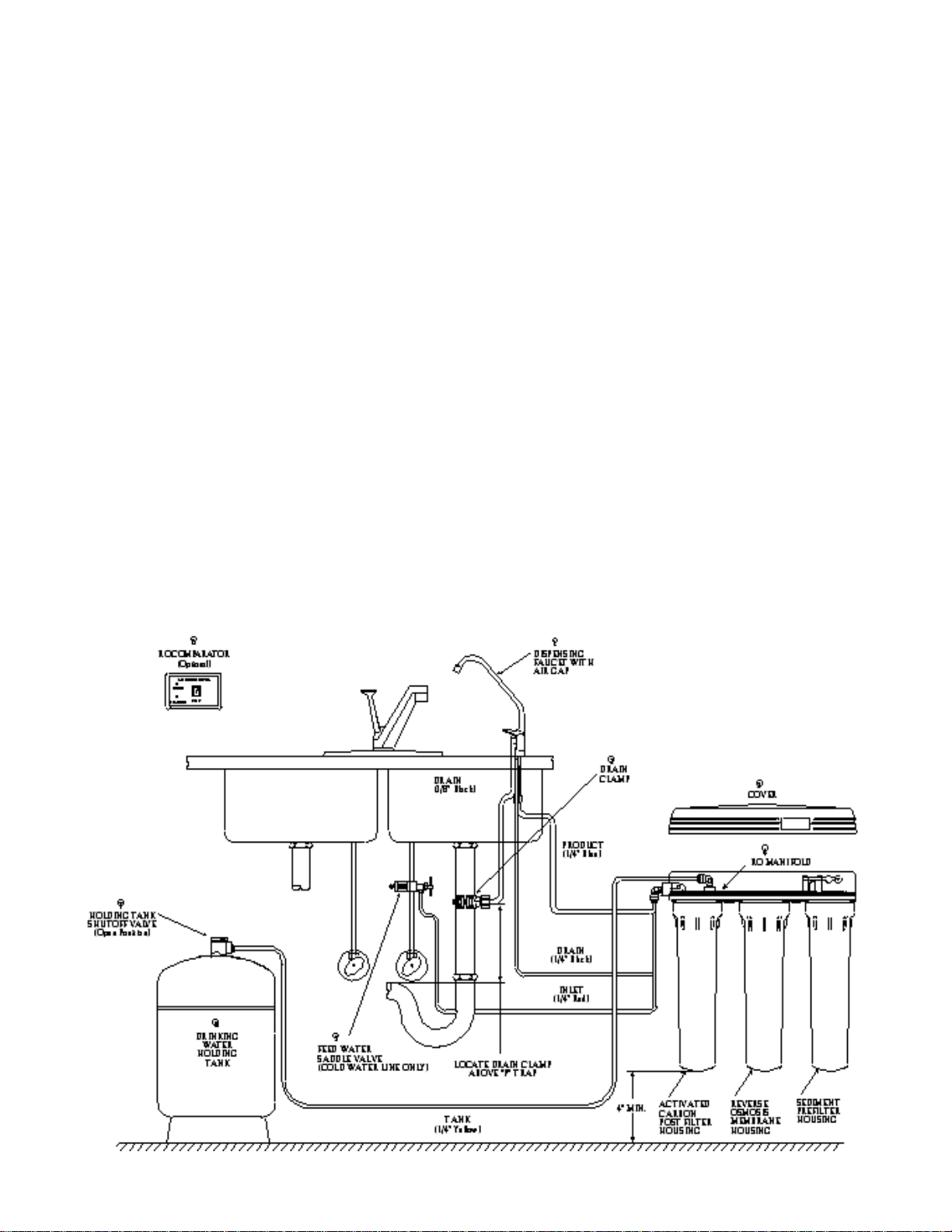
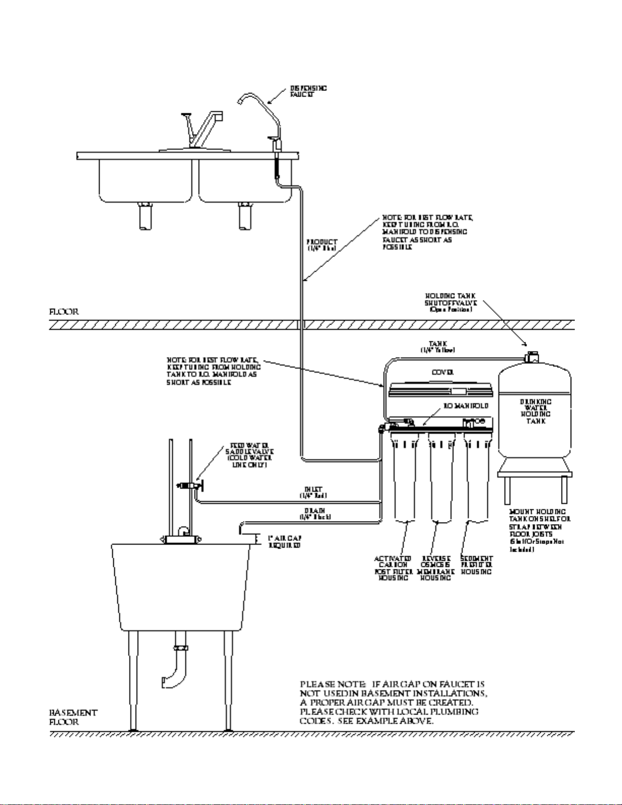
2. Locate the " Red Feed Water Tubing.
Remove the red plug from the fitting
labelled “In” on the manifold and insert the
tubing. Reference the special supplement
sheet in the carton for proper connection of
all tubing and removal of plugs. Run the
tubing along its course to the Feed Water
Saddle Valve, trim to length. (Refer to Fig.
1, page 1.)
Refer to Fig. 3, page 6. To the end of the
red polytube install the Compression Nut,
the Plastic Ferrule, and the Brass Insert.
Connect to the Feed Water Saddle Valve.
3. Locate the " Black Drain Tubing. Remove
the black plug from the fitting labelled
“Drain” on the manifold and insert the tub-
ing. Run the tubing along its course to the
" Hose Barb on the Dispensing Faucet, trim
to length and connect by firmly pressing
over the barb. Allow the tubing to relax,
then press firmly again to insure proper
seating.
4. Locate the " Blue Product Water Tubing.
Remove the blue plug from the fitting
labelled “Out” on the manifold and insert
the tubing. Run the tubing along its course
to the Dispensing Faucet and trim to length.
Push the tubing into the faucet connector.
The fitting will grab the tubing and seal it in
place. Make sure the tubing is pressed all
the way in past the O–ring to create a pres-
sure tight connection.
NOTE: If you want to pull the tubing out for
some reason, push the ring around the tub-
ing in and pull the tubing out.
5. Locate the " Yellow Tubing. Remove the
yellow plug from the fitting on top of the
manifold labelled “Tank” and insert the tub-
ing. (Refer to Fig. 1, page 1.)
6. Hang the Manifold Assembly on the mount-
ing screws and tighten. DO NOT OVER-
TIGHTEN.
E. Position the Drinking Water Holding Tank
and Make the Final Hose Connections.
1. Check the tank precharge pressure. Make
sure it is between 5 to 7 psig. If not, use a
bicycle hand pump or other pump to bring
the pressure up to the 5 to 7 psig range.
2. Pull the cap/plug off the top of the tank
where the Tank Shut–Off should go. (Refer
to Fig. 1, page 1.)
3. Wrap the white teflon tape, included in the
box, three times around the " male outlet
thread. Wrap in the direction of the threads
(clockwise, when looking down on the
Holding Tank). The tape will act as a thread
sealant. Screw on the Holding Tank
Shut–Off Valve.
4. Locate the " Yellow Tubing which is
attached to the elbow on top of the mani-
fold and run the tubing along its course to
the tank and trim to length. Insert the tubing

into the Holding Tank Shut–Off Valve fit-
ting. Make sure the tubing is pressed in all
the way past the O–ring. The fitting will
grab the tubing and seal it in place.
NOTE: If the optional RO Comparator is
used, its location and the location of its test
cells should be determined at this time.
The "In" Cell should be located in the Red
Feed Water tubing line before the R.O.
System.
The "Out" Cell should be located in the
Blue Product Water Tubing Line, between
the "Out" Port and the Dispensing Faucet.
F. Start Up
At time of start up and each time the filters
are changed the system should be sanitized
(also see Operation and Maintenance Sec. V,
B.1–4, page 10).
1. Sanitizing the system and installing the
Sediment Prefilter. Use a drip pan to aid
clean–up.
NOTE: The system should be sanitized
BEFORE installing the Activated Carbon
Post Filter or the R.O. Membrane.
• Use a good quality unscented 5 % liquid
chlorine household bleach.
• Open the Dispensing Faucet by lifting the
black handle and open the Holding Tank
Shut–Off Valve (the handle should be
parallel with the valve body).
• Remove the plug on the underside of the
manifold labelled “SEDIMENT”. Remove
the protective wrapping from the
Sediment Prefilter. Pour one capful of
bleach (this is approximately 2 tsp. or 10
ml) into one of the white Housings. Install
the Sediment Prefilter. (Install ONLY the
Sediment Prefilter at this time.)Insert a
Housing
O–ring into the Housing groove, (press
firmly in place). Engage and firmly tighten
the Housing hand tight only.
• Remove the plugs labelled “MEM-
BRANE” and “ACTIVATED CARBON”
from the underside of the manifold. To
each of the remaining white Housings,
add one capful of bleach. Insert a
Housing O–ring, engage and firmly tight-
en the Housings hand tight only.
• Slowly open the Feed Water Saddle
Valve (turning counter clockwise).
• As soon as the water begins to come out
of the Dispensing Faucet, close the
Faucet.
• Let stand for 15 minutes.
NOTE: During this time, check the sys-
tem carefully for leaks.
• At the end of 15 minutes, CLOSE the
Feed Water Saddle Valve and open the
Dispensing Faucet.
• Allow the Holding Tank to completely
drain, then remove the Activated Carbon
Filter Housing (the closest of the three to
the
In–Out Ports), empty, and install the
Activated Carbon Post Filter. Firmly tight-
en the Housing hand tight only.
2. Installing the R.O. Membrane:
• Remove the R.O. Membrane Housing,
(the middle one), and empty.
• Insert the Membrane up into the mani-
fold. (The O–rings should be up toward
the manifold.) Check the Housing O–ring
for proper position in its groove, engage
and firmly tighten the Housing hand tight
only.
3. Rinsing the system:
• Slowly open the Feed Water Saddle
Valve fully counter clockwise.
• The Holding Tank Valve should be open.
• Check the Air Gap Window on the
Dispensing Faucet to be sure that the
drain water is flowing. (Refer to Figure 2,
page 6.) The R.O. System is now making
water.
• Do not open the Faucet for at least 8
hours.
• Do not use the first three full tanks of
water.
CAUTION: The R.O. Membrane is
shipped with a preservative in it (0.5%
sodium metabisulfite). This will be rinsed
out with the first water produced. Allow
the Holding Tank to fill (overnight) and
discard the first three full tanks of produc-
tion. It takes approximately 8 hours to
make a full tank.
When the Faucet is first opened, expect
air and carbon fines (very fine black pow-
der) from the Activated Carbon Post

Filter to be rinsed out. This is normal for
the first tank of water or after the
Activated Carbon Post Filter is changed.
SECTION V. OPERATION & MAINTENANCE
A. Normal Operation
1. It is normal for the Total Dissolved Solids
(TDS) of the water to be higher than nor-
mal during the first 5 gallons of operation,
this is due to the sanitizing solution and
the new Post Filter. After this water is
rinsed to drain, the removal rate should
stabilize at a value of greater than 75%.
The optional R.O. Comparator measures
the TDS reduction and gives an indication
of proper performance.
2. R.O. systems produce drinking water at
relatively slow rates, it can take up to 8
hours or more to fill the Holding Tank.
Normal operation is to let the Holding Tank
fill with water and then draw water as
needed. When the pressure in the Holding
Tank falls to a given pressure (as the
water is being used) the Automatic Shutoff
Valve (ASO Valve) will start water produc-
tion and the system will refill the Holding
Tank. When the Holding Tank is full and
no water is being used, the ASO Valve will
automatically shut–off the feed water to
conserve water.
The more water that is used (up to the
capacity of the system) the better the R.O.
system will function. Other uses for the
water are flowers, pets and rinsing glass-
ware.
With each use it is recommended that you
turn the tap for at least 10 seconds prior to
using water. This is especially important if
the water tap has not been used daily.After
periods of non–use, such as a week of
vacation, it is better to empty the holding
tank and allow the system to produce fresh
water for use. If the system is not used for
3–4 weeks or longer, it is a good idea to
resanitize the system and to change the
Sediment Prefilter and the Activated
Carbon Post Filter.
B. Changing Filters
THIS R.O. SYSTEM CONTAINS FILTERS
WHICH MUST BE REPLACED AT REGULAR
INTERVALS TO MAINTAIN PROPER PER-
FORMANCE. USE ONLY FACTORY
APPROVED FILTERS.
The recommended interval for changing the
filters (not the R.O. Membrane) is every six (6)
months. Typical C.T.A. Membrane life
expectancy is one year. Local conditions may
dictate more frequent changes.
NOTE: If the R.O. Membrane is to be
replaced, see Sec. IV, F.1–3, page 9 for the
proper procedure.
Use a drip pan to catch any water that may
spill when the Filter Housings are removed.
Refer to Fig. 1, page 1 for component location.
1. Close the Feed Water Saddle Valve by
turning fully clockwise and open the
Dispensing Faucet by lifting the handle.
Allow the Holding Tank to empty.
2. Loosen and remove the Sediment Filter
and the Activated Carbon Filter Housings.
Discard the filters.
3. Wash the inside of the Housings using a
mild detergent and a soft cloth. Do not use
abrasive cleaners or pads. Thoroughly
rinse all soap from the Housings before
reassembly.
4. To sanitize the system and replace the fil-
ters:
NOTE: The system should be sanitized
before installing the Activated Carbon Post
Filter.
• Use a good quality unscented 5 % liquid
chlorine household bleach.
• Add one capful of bleach (this is 2 tsp. or
10 ml) to the Sediment Filter Housing.
Remove the wrapping and install the
Sediment Prefilter only. (The O–rings
should be up, toward the Manifold on all
filters.) Check the Housing O–ring for
proper position in its groove, engage and
firmly tighten the Housing hand tight only.
• Add one capful of bleach to the Activated
Carbon Filter Housing. Carefully fill the
Housing with tap water and temporarily
install the Housing without the Activated
Carbon Post Filter.
•The Dispensing Faucet should be open,
slowly open the Feed Water Saddle
Valve.
• As soon as water begins to drip out of the
Dispensing Faucet, close the Faucet.

• Let the system stand for 15 minutes.
• At the end of 15 minutes, in the following
order, close the Feed Water Saddle
Valve, close the Holding Tank Valve and
open the Dispensing Faucet to release
the pressure.
• Remove the Activated Carbon Filter
Housing and empty. Remove the wrap-
ping and install the Activated Carbon Post
Filter. Firmly tighten the Housing hand
tight only.
• Disconnect the yellow product water tub-
ing that runs from the Holding Tank to the
Manifold (see Fig. 1, page 1). Put 50
drops of bleach (this is tsp. or 3 ml) into
the tubing and reconnect it.
• Slowly open the Feed Water Saddle
Valve. When water begins dripping out of
the Dispensing Faucet, in the following
order, close the Faucet and then open the
Holding Tank Valve.
• Do not open the Faucet for at least 8
hours.
• Discard the first three full tanks of water
produced; they will contain chlorine.
• When the Faucet if first opened, expect
air and carbon fines (very fine black pow-
der), from the new Activated Carbon Post
Filter to be rinsed out. This is normal for
the first tank of water.
SECTION VI. TECHNICAL DATA
A. Water Quality
Water quality is normally measured with a
special meter that measures the water’s abili-
ty to conduct electricity. The more dissolved
solids in the water, the higher the conductivity.
The results are usually reported in Parts per
Million (ppm) or Milligrams per Liter (mg/l) of
Total Dissolved Solids (TDS). (Although
technically they are not exactly equal, in most
discussions ppm = mg/l.)
R.O. Membranes are rated by the amount of
dissolved solids that are rejected. This rating
is a ratio of the TDS in the feed water to the
TDS in the product water and is reported as
Percent Rejection. If the feed water con-
tained 100 ppm of TDS and the product water
contained 10 ppm of TDS, 90 ppm have been
rejected and the reject ratio is 90%.
Percent Rejection =
Feed TDS–Product TDS x 100%
Feed TDS
EXAMPLE: Feed water is 500 ppm TDS and
the product water is 75 ppm TDS.
Percent Rejection = 500 – 75 x 100%
500
Percent Rejection = 0.85 x 100% or 85%
B. Water Quantity
Water quantity is termed Flux or Product
Water Rate and is measured as the amount
of water produced in one day. It is reported as
Gallons per Day (gpd) or Liters per Day
(lpd).
The flow of water to drain is the Reject Water
Rate and is measured as Gallons per Day
(gpd) or as Milliliters per Minute (ml/min).
Milliliters per minute x 0.38 = gallons per day
EXAMPLE: The drain flow will fill a graduated
cylinder to the 105 ml mark in one minute.
105 ml/min. x 0.38 = 40 gpd
If the container available measures ounces,
use the following conversion:
Ounces per minute x 11.2 = gallons per day
EXAMPLE: The product flow will fill 1 ounces
in two minutes.
1.75 oz. ÷ 2 min. = 0.875 oz./min.
0.875 oz./min. x 11.2 = 9.8 gpd
The Reject Ratio is the amount of water pro
duced compared to the amount of water flow
ing to drain.
Reject Ratio = Reject Rate
Product Rate
EXAMPLE: The product rate is 10 gpd and
the reject rate is 40 gpd
Reject Ratio = 40 ÷ 10
Reject Ratio = 4 or 4–to–1
The Percent Recovery is another way to
measure the amount of water produced as
compared to the amount actually used.
% Recovery = Product Rate x 100%
Feed Rate
NOTE: The total flow or feed water rate into
the system is the sum of the product flow and
the drain flow.
EXAMPLE: The product water rate is 10 gpd

and the drain water rate is 40 gpd
Feed Rate = 10 gpd + 40 gpd = 50 gpd
% Recovery = 10 gpd x 100%
50 gpd
% Recovery = 0.20 x 100% or 20%
C. Net Pressure Differential
Most R.O. Membranes are rated at a standard-
ized condition of 77˚F (25˚C) and 65 psig
(450kPa) discharging to atmospheric pressure.
Product water quality and quantity greatly depend
upon the Net Pressure Differential (∆p)
across the R.O. Membrane. This pressure dif-
ferential is a summation of the feed water
pressure at the Membrane, which tries to push
the water through, the pressure in the Holding
Tank, which tries to push the water backwards
NOTES:
and the osmotic pressure, which also tries to
push the water backwards.
The Osmotic Pressure is in proportion to the
dissolved minerals in the water and can be ap-
proximated by 1 psig for each 100 ppm of
TDS.
EXAMPLE: A feed water with 1500 ppm of
TDS would exert a backward pressure of
about 15 psig on the membrane.
Net Pressure Differential =
Feed Water Pressure – Holding Tank
Pressure – Osmotic Pressure
The higher the net pressure differential, the
higher the quantity and quality of water pro-
duced. Some loss of production is normal
when using a pressurized Holding Tank.

D. WATER PRODUCTION RATE CHART
Estimated Water Production Rate
Feed Water in Gallons Per Day (GPD) for Line Pressure of:
Temp.(˚F) TDS*(ppm) 40 psi 50 psi 60 psi 70 psi 80 psi 90 psi
50 50 5.0 6.5 8.0 9.5 11.0 12.6
500 4.3 5.8 7.3 8.8 10.4 11.9
1000 3.5 5.0 6.6 8.1 9.6 11.1
1500 2.7 4.3 5.8 7.3 8.8 10.4
60 50 5.8 7.6 9.4 11.2 12.9 14.7
500 5.0 6.8 8.6 10.4 12.1 13.9
1000 4.1 5.9 7.7 9.5 11.2 13.0
1500 3.2 5.0 6.8 8.6 10.4 12.1
70 50 6.8 8.9 11.0 13.1 15.1 17.2
500 5.9 7.9 10.0 12.1 14.2 16.3
1000 4.8 6.9 9.0 11.1 13.2 15.3
1500 3.8 5.9 7.9 10.0 12.1 14.2
80 50 8.0 10.4 12.8 15.3 17.7 20.2
500 6.8 9.3 11.7 14.2 16.6 19.1
1000 5.6 8.1 10.5 13.0 15.4 17.9
1500 4.4 6.8 9.3 11.7 14.2 16.6
90 50 9.3 12.2 15.0 17.9 20.8 23.6
500 8.0 10.9 13.7 16.6 19.5 22.3
1000 6.6 9.5 12.3 15.2 18.0 20.9
1500 5.2 8.0 10.9 13.7 16.6 19.5
*Total Dissolved Solids (TDS) measured in Parts Per Million (ppm).
Please Note: This chart is based upon a start–up of a system when the storage tank is empty, (7psig
precharge). As the tank fills, and backpressure from the tank increases, the GPD rating will decrease.

SECTION VII. TROUBLE SHOOTING GUIDE
Problem Possible Cause Solution
Open Valve or unclog.
Replace filters.
Feed Water pressure must be above
40 psig.
See Feed Water operating limits.
Correct cause of fouling, replace
Membrane.
Empty water from Holding Tank,
and with the faucet open, adjust air
pressure to 5–7 psig (35–48 kPa) range.
Replace tank.
Open Valve.
Clear or replace Drain Restrictor.
Clear or replace the Air Gap Faucet.
Free check.
Replace ASO Valve components.
Replace Post Filter.
Empty water from Holding Tank and
with the faucet open, adjust the air
pressure to 5–7 psig (35–48 kPa) range.
Check for leakage at the Air Valve Stem.
Open Valve.
Repair or replace Dispensing Faucet.
Allow Holding Tank to refill (adding
a second Holding Tank will increase
storage capacity).
See Low Quantity of Product Water
from Holding Tank section above.
Replace Filter.
Feed Water Pressure must be above
40 psig.
Check Feed Water Saddle Valve.
Check O–ring.
Check the brine seal.
If Membrane life is unusually short,
find and correct the problem.
Replace Membrane.
Feed Water Saddle Valve is plugged or
closed.
Clogged Sediment/Carbon Prefilter or
Activated Carbon Post Filter.
Low water pressure.
R.O. Membrane is fouled.
Air precharge pressure in Holding
Tank is too high.
Air precharge is too low
Air bladder in the Holding Tank is
ruptured.
Holding Tank Valve is closed.
No drain flow, the Drain Restrictor
is plugged.
No drain flow, the drain orifice in the Air
Gap Faucet is plugged.
The Check Valve is stuck.
The ASO Valve is malfunctioning.
Activated Carbon Post Filter is plugged.
Air precharge in the Holding Tank is
too low.
Holding Tank Valve is partially closed.
The dispensing Faucet is out of
adjustment or faulty.
Heavy water use, Holding Tank is deplet-
ed.
Low Water Production.
Clogged Sediment/Carbon Prefilter.
Low Water Pressure.
R.O. Membrane O–ring is crimped.
R.O. Membrane brine seal is not sealing
up into the manifold head.
R.O. Membrane is expended.
Low quantity of Product Water
from Holding Tank
Low pressure at the Dispensing
Faucet
High Total Dissolved Solids (TDS) in
the Product Water

Correct plumbing.
Clear or replace Drain Restrictor.
Clear or replace Air Gap Faucet..
Repair or replace the ASO Valve
Components.
Flush with several full tanks of
Product Water.
An increase in Feed Water TDS will
give a corresponding increase in
Product Water TDS.
Replace Filter.
Clean, flush and sanitize the system.
Replace the filters.
Correct plumbing.
Pretreat Feed Water to remove
dissolved gasses.
See high TDS in the Product Water
section.
Empty storage tank. Wait 15 minutes
for the system to begin making water
and test water quality again.
Replace filters and/or membrane.
Clear Air Gap.
Rinse with vinegar for removal of
calcium buildup.
Clear tubing.
Align with hole in the drain pipe.
Replace Drain Restrictor.
Adjust Faucet by turning the tee bar
just below the handle to provide a
small amount of free play in handle
when shut off.
O–rings are bad, repair or replace
faucet.
O–ring is bad, replace O–ring.
O–rings are bad. Repair or replace
the faucet.
High Total Dissolved Solids (TDS)
in the Product Water
(continued)
Problem Possible Cause Solution
Tastes and odors in the Product
Water
The Product Water and Drain Water
lines are reversed.
No drain flow, Drain Restrictor is
clogged.
No drain flow, the drain orifice in
the Air Gap Faucet is plugged.
The ASO Valve is not closing.
New Activated Carbon Post Filter not
rinsed completely.
The Feed Water TDS has increased.
The Activated Carbon Post Filter is
exhausted.
There is foreign matter in the Holding
Tank.
The Product Water and Drain Water
lines are reversed.
Dissolved gasses in the Feed Water.
Increase in Product Water TDS.
System not being used for extended
period of time.
Filters are plugged or membrane is
fouled or exhaused.
Air Gap is blocked.
Drain tubing is clogged.
Drain Clamp hole is misaligned.
Excessive drain flow rate.
Leaks from spout.
Leaks from base of the delivery
tube.
Leaks from beneath the handle.
Drain Water overflows at the Air
Gap Faucet
Close the Feed Water Saddle Valve and relieve pressure before disconnecting
any tubing or replacing any fitting. Before replacing a fitting, re–cut the tubing
and re–insert into the fitting to see if that solves the leak. If pipe threads are
leaking, remove and retape with Teflon tape.
Fitting leaks in general
Faucet leaks or drips
Amber light on optional water quali-
ty monitor

1
2
3
4
5
6
7
8
9
10
11
12
13
14
17
26
19
EXPLODED VIEW & PARTS LIST
15
16
20
21
18
17
22
23
24
25

DRAWING NO. PART NO. DESCRIPTION
1 ...................... S2009 ...................................... Self Tapping Screw
2 ...................... S2005 ...................................... ASO Cap
3 ...................... S2013 ...................................... ASO Cap O–Ring
4 ...................... S2011 ...................................... ASO Diaphragm – Large
5 ...................... S2007 ...................................... ASO Piston
6 ...................... S2006 ...................................... ASO Piston Ring
7 ...................... S2010 ...................................... ASO Diaphragm – Small
8 ...................... S2028–03RS............................ Manifold Plate
9 ...................... S1276 ...................................... Check Valve
10 ...................... S1277 ...................................... Check Valve Retainer
11 ...................... S7011 ...................................... Sediment Prefilter
12 ...................... S1224RS.................................. C.T.A. R.O. Membrane 14 gpd (53 lpd)
13 ...................... S3069 ...................................... Housing O–Ring
14 ...................... S7029–09 ................................ Housing
15 ...................... S7025 ...................................... Activated Carbon Post filter
16 ...................... S2012–01 ................................ Inlet/Outlet O–ring
17 ...................... S2054 ...................................... 1/8" MPT x 1/4" Polytube Elbow
18 ...................... S2054–01 ................................ 1/8" MPT x 1/4" Polytube Drain Restrictor Elbow
19 ...................... S2016–4 .................................. Drain Restrictor 40 GPD (151 lpd) Red
20 ...................... S2004 ...................................... Inlet/Outlet Cap
21 ...................... S2009 ...................................... Self Tapping Screw
22 ...................... S1406 ...................................... 1/4" Union Elbow
23 ...................... N1033...................................... Bracket Screw
24 ...................... S2014 ...................................... Mounting Bracket
25 ...................... S3072 ...................................... Wrench for Housing
26 ...................... S1405 ...................................... 1/4"–3/8" Fitting Wrench
OTHER COMPONENTS AS SHOWN IN FIGURE 1, PAGE 1.
DRAWING NO. PART NO. DESCRIPTION
1 ...................... S1089–07 ................................ Long Reach Air Gap Faucet w/ 1/4" Connector
2 ...................... S1117–01 ................................ 3/8" Drain Clamp Assembly
3 ...................... S2019NN................................ Manifold Cover
5 ...................... S1118–01 ................................ Feed Water Saddle Valve
6 ...................... C2000...................................... RO–3 Steel Holding Tank
7 ...................... S1396 ...................................... Holding Tank Shut–Off Valve
8 ...................... R7075...................................... R.O. Comparator (optional)

Form No. S1248-09
Updated 10/98
R.O. DRINKING WATER SYSTEM
FIVE/ONE YEAR LIMITED WARRANTY
Marlo warrants its R.O. Drinking Water System to be free from defects in materials and workmanship
for a period of five years from the date of purchase when installed and operated within recommended
parameters.
Marlo will repair or replace at its discretion any defective component. This warranty does not cover the
disposable sediment and carbon filters whose service life depends on feed water conditions. The reverse
osmosis membrane is warrantied for one year. If the required prefilter conditions to the membrane are not
followed the membrane will not be warrantied.
CONDITIONS OF WARRANTY
The above warranty shall not apply to any part of the Marlo R.O. Drinking Water System that is dam-
aged because of occurrences including but not limited to neglect, misuse, alteration, accident, misapplica-
tion, physical damage, or damage caused by fire, acts of God, freezing or hot water.
All replacement filters and membranes must be Marlo filters and membranes or the
warranty is void. If the unit is altered by anyone other than Marlo the warranty is void.
To obtain warranty service: (A) contact your local dealer who supplied the unit, or (B) contact the fac-
tory for the dealer nearest you. It is the obligation of the owner to pay for shipping or travel charges to
return the defective part.
This is the sole warranty made by Marlo with respect to the R.O. Drinking Water System. No other
warranties, expressed or implied, are given including merchantability or fitness for a particular purpose,
incidental or consequential damages, or other losses.
This exclusion applies to the extent exclusion is permitted by the law.
No person or representative is authorized to assume for Marlo any liability on its behalf, or in its name,
except to refer the purchaser to this warranty.
This warranty gives you specific legal rights, you may also have other rights which vary from state to
state.
PO Box 044170 • 2227 South Street
Racine, WI 53404-7003
Phone 414/681-1300
Fax 800/681-1318
Table of contents
Other Marlo Incorporated Water System manuals
Popular Water System manuals by other brands

Culligan
Culligan Aquasential Tankless RO owner's guide

Klaran
Klaran WS Series manual

AQUAMOTION
AQUAMOTION Aqua-Flash AMH1K-3UV instruction sheet

Millipore
Millipore DIRECT-Q 3 SYSTEM user manual

Sungrabber
Sungrabber Solar Hot Water System owner's manual

Watermark
Watermark JE Series installation instructions