SAFETY WARNINGS
• To prevent short circuits, this product should only be used inside and only in dry spaces.
Do not expose the components to rain or moisture. Do not use the product close to a
bath, swimming pool etc.
• Do not expose the components of your systems to extremely high temperatures or bright
light sources.
• Do not open the product: the device contains live parts. The product should only be
repaired or serviced by a qualified repairman.
• In case of improper usage or if you have opened, altered and repaired the product
yourself, all guarantees expire. Marmitek does not accept responsibility in the case of
improper usage of the product or when the product is used for purposes other than
specified. Marmitek does not accept responsibility for additional damage other than
covered by the legal product responsibility.
• This product is not a toy. Keep out of reach of children.
• Adapters: Only connect the adapter to the mains after checking whether the mains voltage
is the same as the values on the identification tags. Never connect an adapter or power
cord when it is damaged. In that case, contact your supplier.
TABLE OF CONTENTS
INTRODUCTION ……………………………………………………………………............................................... 3
1. USE AND OPERATION OF THE MEGAVIDEO55…………………................................................ 3
2. SET CONTENTS…………………………………………………………………................................................. 4
3. CONNECTING APPLIANCES TO THE MEGAVIDEO55 MODULATOR................................ 4
4. CONNECTING THE AERIAL SIGNAL TO THE MEGAVIDEO55 MODULATOR............... 5
5. SETTING THE CHANNEL……………………………………………………................................................. 6
6. SETTING THE INFRARED RETURN CHANNEL FOR USING REMOTE CONTROL.......... 7
7. USING INFRARED RECEIVERS IN DIFFERENT ROOMS……...................................................... 8
8. FREQUENTLY ASKED QUESTIONS…………………………………….................................................. 9
9. TECHNICAL DATA…………………………………………………………….................................................. 10
INTRODUCTION
Congratulations on purchasing the MegaVideo55! The MegaVideo55 is a programmable
stereo modulator that converts audio and video signals from, for instance, your DVD player,
satellite receiver, video recorder, security camera, decoder or PC and adds it to your aerial
cable as an extra channel. Then you can receive this signal as a kind of internal TV channel
anywhere in the house where you have an aerial connection.
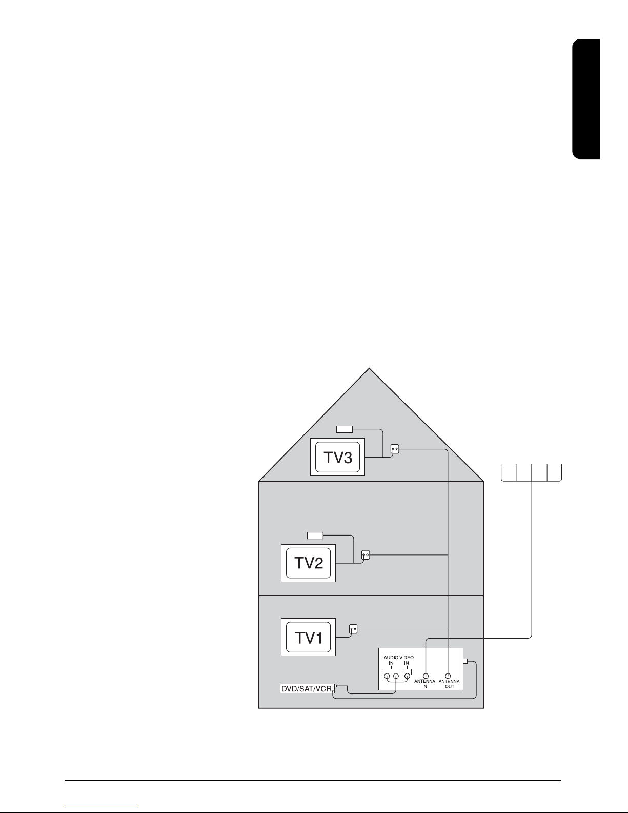
1. USE AND OPERATION OF THE MEGAVIDEO55
You could say that the modulator is “looped into” the aerial signal. The incoming aerial signal
is connected to the aerial input. The audio/video signal (from a DVD player for instance) is
3
MEGAVIDEO55TM
ENGLISH