Operation Guide for Remote Control
19
18
17
PRE-OUT
Connect the input jacks of the extension Power
amplifier or the Mixer to these jacks.
16
SPEAKER SYSTEMS
SPEAKER IMPEDANCE
System 1 : Minimum 4 Ohms.
System 2 : Minimum 4 Ohms.
System 1+2 : Minimum 8 Ohms.
14
Voltage Selector Switch
For selecting input power voltage. Please adjust
according to the local power before connect to the
AC outlet.
AC Outlets
Allows expanding power and providing power for
other device. (Maximum total 100W)
REC Audio Output Jacks
Connect to a recorder component such as a
cassette deck to record the speaker output
audio.
15
BGM Audio Input Jacks
Connect the input jacks of equipments for background
music or public channels.
* BGM INPUT LEVEL Control
Adjust this control to optimize the BGM input level.
Note: BGM volume control can only be adjusted here
and cannot be adjusted by the master volume control.
* MONO/STEREO Switch
MONO or STEREO.
CAUTION !
Please select the input power voltage rightly. Fail
of doing so could lead to malfunction or damage of
the AMP, and the AMP could be burned-out.
CAUTION !
Never use the AC OUTLETS with their maximum
ratings exceeded. Do not connect a TV monitor as
it draws a large current when power is switched
ON.
INPUT SELECT
Selection/Switch of inputted audio signals
INFRARED TRANSMIT
KEY CONTROL
UP : Press to transpose the key of music 1/4 tone UP per set.
NATURAL : Press to reset music to ORIGINAL key.
DOWN : Press to transpose the key of music 1/4 tone DOWN per set.
MIC VOLUME
Press to UP or DOWN the volume of the master microphone output.
MUSIC VOLUME
Press to UP or DOWN the volume of the master music output.
MULTIPLEX
NORMAL : General audio output and vocal performance.
PARTNER : Automatic vocal performance when there is no input to
any of the MIC connected to the MIC jacks.
MULTI : Vocal accompaniment function.
* This function is available only when the audio and video source is of
KARAOKE formate.
Terms and Functions
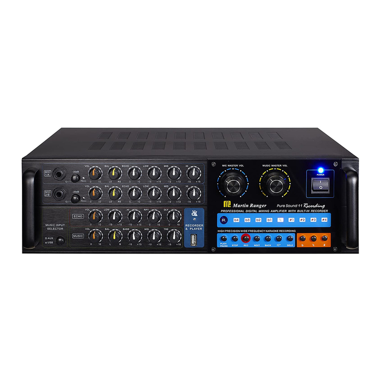
Operation Guide for Front Panel
MIC MASTER VOLUME
This knob is used for adjusting the volume of
microphones. Turn right for increasing the
volume, and left for decreasing.
3ECHO VOLUME
This knob is used for adjusting echo effect.
Turn right for boosting the effects, and left
for cuttings.
DELAY Control : Adjust the delay time.
REPEAT Control : Adjust the interval of
repetitions.
This knob is used for adjusting the volume of
music.
MUSIC VOLUME
1
2
INPUT SELECT
The location of signal - to - input can be
selected by this button. Press and hold the
button for over 4Sec. to enable or disable the
"AUTO INPUT SELECT" function.
4
KEY CONTROL
These buttons are used for adjusting the
music scale. Each step is for 1/4 tone, and
the middle button is for the original / standard
key . After changing a song, or after the
music has been terminated for more than 4
seconds, the system will automatically return
to the original key.
5
VOCAL Select
PARTNER : Automatic vocal performance when
there is no input to any of the MIC
connected to the MIC jacks.
MULTI : Vocal accompaniment function.
6
POWER
Press this switch to turn the power ON/OFF.
7
MIC INPUT ( 1 , A , 2 )
TRS 1/4" input jacks for mono or balacne microphone.
8
MIC VOL CONTROL ( 1/A , 2 )
1/A Adjusting the microphone input level of MIC 1
and MIC A.
2 Adjusting the microphone input level of MIC 2.
9
MIC TONE BASS/TREBLE
Adjusts the microphone input by boosting low
or high frequency, respectively.
10
MUSIC TONE BASS/TREBLE
Adjusts the music input by boosting low or
high frequency, respectively.
11
BALANCE
Adjusts the balance between the right and
left channel levels output from the speakers.
12
MIC Low-Cut Control
Switch the microphone input low frequency
cut.
13
14
Adjust the REVERB level. Turn right for boosting,
and left for cutting.
For specific models
REVERB LEVEL ADJ.
15
Adjust the Enhancer Hi/Low-effect level. Turn
right for boosting, and left for cutting.
ENHANCER LEVEL ADJ.
V.CANCEL
V.PARTNER
VOCAL CANCEL/PARTNER
123456
7 8 9
10 11 1213 1415
Terms and Functions
Operation Guide for Rear Panel
13
12
11
10
INPUT LEVEL-ADJ
Adjusts the music input level.
DVD Player Audio Input Jacks
Connect the audio output jacks of DVD player here.
AUX Audio Input Jacks
Connect the audio output of auxiliary component
such as a cable broadcasting tuner.
TAPE Audio Input Jacks
Connect the audio output jacks of TAPE deck here.
9ENHANCER Switch ON/OFF
ENHANCER music On/Off switch.
Video Input Jacks ( DVD , AUX , TAPE , BGV )
Receive video input from other devices.
The received signal is output through an audio
output jack according to the chosen channel.
8
4GROUND Terminal
The grounding wire shall be connected to a
grounding line to reduce the risk of electric shock.
5MIC VOL CONTROL ( 1 , A , 2 )
Microphone input , independently adjust the input
volume.
6Video Output Jacks ( 1 , 2 )
Connect to video devices such as a TV, projector,
monitor, etc. The condition of the AMP can be
easily observed through a video device.
7REAR MIC Input Jacks ( 1 , A , 2 )
TRS 1/4" input jacks for mono or balacne
microphone.
2
To household power outlet.
* Wait until connections have been completed
before connecting the power cord.
AC POWER IN
1
Control device through an external device,such as
an external IR sensor or an external control panel.
REMOTE Input Jack
3
Connect with the input / output of a micphone
effect processing component such as a graphic
equalizer.
EXIT MIC EFFECT IN/OUTPUT Jack
* An "U" type short connect is set for default.
* DVD SENSITIVITY Switch
This switch sets the sensitivity level at which the
systems auto-selector detects a DVD signal and
auto-changes it as the current input channel. Set to
LOW if other channels do not auto-enable properly.
Set to MIDDLE for standard use. Set to HIGH if
unwarranted auto-selection change occur.
* AUX SENSITIVITY Switch
This switch sets the sensitivity level at which the
systems auto-selector detects a AUX signal and
auto-changes it as the current input channel. Set to
LOW if other channels do not auto-enable properly.
Set to MIDDLE for standard use. Set to HIGH if
unwarranted auto-selection change occur.
* TAPE SENSITIVITY Switch
This switch sets the sensitivity level at which the
systems auto-selector detects a TAPE signal and
auto-changes it as the current input channel. Set to
LOW if other channels do not auto-enable properly.
Set to MIDDLE for standard use. Set to HIGH if
unwarranted auto-selection change occur.
67 4 1358
191814
9 2
10 11 12 13 15 16 17
