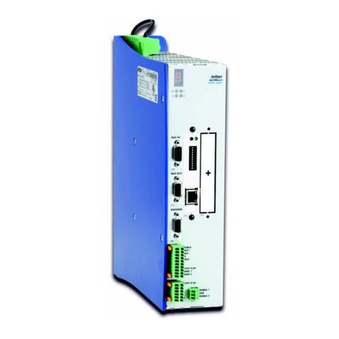
Jetter JM-1008 User manual

Original Operating Instructions
JM-1008 Servo Amplifier
We automate your success

Jetter AG
Graeterstraße 2
71642 Ludwigsburg
Phone
Switchboard +49 7141 2550-0
Sales +49 7141 2550-531
Tecnical Hotline +49 7141 2550-444
E-mail
Tecnical Hotline [email protected]
Sales [email protected]
This document has been compiled by Jetter AG with due diligence, and based on the known state
of the art. Revisions and further development of our products are not automatically mentioned in a
reviewed document. Jetter AG shall not be liable for errors in form or content, or for missing up-
dates, as well as for damages or disadvantages resulting from such failure.
Revision 1.00.1
Date of issue 6/8/2017

Jetter AG Table of contents
JM-1008 user manual iii
Table of contents
1 General information ........................................................................................................................5
1.1 Documentation ........................................................................................................................5
1.2 Acronyms used in this document ............................................................................................5
1.3 Scope of delivery and accessories..........................................................................................5
2 Safety ...............................................................................................................................................6
2.1 Warnings used in this document .............................................................................................6
2.2 General Safety instructions .....................................................................................................6
2.3 Protection against hazards......................................................................................................7
3 Purpose............................................................................................................................................8
3.1 Intended conditions of use ......................................................................................................8
3.2 Usage other than intended ...................................................................................................... 8
4 Product description ........................................................................................................................9
4.1 Nameplate ...............................................................................................................................9
4.2 Type key................................................................................................................................10
4.3 System overview ...................................................................................................................11
5 Technical specifications...............................................................................................................12
5.1 Dimensions............................................................................................................................12
5.2 Enclosure properties and operating conditions ..................................................................... 12
5.3 Environmental conditions - Storage and shipment................................................................ 13
5.4 Electrical data........................................................................................................................13
5.5 I/O interface X10 ...................................................................................................................13
5.6 Position encoder connector...................................................................................................14
5.7 Fieldbus interfaces ................................................................................................................15
6 Mechanical installation.................................................................................................................16
7 Electrical installation ....................................................................................................................17
7.1 General remarks....................................................................................................................17
7.1.1 Electromagnetic compatibility....................................................................................17
7.1.1.1 EMC requirements ....................................................................................................17
7.2 Block diagram........................................................................................................................18
7.3 Pin assignment of connections..............................................................................................19
7.3.1 Power and motor connector X1.................................................................................19
7.3.2 I/O interface X10 .......................................................................................................19
7.3.3 Encoder X61/X62 ......................................................................................................20
7.3.4 Fieldbus interfaces X18 / X19 ...................................................................................21
7.3.4.1 Fieldbus interface ......................................................................................................21
7.3.4.2 DIP switch .................................................................................................................23
Table of contents Jetter AG
iv JM-1008 user manual
7.3.4.3 EtherCAT ports X18/X19...........................................................................................23
7.4 Service interfaces..................................................................................................................23
7.5 LED display - I/O interface ....................................................................................................23
8 Maintenance and repairs ..............................................................................................................25
8.1 Maintenance..........................................................................................................................25
8.2 Repairs ..................................................................................................................................25
8.3 Replacing the servo amplifier ................................................................................................ 25
8.4 Disposal of obsolete equipment ............................................................................................25
9 Service ...........................................................................................................................................26
9.1 Operating system ..................................................................................................................26
9.2 Customer service ..................................................................................................................26

Jetter AG General information | 1
JM-1008 user manual 5 / 28
1 General information
1.1 Documentation
This installation manual contains information on how to mount, install, com-
mission, use the device in accordance with its intended purpose, service, and
de-commission the device in a drive system.
For further information refer to the following information products:
– Description of safety function STO
– JetSym Online Help
These documents must be available to all persons involved in handling or op-
erating this system or its components. These persons must observe the rele-
vant safety information.
1.2 Acronyms used in this document
BLDC Brushless DC motor
EMC Electromagnetic compatibility
PE Protective Earth
PELV Protective Extra Low Voltage
SELV Safety Extra Low Voltage
SM Stepper motor
UZK DC link voltage
1.3 Scope of delivery and accessories
The following items are included in the scope of delivery:
– Servo amplifier, mating connector for power and motor connector (X1),
and I/O interface (X10) included
Not included in the scope of delivery:
– D-Sub, and RJ45 mating connectors, as well as SD card, power lead,
and ballast resistor.
Hint Further accessories can be purchased from Jetter AG.

2 | Safety Jetter AG
6 / 28 JM-1008 user manual
2 Safety
At the time of placing on the market, this product corresponds to the current
state of the art and meets the recognized safety rules.
Besides the user manual, the rules and regulations in the operator’s country
are relevant to the operation of the product. These rules are defined by laws,
regulations, accident prevention regulations, and safety rules.
The operating voltage of this device is classified as SELV (Safety Extra Low
Voltage) and is therefore not subject to the EU Low Voltage Directive.
The operator is responsible for complying with the duties mentioned below:
– Applicable legislation, rules, and regulations
– Relevant accident prevention regulations
– Accepted safety rules
– EU directives and other country-specific regulations
2.1 Warnings used in this document
DANGER High risk
Indicates an imminently hazardous situation which, if not avoided, will result in
death or serious injury.
WARNING Medium risk
Indicates a potentially hazardous situation which, if not avoided, could result
in death or serious injury.
CAUTION Low risk
Indicates a hazardous situation, which if not avoided, could result in minor or
moderate injury.
NOTICE Material damage
Indicates a situation, which if not avoided, could result in malfunctions or ma-
terial damage.
2.2 General Safety instructions
Development of heat This device heats up in operation. To avoid burns or damages due to heat, in-
stall the device in a location that offers adequate protection. Safeguard the de-
vice against contact and make sure that there is sufficient airflow to cool the
device.
Shipment and pack-
aging
The device contains electrostatically sensitive components which can be dam-
aged if not handled properly. Damages to the device may impair its reliability.
To protect the device from impact or shock, it must be shipped in its original
packaging or in an appropriate protective packaging.
In case of damaged packaging inspect the device for any visible damage, and
inform your freight forwarder and Jetter AG of the damage caused during ship-
ment.
If the device is damaged or has been dropped, it is strictly forbidden to use it.
Storage When storing the device observe the environmental conditions given in chap-
ter “Technical specifications”.

Jetter AG Safety | 2
JM-1008 user manual 7 / 28
Modifications and al-
terations to the de-
vice
Modifications and alterations to the device and its functions are not allowed. In
the case of modifications to the device, any liability is excluded.
The original parts are specifically designed for the device. Parts and equip-
ment from other manufacturers must, therefore, not be used.
Any liability for any damages resulting from the use of non-original parts and
equipment is excluded.
Target groups Only competent and skilled personnel is allowed to commission and operate
this device. This document is intended for competent and skilled users.
During the whole product life cycle, safe handling and operation of the device
must be ensured. In the case of missing or inadequate technical knowledge or
knowledge of this document any liability is excluded.
Maintenance This device is maintenance-free.
Therefore, for the operation of the device no inspection or maintenance are re-
quired.
Repairs Defective components could cause dangerous malfunctions and could com-
promise safety.
Only the manufacturer is allowed to repair the device.
Do not open the device!
Disposal of obsolete
equipment
The device must be disposed of in accordance with the Environmental Product
Declaration EPD. Applicable local environmental directives and regulations
must be complied with. This product must be disposed of as waste electronic
equipment. Waste packaging material must be recycled or reused.
2.3 Protection against hazards
DANGER Hazardous axis movements
Axis movements and fast accelerations cause high mechanical forces.
● Keep out of the danger zone of the machine.
● Do not disable any safety equipment.
● Have malfunctions eliminated by qualifed personnel.
DANGER Electric shock
High voltage caused by wrong connection.
● Mind the relevant safety regulations.
WARNING Electromagnetic fields
Health hazard for persons with heart pacemakers, metal implants and hearing
aids caused by electromagnetic signals.

3 | Purpose Jetter AG
8 / 28 JM-1008 user manual
3 Purpose
3.1 Intended conditions of use
This servo amplifier is intended for installation in electrical systems or ma-
chines. It may only be commissioned as an integrated component of such a
system or machine.
Connect only electric motors and encoders to this device. Operate the device
only in accordance with the intended conditions of use, and within the limits
set forth in the technical specifications. Operate the servo amplifier only in a
closed control cabinet. The specified installation conditions must be complied
with.
This servo amplifier is a product which can be used in drive systems of cate-
gory C2 (industrial environment) according to EN 61800-3. To this end, the de-
sign of the system must be EMC-compliant.
Usage as agreed upon includes operation in accordance with this manual.
3.2 Usage other than intended
Do not operate the device under conditions exceeding the technical specifica-
tions given in this manual and application examples. Noncompliance with the
safety information is regarded as “usage other than intended”.
The device must not be operated under operating conditions that differ from
the specified ambient conditions.
If the device is used in any way other than intended, Jetter AG shall assume
no liability.

Jetter AG Product description | 4
JM-1008 user manual 9 / 28
4 Product description
4
3
2
1
8
9
7
6
5
Fig.1: Connections
1Encoder connector
X61 2Power and
motor connector X1
3 SD card X22 4 DIP switch S2
5 Address selector S1, optional 6 Fieldbus interface IN X18
7 Fieldbus interface OUT X19 8 I/O interface X10
9 Encoder connector X62 10
4.1 Nameplate
1*24VDC / 0,3A
1*24-48VDC / 10A
JM-1008-S1A0
Enclosure Rating: IP20
Made in GermanyAmbient Temperature: 0 - 40°C, 32 - 104°F
3*17-34VAC / 0-400Hz / 3*8A
60881662_00
Vx.xxxx
20993548XXXXXX
Out:
Logic Supply:
Power Supply:
SN:
Part No:
1
2
4
3
9
8
7
6
5
Fig.2: Nameplate of the servo amplifier
1 Nameplate 2 Control voltage
3 Output values 4 Bar code
5 Ambient temperature 6 Enclosure IP class
7 Serial number 8 Part number
9 Power connection

4 | Product description Jetter AG
10 / 28 JM-1008 user manual
Serial number
The serial number consists of the following elements:
YY Year of manufacture
WW Week of manufacture
127590 Production-specific code
XXXX 4 digit consecutive device number,
devices produced in this week/year
4.2 Type key
The type key consists of the following elements:

Jetter AG Product description | 4
JM-1008 user manual 11 / 28
4.3 System overview
MM
M
Jetter AG
Jetter AG
Jetter AG
JM100X JM100X JM100X
2
1
3
X1
X10
4
5
6
Fig.3: Drive system - Overview
1 PELV/SELV 24 V DC 2 PELV/SELV 12 V … 48 V DC
3 Controllers 4 Bus interfaces
5 Servo amplifiers 6 Motor with encoder

5 | Technical specifications Jetter AG
12 / 28 JM-1008 user manual
5 Technical specifications
5.1 Dimensions
Fig.4: Dimensions
5.2 Enclosure properties and operating conditions
Enclosure
Material Galvanized steel plate
Degree of protection IP20
Allowed pollution Pollution degree 2 to EN 61800-5-1
(To avoid conductive pollution, the de-
vice must be installed in a control cabi-
net to IP54)
Mechanical installation Screwed to a conductive and
grounded mounting panel
Total weight 0.41 kg
Operating conditions
Mounting orientation Vertical
Power and motor connector X1 must
point downwards
Clearance ≥ 25 mm above, below, and sidewards
Cooling Natural convection
Max. installation altitude 1000 m above sea level
Installation altitude > 1000 m on re-
quest

Jetter AG Technical specifications | 5
JM-1008 user manual 13 / 28
Operating conditions
Ambient temperature in operation 0 °C … +40 °C
Relative humidity 5 % … 85 %, non-condensing
5.3 Environmental conditions - Storage and shipment
Transport conditions
Ambient temperature - 25 °C … +70 °C
Air humidity 5 % … 95 %, non-condensing
Mechanical conditions 2M2 EN
60721-3-2:1997
Storage conditions
Ambient temperature - 25 °C … +55 °C
Air humidity 5 % … 95 %, non-condensing
Maximum storage period 1 year without restrictions
5.4 Electrical data
Control voltage
Port X10:1, X10:2
Input voltage 24 V DC (-15 % … +20 %)
SELV or PELV
Input current 300 mA at 24 V
Motor power supply
Connector X1:6, X1:7
Input voltage 24 … 48 V DC
System-independent protective mea-
sures
SELV or PELV
Regeneration Up to 60 V DC
Max. input current 10 A
DC link capacitance 470 µF
Motor connection
Connector X1:1 to X1:4
Output voltage 4 x 0 … 34 V AC
Output frequency 0…400Hz
Output current 8 A
Peak current 16 A for 8 s max.
Ballast resistor > 3 Ω
5.5 I/O interface X10
Motor holding brake
Connector X10:3, X10:4
Max. output current 500 mA
SI inputs and digital 24 V inputs
Input voltage Min. Typ. Max.
ON +15 V +24 V +30 V
OFF -3 V 0 V +5 V
Input current 5 mA
Cable length 30m max.

5 | Technical specifications Jetter AG
14 / 28 JM-1008 user manual
Analog inputs
Connector X10:16, X10:20
Voltage range -10 V… 10 V
Design Differential inputs
Resolution 12 bits
Sampling interval 1 ms
STO checkback contact
Connector X10:9, X10:10
Design PhotoMos relay (NO contact)
Rated current < 100 mA (not short-circuit-proof)
5.6 Position encoder connector
Properties
D-Sub connector (male) Metal or ABS, metalized, IP20;
with locking screw M3
Cable type Twisted in pairs
Core cross-section According to the instructions given by
the encoder manufacturer
Shielding connection Shield connected to enclosure of drive
module via metalized D-Sub connec-
tor.
Max. cable length The manufacturer’s instructions must
be follow
(up to 100 m possible)
Resolver X61
Suitable resolvers Two-phase resolvers
Transmission ratio 0.5
Reference frequency 8 kHz
Resolution 12 bits
Max. speed 6000 min-1
HIPERFACE DSL® X61
Suitable encoders No restrictions
Sine/cosine encoder X62
Suitable encoders With or without reference signal
Voltage supply 5 V
Voltage level 1 Vss
Max. frequency: 100 kHz
Incremental encoder X62
Suitable encoders 5 V differential signals (RS-422) with
or without reference signal
Max. frequency: 500 kHz
Digital Hall sensors X62
Suitable encoders No restrictions
EnDat 2.2
Suitable encoders No restrictions
Motor temperature monitoring
Digital sensors Thermal circuit-breaker, PTC

Jetter AG Technical specifications | 5
JM-1008 user manual 15 / 28
Motor temperature monitoring
Analog Sensors KTY83-110, KTY84, PT1000
Max. cable length For some types ≤ 1m
The manufacturer’s instructions must
be followed
5.7 Fieldbus interfaces
The servo amplifier features either a CAN port, or an EtherCAT port. Detailed
information can be seen from the type key.
CAN port X18/X19:
Port type RJ45 female connector with LED
Network topology Line terminated at both ends
Connections Galvanically isolated
Connecting cable CAT5 Ethernet cable
Max. cable length 30 m (depending on the bit rate)
Bit rate 1 MBit/s
Communications profile CANopen DS301 with application pro-
file DSP402
EtherCAT port X18/X19:
Port type RJ45 female connector with LED
Network topology No restrictions (e.g. line, ring)
Connecting cable CAT5e STP or FTP Ethernet cable
Max. cable length 100 m between two nodes

6 | Mechanical installation Jetter AG
16 / 28 JM-1008 user manual
6 Mechanical installation
This servo amplifier has been designed for being installed in a control cabinet.
Die Schutzart ist IP20. The specified ambient conditions during operation must
be complied with.
The servo amplifier must be fastened to a metal mounting panel in vertical di-
rection with the power and motor connector X1 pointing downwards. Its rear
panel must have full contact with the mounting panel.
-Prior to installing the servo amplifier, check it for transport damages.
-The mounting plate in the control cabinet must not be coated.
-Make sure that the clearance around the device meets the specification.
1 Drill the mounting holes.
2 Screw the fastening bolts into the mounting panel by half of their length.
3 By means of the keyholes in the rear panel, hang up servo amplifier by the
fastening screws.
4 Screw the lower screw down tightly.
5 Screw the upper screw down tightly.

Jetter AG Electrical installation | 7
JM-1008 user manual 17 / 28
7 Electrical installation
7.1 General remarks
The user is responsible for ensuring that the installation of servo amplifier
JM-100x, motor, and other devices complies with the safety instructions (e. g.
DIN, VDE), as well as with all other relevant federal or local regulations as to
dimensioning of conductors, protection, grounding, breakers, overcurrent pro-
tection, etc.
Only qualified personnel who have completed an electrotechnical education,
and who are familiar with the documentation and the warnings and precau-
tions given therein.
Damaged products must not be installed.
The allowed input voltage range of the servo amplifier must not be exceeded.
The rated voltage of the connected motors must be higher than, or at least
equal to, the supply voltage (X1).
7.1.1 Electromagnetic compatibility
To avoid electromagnetic interferences, great attention must be paid to the in-
stallation and wiring of digital servo amplifiers. This is particularly true for
ground potential connections and shieldings.
EMC can be split into two categories:
– Immunity to interference (interferences from external sources)
– Emitted interference (interferences emitted from the devices)
Root cause for emitting interferences
The output stage of the servo amplifier features a high-speed semiconductor
switch triggered by pulse-width modulation. This is necessary to be able to
generate a variable current and a variable frequency for motor control. The
high clock rate and the steep voltage rise caused by the switching output
stage result in unavoidable emitted interferences.
Emitted interferences strongly depend on the following factors:
– Installation location
– Wiring and installation
– Additional components (line filter, line reactor, ...)
– Combination of servo amplifiers for a machine or system
7.1.1.1 EMC requirements
Standards relevant to this device
This servo amplifier is a product which can be used in drive systems of cate-
gory C2 (industrial environment) according to EN 61800-3.
EU standards and legislation
At EU level (in all member states of the European Union), standards are im-
plemented into national laws. EMC regulations are governed by EU Directive
2014/30/EC.

7 | Electrical installation Jetter AG
18 / 28 JM-1008 user manual
7.2 Block diagram
JM-100x
Digital input 1 (reference switch)
X10:1
X10:11
Motor (X1)
JM-100x_Anschlussplan_0-2_EN.vsd
STO_REL2
EtherCAT® or CAN
X18
X21
USB port
X9
SD card
Logic supply (X10)
SELV or
PELV X10:2
Power supply for logic
circuitry: +24 V
X1:6
Power supply (X1)
SELV or
PELV X1:7
48 V DC+
48 V GND
Power supply for logic
circuitry - GND
X1:5
PE
Central earthing
position -
mounting plate
(UZK)
X1:1
X1:2
X1:3
X1:4
U
V
W
Ballast
resistor
Ballast
Digital input 2 (positive limit switch)
Digital
inputs
(X10:11
through
X10:15)
Digital input 3 (negative limit switch)
Digital input 4 (touch test)
D_GND
X10:12
X10:13
X10:14
X10:16
X10:15
Analog
inputs
(X10:16
through
X10:20)
A_GND
X10:17
X10:18
X10:19
X10:20
Analog input 1 +
Analog input 1 -
Analog input 2 +
Analog input 2 -
M
X1:5
PE
Motor holding brake
(X10:3, X10:4)
X10:3
X10:4
Brake -
Brake +
BUS IN
BUS OUTX19
Service interfaces
(no user access!)
RS232 port
X20
X10:10
STO_REL1
X10:9
X10:5 STO1
X10:6 GND_STO1
SI inputs
(STO)
and feedback
(X10:4 through
X10:10)
X10:7 STO2
X10:8 GND_STO2
Position encoder
connection
(X61, X62)
Position
encoder
X61
X62
Resolver
Fig.5: Block diagram_JM-100X

Jetter AG Electrical installation | 7
JM-1008 user manual 19 / 28
7.3 Pin assignment of connections
7.3.1 Power and motor connector X1
PIN Signal Function
X1:1 U Motor connection
X1:2 V Motor connection
X1:3 W Motor connection
X1:4 Ballast Motor connection or
ballast resistor to be connected between this ter-
minal and 48 V GND
X1:5 PE Protective earth cable connection
X1:6 48 V DC Motor power supply independent of motor type
X1:7 48 V GND
PIN Signal Motor type
Servo motor DC motor with
brushes
LinMot
BLDC Low-rating linear
motors
3-phase stepper
motor
2-phase stepper
motor
X1:1 U U U+ U+
X1:2 V V U- U-
X1:3 W W n. c. V+
X1:4 Ballast Ballast Ballast V-
X1:5 PE Protective earth cable connection
X1:6 48 V DC Motor power supply independent of motor type
X1:7 48 V GND
7.3.2 I/O interface X10
1
2
3
4
5
6
7
8
2
4
6
8
10
12
14
16
18
20
1
19
Fig.6: I/O connector X10
The I/O interface includes the following pins: Power supply for logic circuitry,
motor holding brake, 2 SI inputs, 1 checkback contact, 4 digital 24 V inputs
(not SI), and 2 analog inputs.
For more information on how to connect individual inputs or outputs refer to
the connection diagram.
PIN Signal Pin Signal
X10:1 Power supply for logic cir-
cuitry +24 V X10:2 Power supply for logic cir-
cuitry GND
X10:3 Motor holding brake - X10:4 Motor holding brake +
X10:5 STO1 X10:6 GND_STO1
X10:7 STO2 X10:8 GND_STO2
X10:9 STO_REL1 X10:10 STO_REL2
X10:11 Digital input 1
(pos. limit switch) X10:12 Digital input 2
(neg. limit switch)
X10:13 Digital input 3
(reference switch) X10:14 Digital input 4
(touch probe)
X10:15 A_GND X10:16 D_GND
X10:17 Analog input 1+ X10:18 Analog input 2+
X10:19 Analog input 1- X10:20 Analog input 2-

7 | Electrical installation Jetter AG
20 / 28 JM-1008 user manual
7.3.3 Encoder X61/X62
Der Servoverstärker unterstützt den Anschluss eines Motorlagegebers an X61
oder X62. A second encoder which is directly fitted to the mechanical system
can be used to detect its position.
The following combinations are supported:
Motor encoder Second encoder
Resolver No encoder
Sine/cosine incremental encoder
Incremental encoder RS-422
EnDat 2.2 (digital)
HIPERFACE DSL® No encoder
Sine/cosine incremental encoder
Incremental encoder R-422
EnDat 2.2 (digital) No encoder
Sine/cosine incremental encoder
Incremental encoder RS-422
Sine/cosine incremental encoder No encoder
Incremental encoder R-422 No encoder
LinMot (is in preparation) No encoder
X61 Supports the following devices:
– Resolver (optional, not with option TD)
– Motor temperature monitoring
– HIPERFACE DSL® (optional, only with option TD)
Fig.7: Pinout of the X61
Resolver
PIN Signal Pin Signal
X61:1 Ref+ R1 (exciter winding+) X61:2 Sine+
X61:3 Cosine- X61:4 TH+ motor temperature
monitoring
X61:5 n. c. X61:6 Ref- R1 (exciter winding)
X61:7 Sine-X61:8 Cosine+
X61:9 TH- motor temperature monitoring
DSL HIPERFACE®
PIN Signal Pin Signal
X61:1 n. c. X61:2 n. c.
X61:3 DSL+ X61:4 TH+ motor temperature
monitoring
X61:5 n. c. X61:6 n. c.
X61:7 n. c. X61:8 DSL -
X61:9 TH- motor temperature monitoring
Table of contents
Other Jetter Amplifier manuals

Jetter
Jetter JM-208-480-OEM User manual

Jetter
Jetter JM-203B-230 User manual

Jetter
Jetter JM-108 User manual

Jetter
Jetter JM-206-230 User manual

Jetter
Jetter JetMove JM-100 S1 Series User manual

Jetter
Jetter JetMove 225-480 User manual

Jetter
Jetter JetMove 3000 User manual

Jetter
Jetter JM-35 S1 Series User manual

Jetter
Jetter JM-204-480 User manual

Jetter
Jetter JetMove D203 User manual