Specication
GCLAMP/F
Fused Drummond G Clamp
ELECTRICAL SPECIFICATIONS
Applied electrical contact force: 40N +/- 5N
Maximum working voltage: 600V AC
Maximum working current: 10A
GENERAL SPECIFICATIONS
Temperature & Humidity:
Operating: -15°C to 60°C ≤80% R.H.
Storage: -15°C to 60°C ≤80% R.H.
Altitude: up to 2000m
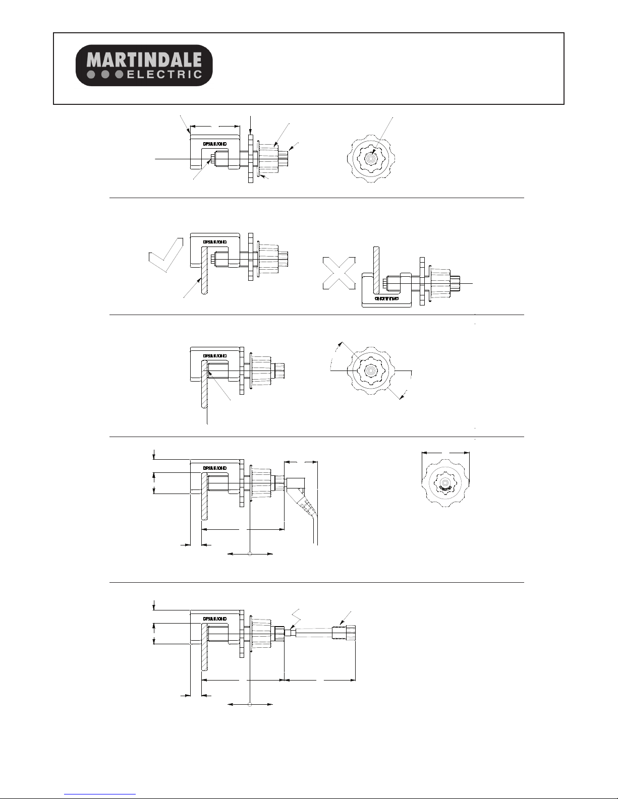
Dimensions
Length behind bus bar: 12mm
Length in front of bus bar: 87mm (+ 35mm as minimum
allowance for 4mm plug)
Height above top of bus bar: 14mm
Width: 50mm for locking ring nut
Clearance: Required to withdraw fuse holder 75mm
Bus bar
Suitable for rectangular bus bar ONLY. Not suitable for round
conductor.
Minimum Bar width: 20mm
Minimum bar thickness: 4mm
Maximum bar thickness: 26mm
Materials
Nylon 66, reinforced with 13% glass fibre.
Flammability: V2
Brass contact pin
Safety
Conforms to BS EN61010
Installation Overvoltage Rating CAT IV 600V
Pollution Degree: 2
IP rating: IP40
Fuse: 6.35 x 32mm 600V 0.5A HBC
For enhanced safety, the fuse is fully recessed inside the fuse
holder until the fuse holder is withdrawn.
RISK ASSESSMENT IS REQUIRED BEFORE
INSTALLATION.
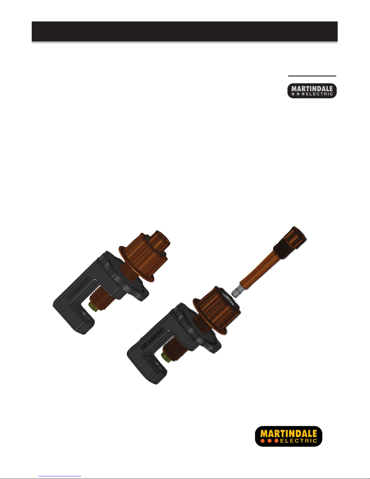
The Drummond G Clamp makes connecting to bus bars straight
forward. The clamp-on design eliminates the need to drill bus
bars and makes for a much safer reliable connection via a
standard 4 mm socket.
Ideal for connecting power monitoring and measuring equipment,
the new colour coded clamps make phase identification easy.
The insulated materials reduce the hazard to the operator and
the spring loaded contact pin and locking ring ensure reliable
results throughout extended logging periods.
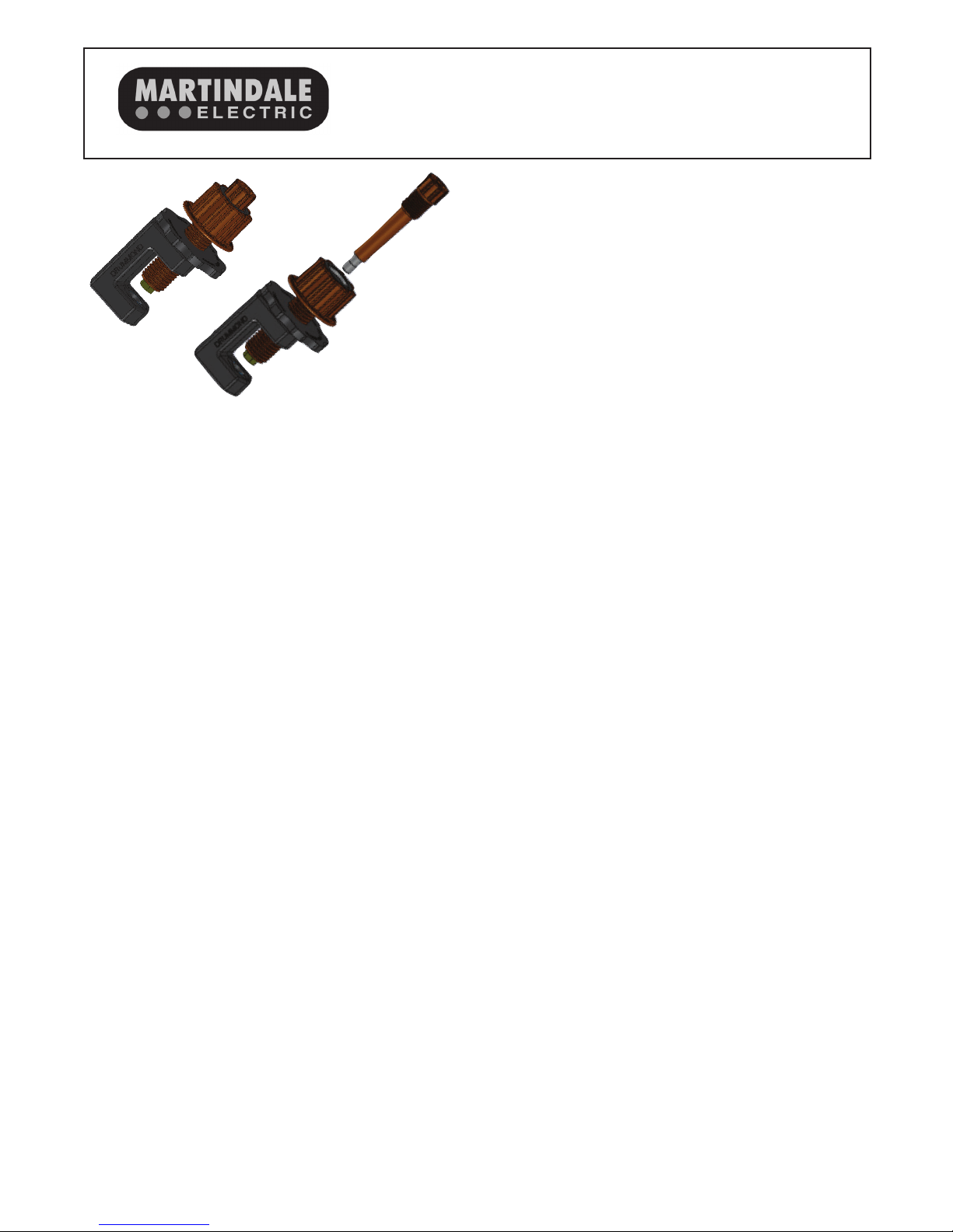
The G Clamp can be tightened by hand when wearing PPE
gloves, eliminating the need to use tools in the bus bar chamber.
They are available in Brown, Black and Grey. The standard
fused version is supplied with a replaceable 0.5A fuse within the
clamping screw providing protection at the source. Other fuse
ratings are available on request.
Available individually and in 3 phase connection kit sets including
a blue unfused G clamp for the neutral connection which requires
25mm less clearance in front of the bus bar.
Individual G clamps
DRUGCLAMP/F0.5/BK (Fused 0.5A Black)
DRUGCLAMP/F0.5/BR (Fused 0.5A Brown)
DRUGCLAMP/F0.5/GY (Fused 0.5A Grey)
DRUGCLAMP/BL (Unfused Blue)
Connection Kit 1
GCK/F/KIT1
Set of four G Clamps, black, brown, grey fused and blue unfused.
Connection Kit 2
GCK/F/KIT2
Set of four G clamps black, brown, grey fused and blue unfused
with 4m heavy duty colour coded CATIV test leads. The leads are
terminated with 45 degree 4mm safety plugs at both ends.
Due to policy of continuous development, Martindale Electric reserves the right to alter equipment specication and description outlined in this document without prior notice. No part of this
document shall be deemed to be part of any contract for the equipment unless specically referred to as an inclusion within such contract. © 2012 Martindale Electric Co. Ltd.
Martindale Electric Company Ltd.
Metrohm House, Imperial Park, Imperial Way, Watford, Hertfordshire, WD24 4PP, UK
Tel: 01923 441717 Fax: 01923 446900