Marus Nustar 1700 SII Series User manual

OWNER’S MANUAL
Hydraulic Chairs
11727 Fruehauf Drive
Charlotte, NC 28273 USA
800-304-5332
Nustar 1700 SII Series
Narrow Back Wide Back

Printed in the U.S.A.
Technical Support
Tech Support: 800-304-5332
FAX: 888-861-9366
Website: www.marus.com
31064 • Rev. 00 • 02/04/14
Warranty Statement
All of our products sold to and installed by dealers are guaranteed to be free from defects in workmanship
and materials for ve years from date of purchase. Upholstery is warranted for a period of one year from the
date of purchase. During that period, we will replace any defective part at no charge. Marus WILL NOT be
responsible for dealer or service company labor charges or shipping charges to the Marus factory.
This guarantee does not cover normal wear, stains, cuts or scratches of upholstery or surface nishes or
parts sold to OEM customers.
Staining, discoloration or deterioration of the equipment caused by disinfectant solutions is not covered
under the warranty.
Marus will pay the return freight charges from the factory to the dealer. This guarantee does not cover
damage resulting from improper installation, misuse or accidents incurred in shipping and handling.
All claims against the freight carrier must be initiated at the time the damaged items are received. The claim
is the responsibility of the customer.
We are constantly striving to improve our products. We reserve the right to make modications without the
need for prior notication and are not obliged to modify previously manufactured items.
Fiber optic system note: Units equipped with the optional ber optic system are covered under the Marus
ve year warranty, although the bulbs are items not covered under warranty and must be purchased.
It is the user’s responsibility to read and understand the contents of this manual. This
manual contains important information relative to hazards to personnel and property if
this equipment is not installed, used and/or maintained as instructed.

TABLE OF CONTENTS
General Information................................................................................................................................2
Denitions of Symbols .....................................................................................................................2
IEC Symbols ....................................................................................................................................2
Equipment Disposal .........................................................................................................................2
Incompatible Equipment .................................................................................................................2
Obtaining Technical Literature..........................................................................................................2
Interference with Electromedical Devices ........................................................................................2
Electrical Specications ...................................................................................................................2
Safety Information ..................................................................................................................................3
Storage Conditions ..........................................................................................................................3
Regulatory Information ...........................................................................................................................4
Technical Description .......................................................................................................................4
Device Classication........................................................................................................................4
Safety and Identication Markings...................................................................................................4
Cleaning, Disinfecting & Sterilization......................................................................................................5
Barrier Technique .............................................................................................................................5
Chemical Disinfection ......................................................................................................................5
Unacceptable Disinfectants .............................................................................................................5
Conditionally Acceptable Disinfectants ............................................................................................5
Cleaning Upholstery ...............................................................................................................................6
Light Soiling .....................................................................................................................................6
Heavy Soiling ...................................................................................................................................6
Other Tips ........................................................................................................................................6
Chair Setup and Installation ...................................................................................................................7
Before You Begin .............................................................................................................................7
Recommended Tools .......................................................................................................................7
Chair Dimensions.............................................................................................................................7
Chair Installation.....................................................................................................................................8
Chair Control Functions..........................................................................................................................9
Swivel Brake Handle........................................................................................................................9
Quick Release Double-Articulating Headrest.................................................................................10
Glide Bar Tension Adjustment........................................................................................................10
Safety Stop Cover..........................................................................................................................10
Positioning for Wheelchair Patients ...............................................................................................11
Swing-Out Arm Rests.....................................................................................................................11
Touchpad Back Control..................................................................................................................12
Touchpad Operation and Programming .........................................................................................12
Electronic Foot Control ..................................................................................................................13
Foot Control Operation and Programming (Hydraulic Chairs) .......................................................13
Programming Automatic Positions .................................................................................................13
Electromagnetic Compatibility ..............................................................................................................14
Checklist...............................................................................................................................................18

231064 R00
Electrical Specications
All fuses are labeled at point of use. Replace
fuses only with type and rating as indicated.
Volts Cycles Amps
115 VAC 60 HZ 8 A ~
230 VAC 50 HZ 4 A ~
IEC Medical Device Classication
Classication: 1
Type: B
Operation Mode: Intermittent - 5% Duty Cycle
WARNING: Use only original replacement
parts. All repairs should be performed by an
authorized dealer and/or their representatives.
PRODUCT DISPOSAL
Contact your local authorized dealer for proper
disposal of the device to ensure compliance with your
local environmental regulations.
INTERFERENCE WITH ELECTROMEDICAL DEVICES
To guarantee the operational safety of electromedical
devices, it is recommended that the operation of mobile
radio telephones in the medical practice or hospital be
prohibited.
Strong EMI sources such as electro surgery units or
x-ray units may affect performance. If performance
problems occur, move the unit to another electrical circuit
or physical location.
INCOMPATIBLE UNITS OR ACCESSORIES
To guarantee the operational safety and function of this
device, the use of unapproved unit or accessories is not
advised. Doing so could result in potential hazard. Only
use authorized accessories and devices.
OBTAINING TECHNICAL LITERATURE
The manufacturer will make available on request circuit
diagrams, component parts lists, descriptions, calibration
instructions or other information that will assist technical
personnel to repair and replace serviceable items.
DEFINITION OF SYMBOLS
The following symbols and terms may be used
throughout this manual:
WARNING: Failure to carefully follow the
described procedure may result in damage
to the equipment and/or injury to the patient/
operator.
Risk of electrical shock present. Make sure
power is disconnected before attempting this
procedure.
WARNING: This product is intended for
use by trained dental/medical professionals
only.
Authorized European Representative:
Medical Device and QA Services
76, Stockport Road
Timperley, Cheshire, WA15 7SN
United Kingdom
e-mail: [email protected]
GENERAL INFORMATION
See operating instructions.
Protective earth (Ground)
Manufacturing Date
Waste Electrical and Electronic Equipment.
Type B Applied part.
Conforms with the Essential Requirements of
the European Medical Device Directive 93/42/
EEC for Class I Devices.
Conforms with the Essential Requirements of
the European Medical Device Directive 93/42/
EEC for Class IIa Devices.
Indicates conformity to General Requirements
for Safety is certied by Intertek Testing Ser-
vices.
General mandatory action required, important to
follow instruction. Not a caution.
Warning, strong magnetic eld.
0473
(AC) Alternating current.
STORAGE CONDITIONS:
-55°C to +50°C
10% to 90% Relative Humidity
WARNING: Only authorized service technicians
should attempt to service this equipment. Use
of other than authorized technicians will void
the warranty.

3
31064 R00
WARNING: A dental chair may include
magnets in the construction of the
device which may temporarily affect
the function/programming of some
implantable pacemakers or debrillators.
If the implanted device is programmed to
respond to a magnet, people who have
these types of devices should avoid
dental chairs with magnets.
As manufacturers of electro-medical products we can assume responsibility for safety-related performance of
the equipment only if maintenance, repair and modications are carried out only by us or agencies we have
authorized for this purpose, and if components affecting safe operation of the chair that may be needed are
replaced with original parts.
We suggest that you request a certicate showing the nature and extent of the work performed, from those who
carry out such work, and specify that the certicate show any changes in rated parameters or working ranges,
as well as the date, the name of the rm and a signature.
This product is designed for use in an
indoor temperature controlled ofce
environment.
Review the following safety precautions to avoid injury and prevent damage to this equipment. Use this
product only as specied.
WARNING: Use a licensed electrician
for all wiring.
WARNING: Failure to disinfect equipment
between patients could expose user/
patient to cross contamination and bio-
burden/bio-contamination.
WARNING: No modification of this
equipment is allowed.
WARNING: This product must be
disinfected before use.
WARNING: To avoid risk of electric
shock, this equipment must be connected
only to supply mains with protective
earth.
SAFETY INFORMATION
WARNING: Power cords and their
associated parts cannot be substituted
without increased risk of electric shock
or re. We recommend the use of
original equipment replacement parts
only! Power cords must be installed
by qualied personnel. Make sure all
service loops, strain reliefs, and cord
guards are in place and that line,
neutral and ground wires are secured.
WARNING: Maximum load rating for this
chair is 350 lbs. To avoid personal injury
and/or damage to the chair, do not exceed
this limit.
WARNING: To avoid possible injury and/
or damage to the chair, do not apply full
body weight on the headrest, backrest,
toeboard and armrest. Doing so may
cause the chair to tip.
WARNING: Support the patient’s head
and neck when adjusting the headrest.
Failure to do so may result in injury to the
patient.
WARNING: Use caution when using arm
rests for leverage when exiting the chair,
as arms may rotate and cause patient to
fall or get injured.
WARNING: Do not operate chair when
any cover is removed. Doing so may
result in injury to the operator.
WARNING: Do not place knees or legs
under chair arm support when chair is
being lowered.
WARNING: To avoid injury, discontinue
use of chair and have serviced by
authorized dealer if oil is seen leaking
from chair hydraulic system.
WARNING: Use caution when lling the
hydraulic reservoir to avoid overow and
spillage.

431064 R00
REGULATORY INFORMATION
Technical Description
The dental chair is used to position the patient so that the oral cavity is in the desired position for the dentist to
perform various dental procedures. Dental chairs can be either hydraulically or electromechanically operated.
There are two dynamic functions: the base (up/down) and the back (forward/back). These functions are
activated by use of either a foot switch or a hand-operated touch pad.
The dental chairs have the provision to mount additional dental equipment including over-the-patient delivery
systems. For this purpose the chair must provide a stable foundation for both the patient and the additional
equipment.
Power to the chair is either 115 or 230 volts. The power is delivered to a microprocessor controlled printed circuit
board. Software in the microprocessor controls the movement of the chair. The dentist can program some chair
models to preset positions.
Device Classication
The dental chair is classied as Class 1 device under rule FDA CFR 21, Class I device
under Health Canada guidelines, and a Class I device under rule 11 of the MDD 93/42/
EEC of Annex IX.
Safety and Identication Markings
This dental chair can be identied by its product label, located inside or underneath the chair seat. This label
states the chair model and serial number, electrical specications, manufacture date and safety classication.
Note the SAMPLE labels shown below.
WARNING:
ATTENTION!
THIS DEVICE SHOULD ONLY BE CONNECTED TO HOSPITAL
GRADE OUTLETS. FAILURE TO DO SO MAY RESULTIN
ELECTRICAL SHOCK DUE TO IMPROPER GROUNDING.
CET APPAREIL DOIT ETRE BRANCHÉ A UNE PRISE DE
TERRE ADEQUATE.
70-22090 •Rev. 5•1/11
¡ADVERTENCIA!
ESTE DISPOSITIVO DEBE CONECTARSE ÚNICAMENTE A
TOMACORRIENTES DE GRADO HOSPITALARIO. SI NO SE HACE
ASÍ, PUEDE PRODUCIRSE UN CHOQUE ELÉCTRICO A CAUSA
DE UNA PUESTAATIERRA INADECUADA.
Safety Labels
RISK OF EXPLOSION IF USED
IN THE PRESENCE OF
FLAMMABLE ANESTHETICS.
ELECTRIC SHOCK HAZARD.
DO NOT REMOVE COVER.
REFER SERVICING TO
QUALIFIED SERVICE
PERSONNEL.
70-047R024 R8

5
31064 R00
WARNING: *The Manufacturer makes no
representation as to the disinfectant efcacy
of these products. We make no warranty
expressed or implied that these disinfectants
will not damage the surface nishes. Damage
and discoloration of the surface nishes are
not covered under the warranty.
Strong Phenols/Phenol Alcohol combinations
Sodium Hypochlorite/Household Bleach
Sodium Bromide
Strong Alcohol
Household Cleaners (Dental Equipment Only)
Citric Acids
Iodophors**
Ammonium Chloride
Accelerated Hydrogen Peroxide (0.5%)
CLEANING, DISINFECTING & STERILIZATION
IMPORTANT: Do not use powdered cleansers, scouring pads or abrasive scrubbers on any of
the painted, plastic or metal surfaces of this dental unit. To remove dried-on material, use a soft-
bristled brush and a solution of mild detergent.
Equipment can be cleaned with a solution of mild detergent and warm water. A variety of surface disinfectants are
available for use in dental treatment rooms. Some of these can cause discoloration of painted, plated or anodized
surfaces with repeated use. This can be minimized by careful adherence to the disinfectant manufacturer’s
instructions and by frequent washing with soap and water.
The Manufacturer strongly advocates the barrier
technique be used whenever possible to preserve
the nish and appearance of the equipment. Wher-
ever possible disposable barriers should be used
and changed between patients. The barrier tech-
nique will ensure maximum long term durability of
the surfaces and nishes of the equipment.
Unacceptable Disinfectants Conditionally Acceptable Disinfectants*
These disinfectants will harm the surface nishes of
dental equipment and are not recommended. Use of
these products will void your warranty.
These disinfectants have been found to be the
least harmful to the equipment surfaces by our test
methods.
Disinfection & Sterilization
Infection Control in the dental ofce continues to
be a high priority for our customers and end users.
OSHA, the ADA and the CDC are also involved in this
complex issue. The Manufacturer will not attempt to
specify the required intervals for disinfection nor can
it recommend the overall best surface disinfectant.
Please refer to the Infection Control Recommendations
published by the American Dental Association for further
information. The question is often asked, “What should
I use to disinfect my dental unit, chair and light?” This
question is more complex than it seems because of
the wide variety of products on the market as well as
formulations of the products changing to meet the
needs of increased asepsis.
Barrier Technique
Chemical Disinfection
Regardless of the chemical disinfectant used, it
is imperative that the equipment be thoroughly
washed with mild soap and warm water at least
once per day. This wash-down will minimize the
harmful effects of chemical disinfectant residues
being allowed to accumulate on the equipment.
When using chemical disinfectants, always pay
strict attention to the disinfectant manufacturer’s
directions. When using concentrated disinfectants,
measure the concentrate carefully and mix
according to package directions. Disinfectant
solutions that are relatively harmless to surfaces at
their recommended strengths can be corrosive at
higher than recommended dilution ratios.
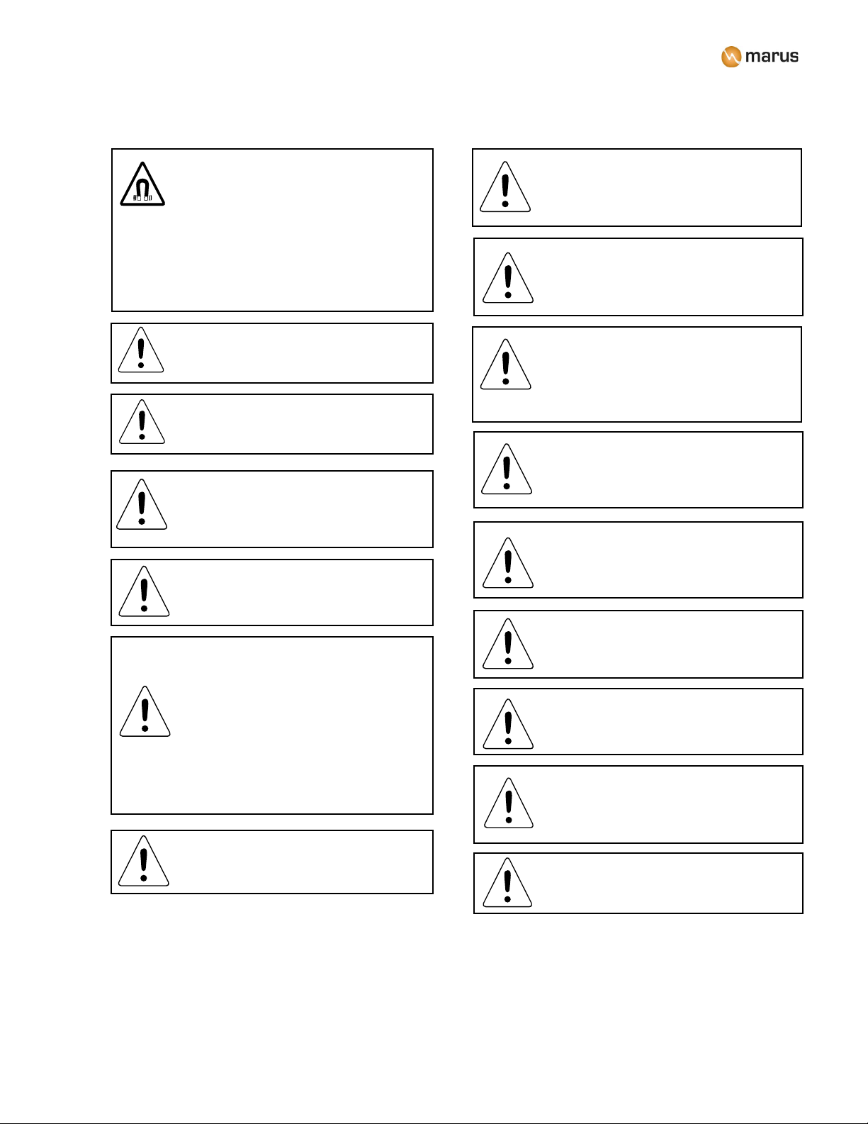
WARNING: Disinfect only by wiping,
no spray disinfection. Please be
aware that the manufacturer expressly
rejects any claims for warranty or
damages when using other cleaning
and disinfection solutions.
**Iodophor-based disinfectants will cause yellow staining on many surfaces.
Quaternary Ammonium
Chemical Composition

631064 R00
CLEANING UPHOLSTERY*
While staining and soiling exposures are common to upholstery fabrics, most may be removed by using
the following cleaning methods.
Light Soiling
• Use a solution of 10% household liquid dish soap with warm water and apply with a soft, damp
cloth. Be sure to rinse away any remaining solution from the chair’s surface.
• If stubborn dirt remains as a stain embedded in the grain of the vinyl use a soft brush, and if
necessary, a touch of cleaning powder or other household cleanser. In both situations, rinse and
dry with a soft cloth.
Heavy Soiling
• Dampen a soft, white cloth with naphtha (lighter uid) or rubbing alcohol and rub gently. Rinse
with a water dampened cloth to remove any remaining concentration.
Other Tips
• To clean stained or soiled areas, a soft white cloth is recommended. Avoid use of paper towels.
• To restore luster, a light coat of spray furniture wax may be used. Apply for 30 seconds and follow
with a light bufng using a clean, white cloth.
• When using strong cleaning agents such as rubbing alcohol or bleach, it is advisable to rst test in
an inconspicuous area to determine potential damage to the material.
• Never use harsh solvents or cleaners which are intended for industrial application.

7
31064 R00
CHAIR SETUP AND INSTALLATION
Before You Begin
Recommended Tools:
• 9/16” wrench
• Scissors
• 1/8” hex wrench
• 1/4” hex wrench
• Depending on the application, the chair’s
upholstery may or may not be installed at the
factory. If the upholstery is not installed, refer to
the specic Upholstery Installation Instructions
shipped with the chair. (It is recommended that
the upholstery not be installed until the entire
unit is set up.)
• Study the overall dimensions of the chair shown
below. Make sure the chair will have sufcient
clearance when in both the upper and lower
extremes of travel, including travel of the chair’s
backrest.
• Gather all necessary tools listed at right.
• Locate the chair hardware kit. During the
installation process several parts in this kit will
be referred to.
Chair Dimensions
57” (147 cm)
50” (127 cm)
29” (74 cm)
33” (84 cm)
8.5” (22 cm)
27” (69 cm)
25” (63.5 cm)
28” (71 cm)
60°
18” (46 cm)
76” to 82” (193 to 208 cm)
12”
(31 cm)
20”
(51 cm)

831064 R00
CHAIR INSTALLATION
1. Remove the carton lid and sides from the
pallet as well as the packing material. Using
a 9/16” wrench, remove the bolts holding the
base plate to the pallet and cut the retaining
straps.
2. Carefully slide the chair from the pallet to the
location to be installed.
WARNING: Chair weight is in excess of 300
pounds. Use an assistant to safely position
the chair.
Figure 1
Figure 2
4. Raise the chair back from its shipping
position and attach back link onto link
pin (gure 1). Using a 3/32” hex wrench,
tighten set screw on back link so that chair
back is rmly retained.
3. Verify that the chair base is on a level surface
and does not rock due to high or low spots
on the oor. If the surface is uneven, use
the supplied leveling pads found in the chair
hardware kit to eliminate gaps between the
oor and the chair base.
5. Locate and unpack the
chair’s seat cushion and
remove the cushion from
the rail. Do not use a knife
to remove the plastic cover.
Tear at perforated line and
pull the cover off.
6. Using the supplied
hardware, attach the
upholstery toe rail to the
chair’s upper structure as
indicated (gure 2) using a
9/16 wrench or socket.
Note: If the chair is NOT to be used as
a stand alone unit, refer to the delivery
unit installation instructions and install the
delivery unit onto the chair prior to continuing
this procedure.
Back Link
Dowel Pin
Set Screw
Seat Cushion
Guide Rails
Chair Upper Structure

9
31064 R00
Chair Control Functions
Swivel Brake Handle
Locate brake handle below the chair
back. Moving the handle to the right
will unlock the chair’s upper chassis
and allow it to swivel 30° left or right.
Moving the handle back to the left
will re-engage the brake and lock the
chair into position.
Swivel Brake Handle
Figure 3
CHAIR INSTALLATION (Cont’d)
7. Hook two (2) places onto the
seat rail as shown in gure 3.
8. Turn the handle to attach the
front of the cushion to the seat
rail.
9. This completes the installation
procedure for the chair’s
upholstery.
Hooks
Handle
7
8
Swivel
Brake
Lock Swivel
Unlock Swivel

10 31064 R00
Quick Release Double-Articulating Headrest
The headrest is adjusted by pressing the large
release button. This unlocks both articulating
joints allowing the desired position to be set
quickly and accurately. To set the height, simply
pull the headrest upward, away from the chair
back until the correct position is found. To
lower the headrest, push it downward into the
chairback.
Glide Bar Tension Adjustment
1. From the rear of the chair, remove the right
side mounting screw of the chair’s back
cover (see gure at right).
2. Insert a 3/32 hex wrench into the hole down
to the tensioning set screw. Turning the
set screw clockwise increases glide bar
tension, counter-clockwise will decrease
tension. Once the desired tension is set,
reinstall the 1/4-20 button head cap screw.
Note the location of the warning label on
the opposite side of the glide bar. Do not
use the head rest when the red line on the
warning label is visible; it is extended too far
out at this point and damage or injury may
result.
Double Articulating Headrest
CHAIR FUNCTIONS (Cont’d)
Safety Stop Cover
Located on lower back cover. This moving
cover has an electric switch that will stop
downward movement of the chair base if
triggered.
WARNING: Do not place anything
under the chair base cover while the
chair is operating, as injury could
result if the safety circuit fails.
Safety Cover
Headrest
Rotation
1/4-20 Button
Head Cap Screw
Release
Button
Warning
Label
WARNING: Support the patient’s
head when adjusting the headrest.

11
31064 R00
Swing-Out Arm Rests
The arm rests can rotate outward and will set in either
of two positions (out at 63.5 degrees or back at 127
degrees). Simply push the toe end of the arm rest
outwards until it rotates to one the desired positions.
Pushing back towards the center of the chair will return
the arm rest to its original position. There is a rotation
stop in the arm to prevent the arm rest from rotating
inwards toward the patient.
Positioning for Wheelchair Patients
Your chair can easily be converted to accommodate
wheelchair patients. Remove the headrest by pulling upward
out of the chair back; reinstall the headrest in a reversed
position as shown. Loosen the adjustment knob and adjust
headrest into desired position.
CHAIR CONTROL FUNCTIONS (Cont’d)
63.5°
63.5°
WARNING: Use caution when using arm
rests as leverage when exiting the chair as
arms may rotate.

12 31064 R00
CHAIR CONTROL FUNCTIONS (Cont’d)
Touchpad Back Control
0
1
Learn Button
Position #1
Position #2
Chair Base Height
Adjustment Buttons
Backrest Incline
Adjustment Buttons
(Press once to activate)
(under Marus logo)
(Press once to activate)
Touchpad Location
Both Sides
Operating the Automatic Positions
The “0” and “1” buttons access programmable operating
positions, also shown below. The exit “0” position is pre-
programmed at the factory.
Programming the “1” Position
Adjust the chair to the desired position.
Press and hold the “Learn” button. The chair will
beep once to conrm. Continue holding the “Learn” button
while pressing the desired auto button “1” two times, then
listen for one quick beep to conrm the position has been
stored.
Return the chair to the “0” or exit position. Press the
“1” button and conrm the position has been correctly
programmed.
Programming the “0” Position
The exit or “0” position can be reprogrammed to the
desired position in the same manner as above.

13
31064 R00
CHAIR CONTROL FUNCTIONS (Cont’d)
Electronic Foot Control
The electronic foot control allows the user to control the
chair’s manual base and back movement and access
the automatic positions.
Foot Control Operation and Programming
Programmable
Operating Position
Learn
Button
Fixed Exit
Position
Operating the Automatic Positions
The “0” and “1” buttons access programmable
operating positions, also shown below. The exit “0”
position is pre-programmed at the factory.
Programming the “1” Position
Press the “0” button on foot switch or touchpad.
Chair will cycle to the exit or “0” position.
Manually position the chair to the desired working
position.
Press and hold the “Learn” button and Double-tap the
“1” button, then listen for one quick beep to conrm
the position has been stored.
Return the chair to the “0” or exit position. Press the
“1” button and conrm the position has been correctly
programmed.
Programming the “0” Position
The exit or “0” position can be reprogrammed to the
desired position in the same manner as above.
NOTE: At start up or after a power interruption,
the chair will need to be reset to access the
programmable positions. This is done by returning
the chair to the exit position (“0”) and then waiting
at least 30 seconds prior to operation.

14 31064 R00
ELECTROMAGNETIC COMPATIBILITY
Electrical medical devices are subject to special EMC safety measurements and as a result
the equipment must be installed according to the installation instruction manual.
PORTABLE ELECTRONIC DEVICES
Portable and mobile high frequency electronic communications equipment may interfere with
electronic medical devices.
STATIC SENSITIVE DEVICES
Where labeled this equipment contains static sensitive devices that require special
precautions when handling. At a minimum, a grounded wrist strap that is connected to ground
stud should be worn to reduce the possibility of damage to the equipment.
MEDICAL ELECTRICAL EQUIPMENT
ELECTROMAGNETIC COMPATIBILITY
(TECHNICAL DESCRIPTION)
ELECTROMAGNETIC COMPATIBILITY testing has been done for this product.
ACCESSORY USE
Using accessory devices not specied by the manufacturer for use with their equipment may
result in an increase of electromagnetic emissions and/or a decrease in electromagnetic
immunity of the system. Do not use any accessories not authorized or approved by the
manufacturer.
INTERFERENCE FROM OTHER EQUIPMENT
If other equipment is used adjacent to or stacked with this equipment the system must be
observed to verify normal operation.
MEDICAL ELECTRICAL EQUIPMENT ELECTROMAGNETIC COMPATIBILITY
(Instructions for use)
ATTENTION
OBSERVE PRECAUTIONS
FOR HANDLING
ELECTROSTAT IC
SENSITIVE DEVICES
ELECTROMAGNETIC COMPATIBILITY

15
31064 R00
This product is intended for use in the electromagnetic environment specied below. The customer or
the user of this product should ensure that it is used in such an environment.
UTis the AC. mains voltage prior to application of the test level.
Guidance and manufacturer‘s declaration-electromagnetic immunity
IMMUNITY TEST IEC60601 TEST LEVEL COMPLIANCE LEVEL ELECTROMAGNETIC
ENVIRONMENT GUIDANCE
ELECTROSTATIC DISCHARGE
(ESD) IEC 61000-4-2
61000-4-2
+/-6 kV contact
+/-8 kV air
+/-6 kV contact
+/-8 kV air
Floors should be wood, concrete
or ceramic tile. If oors are
covered with synthetic material
the relative humidity should be
at least 30%. Where labeled,
a ground strap (connected to
ground lug) should be worn
to reduce the possibility of
damaged to the unit when
servicing.
ELECTRICAL FAST
TRANSIENT/BURST
IEC 61000-4-4
Capacitive Clamp
+/-1 kV, 5/50 nsec pulse
+/-5 kHz repetition frequency
Direct Injection
+/-2 kV, 5/50 nsec pulse
+/-5kHz repetition frequency
Capacitive Clamp
+/-1 kV, 5/50 nsec pulse
+/-5 kHz repetition frequency
Direct Injection
+/-2 kV, 5/50 nsec pulse
+/-5kHz repetition frequency
Mains power quality should be
that of typical commercial or
hospital environment.
SURGE IEC 61000-4-5 +/-1 kV differential mode
+/-2 kV common mode
+/-1 kV differential mode
+/-2 kV common mode
Mains power quality should be
that of typical commercial or
hospital environment.
VOLTAGE DIPS, SHORT
INTERRUPTIONS AND VOLT-
AGE VARIATIONS ON POWER
SUPPLY INPUT LINES
IEC 61000-4-11
30% reduction, 500 ms
60% reduction, 100 ms
>95% reduction, 10 ms
>95% reduction, 5000 ms
30% reduction, 500 ms
60% reduction, 100 ms
>95% reduction, 10 ms
>95% reduction, 5000 ms
Mains power quality should
be that of typical commercial
or hospital environment. If
the user requires continued
operation during power mains
interruptions, it is recommended
that the product be powered by
an uninterrupted power supply or
battery.
POWER FREQUENCY (50/60
HZ) MAGNETIC FIELD IEC
61000-4-8
3 A/m 3 A/m Power frequency magnetic elds
should be at levels characteristic
of a typical location in a
typical commercial or hospital
environment.
ELECTROMAGNETIC COMPATIBILITY

16 31064 R00
NOTE 1: At 80 MHz to 800 MHz, the higher frequency range applies.
NOTE 2: These guidelines may not apply in all situations. Electromagnetic propagation is affected by absorption and
reection from structures objects and people.
a) Field strengths from xed transmitters, such as base stations for radio (cellular/cordless) telephones and land mobile
radios, amateur radio, AM and FM radio broadcast and TV broadcast cannot be predicted theoretically with accuracy.
To assess the electromagnetic environment due to xed RF transmitters, an electromagnetic site survey should be
considered. If the measured eld strength in the location in which the product is used exceeds the applicable RF
compliance level above, the product should be observed to verify normal operation. If abnormal performance is
observed, additional measures may be necessary, such as re-orienting or relocating the product.
b) Over the frequency range 150 kHz to 80 MHz, eld strengths should be less than 3/Vm.
This product is intended for use in the electromagnetic environment specied below. The customer or the
user of this product should assure that it is used in such an environment.
Guidance and manufacturer's declaration-electromagnetic immunity
Portable and mobile RF communications
equipment should be used no closer to
any part of the product, including cables,
than the recommended separation
distance calculated from the equation
applicable to the frequency of the
transmitter.
Immunity Test IEC60601 Test Level Compliance Level
Conducted RF
IEC 61000-4-6
3 Vrms
150 kHz to 80 MHz
Where P is the maximum output
power rating of the transmitter in
watts (W) according to the transmitter
manufacturer and d is the recommended
separation distance in meters (m).
-
Field strengths from xed RF
transmitters, as determined by an
electromagnetic site survey, (a) should
be less than the compliance level in
each frequency range. (b)
-
Interference may occur in the vicinity
of equipment marked with the following
symbol:
ELECTROMAGNETIC ENVIRONMENT
GUIDANCE
d= 1.2 √¯ P 80 MHz 800 MHz
d= 2.3 √¯ P 800 MHz 2.5 GHz
Radiated RF
IEC 61000-4-3
3 V/m
80 kHz to 2.5 MHz
3 Vrms
3 V/m
ELECTROMAGNETIC COMPATIBILITY
d= 1.2 √¯ P

17
31064 R00
ELECTROMAGNETIC COMPATIBILITY
Guidance and manufacturer‘s declaration-electromagnetic emissions
This product is suitable for use in all establishments,
other than domestic establishments and those directly
connected to the public low voltage power supply
network that supplies buildings used for domestic
purposes.
This product uses RF energy only for its internal
function. Therefore, the emissions are very low
and are not likely to cause any interference in
nearby electronic equipment.
RF emissions
CISPR-11
RF emissions
CISPR-11
This product is intended for use in the electromagnetic environment specied
below. The customer or the user should
assure that it is used in such an
environment.
Voltage Fluctuations / icker
Emissions
IEC 61000-3-3
Emissions Test Electromagnetic Environment guidance
Compliance
Harmonic Emissions
IEC 61000-3-2
Group 1
Class B
Class B
Complies
Guidance and manufacturer‘s declaration-electromagnetic emissions
This product uses RF energy only for its internal
function. Therefore, the emissions are very low
and are not likely to cause any interference in
nearby electronic equipment.
RF emissions
CISPR-11
RF emissions
CISPR-11
This product is intended for use in the electromagnetic environment specied
below. The customer or the user should
assure that it is used in such an
environment.
Voltage Fluctuations / icker
Emissions
IEC 61000-3-3
Emissions Test Electromagnetic Environment guidance
Compliance
Group 1
Class B
Class B
Complies

18 31064 R00
CHECKLIST
Verify the following after installation or servicing of the chair:
All manuals are present.
All labels are present and legible.
The chair is installed/assembled correctly and there is no mechanical damage on
new installations.
The chair can be moved and positioned freely without any drifting.
The chair is connected to the appropriate power source.
Dispose of all product parts and internal components per applicable codes, regulations
and directives.
The chair is setting on a level surface and has been properly leveled. Refer to installation
instructions for information on how to properly level the unit.
All hardware is installed correctly and all connections are properly attached.
If applicable, the cover is closed and fasteners tightened (take care not to
pinch tubing on wires).
When depressing the touchpad (if applicable), the chair functions properly.
While running the chair ensure there is nothing leaking from the tubing.
The chair passes a high pot test.
All terminals are connected securely.
The chair passes a ground continuity test.
The internal wiring is in good shape and not frayed.
Table of contents
Popular Indoor Furnishing manuals by other brands

DH Casual
DH Casual DAYTONA quick guide

Pyramat
Pyramat Sound Rocker S 2000 owner's manual

Mocka
Mocka Kirra Bedside Table Assembly instructions

modway
modway EEI-5471 Assembly instructions

Argos
Argos Under Basin Unit 833/2763 Assembly instructions

Phoenix
Phoenix FS2410K Instructions & Guarantee Registration

Next
Next AMELIA 145641 Assembly instructions

COLLECTION AB
COLLECTION AB KRETA BK 180 Assembly instructions

GoodHome
GoodHome imandra 3663602933434 manual

Riverside Furniture
Riverside Furniture 46680 Assembly instructions

FMD Furniture
FMD Furniture FRAME 10 Assembly instructions

Emmezeta
Emmezeta ALICANTE ATCK03 Assembling instructions