Marvair AVPA 12 series User manual

MODELS:
AVPA 12-20-24-30-36-42-48-60-72
HVESA 36-42-49-60
HVEA 24-30-36-42-49-60
AVHA 12-20-24-30-36-42-48-60
Installation & Operation Manual
9-11 EER Vertical Wall-Mount Air Conditioners
Manufactured By:
A Division of the AIRXCEL®Commercial Group
P.O. Box 400 • Cordele, Georgia 31010 • 156 Seedling Drive • Cordele, Georgia 31015
(229) 273-3636 • Fax (229) 273-5154
E-mail: marvairsales@airxcel.com • Internet: www.Marvair.com
The most current version of this manual can be found at www.Marvair.com.
IMPORTANT
This manual may include information for options and features which may not be
included on the unit being installed. Refer to the unit data label or Model Identication
to determine which features and options this unit is equipped with.
INSTALLER: Afx the instructions on the inside of the building adjacent to the thermostat.
END USER: Retain this manual for future reference.
Marvair ComPac Installation & Operation Manual 12/2017 Rev.16
Part #01655
Air Conditioner Product Manual
Vertical Wall-Mount Air Conditioners
with Front Control Box Panel

2
Marvair ComPac Installation & Operation Manual
12/2017 Rev.16
How To Use This Manual
This manual is intended to be a guide to Marvair ComPac family of vertical air conditioners. It contains installation,
troubleshooting, maintenance, warranty, and application information. The information contained in this manual is to be
used by the installer as a guide only. This manual does not supersede or circumvent any applicable national or local codes.
If you are installing the ComPac unit, rst read Chapter 1 and scan the entire manual before beginning the installation as
described in Chapter 2. Chapter 1 contains general, descriptive information and provides an overview which can speed
up the installation process and simplify troubleshooting.
If a malfunction occurs, follow this troubleshooting sequence:
1. Make sure you understand how the ComPac unit works (Chapters 1 & 3).
2. Identify and correct installation errors (Chapter 2).
3. Refer to the troubleshooting information in Chapter 4.
If you are still unable to correct the problem, contact the Factory at 1-800-841-7854 for additional assistance.
Please read the following “Important Safety Precautions” before beginning any work.
Important Safety Precautions
1. USE CARE when LIFTING or TRANSPORTING equipment.
2. TRANSPORT the UNIT UPRIGHT. Laying it down on its side may cause oil to leave the compressor and breakage
or damage to other components.
3. TURN ELECTRICAL POWER OFF AT THE breaker or fuse box BEFORE installing or working on the equipment.
LINE VOLTAGES ARE HAZARDOUS or LETHAL.
4. OBSERVE and COMPLY with ALL applicable PLUMBING, ELECTRICAL, and BUILDING CODES and ordinances.
5. SERVICE may be performed ONLY by QUALIFIED and EXPERIENCED PERSONS.
* Wear safety goggles when servicing the refrigeration circuit
* Beware of hot surfaces on refrigerant circuit components
* Beware of sharp edges on sheet metal components
* Use care when recovering or adding refrigerant
6. Use COMMON SENSE - BE SAFETY-CONSCIOUS
This is the safety alert symbol . When you see this symbol on the ComPac unit and in the instruction manuals
be alert to the potential for personal injury. Understand the signal word DANGER, WARNING, CAUTION and
IMPORTANT. These words are used to identify levels of the seriousness of the hazard.
DANGER Failure to comply will result in death or severe personal injury and/or property damage.
WARNING Failure to comply could result in death or severe personal injury and/or property damage.
CAUTION Failure to comply could result in minor personal injury and/or property damage.
IMPORTANT Used to point out helpful suggestions that will result in improved installation, reliability or
operation.
© 12/2017 Airxcel Commercial Group
SPECIFICATIONS SUBJECT TO CHANGE WITHOUT NOTICE.

Marvair ComPac Installation & Operation Manual
12/2017 Rev.16
3
WARNING
• If the information in these instructions are not followed exactly, a re may result causing
property damage, personal injury or loss of life.
• Read all instructions carefully prior to beginning the installation. Do not begin
installation if you do not understand any of the instructions.
• Improper installation, adjustment, alteration, service or maintenance can cause property
damage, personal injury or loss of life.
• Installation and service must be performed by a qualied installer or service agency in
accordance with these instructions and in compliance with all codes and requirements
of authorities having jurisdiction.
INSTALLER: Afx the instructions on the inside of the building adjacent to the
thermostat.
END USER: Retain these instructions for future reference.
Table of Contents
Chapter 1 ComPac Description & Specications
1.1 General Description .................................................................................................................................5
1.2 Model Identication .................................................................................................................................5
1.3 Serial Number Date Code ........................................................................................................................5
1.4 Air Flow, Weights and Filter Sizes...........................................................................................................6
1.5 General Operation ....................................................................................................................................6
1.6 Electronic Control Board Mode of Operation..........................................................................................7
1.7 Optional Controls and Packages ..............................................................................................................9
1.8 Electrical Operation ...............................................................................................................................11
1.9 Economizer Components .......................................................................................................................18
Chapter 2 Installation
2.1 Equipment Inspection.............................................................................................................................22
2.2 Installation Requirements.......................................................................................................................22
2.3 Installation Materials .............................................................................................................................24
2.4 Porting and Duct Work ..........................................................................................................................25
2.5 Fresh Air Hood Installation ...................................................................................................................28
2.6 Bracket Installation ...............................................................................................................................28
2.7 Mounting the Unit .................................................................................................................................28
2.8 Vertical Economizer and Gravity Dampers (HVESA 36 & 60 Models Only).......................................30
2.9 Electrical Connections ...........................................................................................................................31
Chapter 3 Start-Up
3.1 Check-Out of Cooling Cycle .................................................................................................................35
3.2 Check-Out of Heating Cycle..................................................................................................................35
Chapter 4 Troubleshooting
4.1 Overview ................................................................................................................................................36
4.2 Failure Symptoms Guide........................................................................................................................36
4.3 Compressor Troubleshooting .................................................................................................................37
4.4 Control Board Diagnosis........................................................................................................................38

4
Marvair ComPac Installation & Operation Manual
12/2017 Rev.16
Table of Contents
Chapter 5 Maintenance
5.1 Scheduled Maintenance .........................................................................................................................39
Chapter 6 Warranty
6.1 Airxcel Commercial Group Limited Product Warranty.........................................................................40
Parts List and Exploded Views .....................................................................................................................41
Appendix A
Installation Instructions for Field Installed Electric Heaters ...........................................................................42
Illustrations
Figure 1a. Typical Electrical Schematic - Model AVPA & AVHA..............................................................12
Figure 1b. Typical Electrical Schematic - Model AVPA & AVHA..............................................................13
Figure 1c. Typical Electrical Schematic - Model HVEA............................................................................14
Figure 1d. Typical Electrical Schematic - Model HVEA ............................................................................15
Figure 1e. Typical Electrical Schematic - Model HVESA (Alternate Construction).................................16
Figure 1f. Typical Electrical Schematic - Model HVESA (Alternate Construction)..................................17
Figure 2. Dry Bulb sensor..........................................................................................................................19
Figure 3. Enthalpy Sensor Temperature Control Points ............................................................................20
Figure 4. Electrical Controls, HVESA Alternate Construction .................................................................20
Figure 5. Economizer Control Board ........................................................................................................21
Figure 6. Back Panel Conguration for AVPA/AVHA12 Air Conditioners ..............................................26
Figure 7a. Fresh Air Hood Damper, Models 24-72.....................................................................................28
Figure 7b. Fresh Air Hood Damper, Models AVPA/AVHA12 ....................................................................28
Figure 8a. Wall Mounting Detail.................................................................................................................29
Figure 8b. Wall Mounting Detail.................................................................................................................29
Figure 9a. Humidistat Wiring Details..........................................................................................................33
Figure 9b. Thermostat Connection Diagram ...............................................................................................33
Figure 9c. CommStat™ Touch HVAC Controller Wiring Detail................................................................34
Figure 9d. CommStat™ 3 HVAC Controller Wiring Detail........................................................................34
Tables
Table 1 CFM @ External Static Pressure .................................................................................................6
Table 2 Return Air Filter Sizes .................................................................................................................6
Table 3 Shipping Weights .........................................................................................................................6
Table 4 Minimum Clearances.................................................................................................................23
Table 5 Voltage Limitations....................................................................................................................24
Table 6 Maximum Static Pressure ..........................................................................................................27

Marvair ComPac Installation & Operation Manual
12/2017 Rev.16
5
Chapter 1 Description & Specications
1.1 General Description
The Marvair ComPac® is a series of vertical wall-mounted air conditioning systems that provide heating,
cooling, and ventilation for electronic equipment shelters, process control centers, and other applications
with high internal heat gains. The series includes multiple sizes and nominal cooling capacities from
11,000 to 72,000 BTUH. Resistance heating elements are available in various wattages.
The AVPA models are available with nominal cooling capacities of 12,000 to 72,000 BTUH’s and
Energy Efciency Ratios (EER’s) of 9.0 to 10.0. The AVHA models are available with nominal cooling
capacities of 12,000 to 60,000 BTUH’s and EER’s of 10.0. HVEA modes are available with cooling
capacities of 24,000 to 60,000 BTUH and EER’s of 10.50 to 11.75. HVESA models are identical to
the HVEA models, but have a 2-stage compressor. The ComPac Product Data Sheets have detailed
information on the capacities and efciencies for each model.
See Appendix A for instructions on eld installation of electric heat.
ComPac air conditioners feature an exclusive electronic control board. The control board consolidates
several of the electrical components and improves the air conditioner’s reliability. The control board
replaces the blower relay, the lockout relay, the compressor time delay and the timed low pressure
bypass. In addition, the control board has LED’s to indicate operating status and fault conditions to
assist the service technician. A complete description of functions of the control board is in Section 1.6.
ComPac and models are designed for easy installation and service. Major components are accessible
for service beneath external panels.
All units have internal disconnects (optional on 380V and 575V). Depending upon state and local code
requirements, this feature may eliminate the need for an external breaker or disconnect.
ComPac units have a 0-15% manual outside air damper as standard equipment. Marvair ComPac models
are available with an optional factory installed economizer for 100% free cooling with outside air.
1.2 Model Identication
The model identication number is found on the data sticker. Rating plate located on side panel.
Unused = Marvair
ComPac
EUB = Eubank
WalPac
Cabinet Color
100 = Marvair Beige
200 = Gray
400 = White
800 = Eubank Mesa Tan
A5 = Built in
compliance with
UL 1995, 4th edition
AVP
AVH
HVE
Nominal Cooling
12 = 11,000 BTUH
20 = 20,000 BTUH
24 = 24,000 BTUH
30 = 30,000 BTUH
36 = 36,000 BTUH
42 = 42,000 BTUH
48/49 = 48,000 BTUH
60 = 60,000 BTUH
72 = 72,000 BTUH
System Type
Air Conditioner
Power Supply
A = 208/230V,1ø,60Hz
C = 208/230V,3ø,60Hz
D = 460V,3ø,60Hz (3 wire)
Z = 575V,3ø,60Hz
Configuration
N = Non-Economizer
C = Economizer
Electric Heat – kW
000 = No Heat
022 = 2.2 kW
036 = 3.6 kW
040 = 4 kW
050 = 5 kW
060 = 6 kW
Special Option Code
R = Electric Reheat
U = Scroll Compressor
X = Hot Gas Bypass
O = Opposite side
compressor
E = Extreme Duty
D = Desert Duty
G = Hot Gas Reheat
2-Stage
Compressor
••• S A •• AC • ••• • • A5 ••• •••
Refrigerant
A = R410A 080 = 8 kW
090 = 9 kW
100 = 10 kW
120 = 12 kW
150 = 15 kW
1.3 Serial Number Date Code
A = January E = May J = September D = 2014 H = 2018
B = February F = June K = October E = 2015 I = 2019
C = March G = July L = November F = 2016 J = 2020
D = April H = August M = December G = 2017 K = 2021

6
Marvair ComPac Installation & Operation Manual
12/2017 Rev.16
1.4 Air Flow, Weights and Filter Sizes
Complete electrical and performance specications and dimensional drawings are in the Marvair
ComPac Product Data Sheets.
MODEL 0.10 0.15 0.20 0.25 0.30 0.40 0.50
AVPA/AVHA12 450 420 390 360
AVPA24/AVHA20/24 860 825 810 740 670
AVPA/AVHA30 1100 1050 1000 960 920 810
AVPA/AVHA36 1310 1265 1220 1185 1150 1060
AVPA/AVHA42 1650 1585 1520 1450 1360
AVPA/AVHA48 1900 1830 1760 1700 1620
AVPA/AVHA60 1900 1830 1760 1700 1620
AVPA72 2100 1950 1800 1730 1660
HVEA24 800 785 770 725 680 600 500
HVEA30 1200 1150 1100 1050 1000 900 800
HVEA36 1290 1230 1170 1115 1060 1000 920
HVEA42 1500 1430 1360 1295 1230 1160 1070
HVEA49 1900 1850 1800 1700 1600 1500 1350
HVEA60 1900 1850 1800 1700 1600 1500 1350
HVESA36 1290 1230 1170 1115 1060 1000 920
HVESA42 1500 1430 1360 1295 1230 1160 1070
HVESA49 1900 1850 1800 1700 1600 1500 1350
HVESA60 1900 1850 1800 1700 1600 1500 1350
Values in bold are the minimum air flow.
Air flow ratings of 208-230 volt units are at 230v. Air flow ratings of 460 volt units are at 460 volts. Operation
of units at a voltage different from the rating point will affect air flow.
Table 1. CFM @ External Static Pressure (Wet Coil) (IWG)
MODEL INCHES MILLIMETERS PART NUMBER FILTERS PER UNIT MERV RATING
AVPA/AVHA12 (Non-Economizer) 20 x 10 x 2 508 x 254 x 52 91974 1 7
AVPA/AVHA12 (With Economizer) 22¼ x 6¼ x 2 565 x 159 x 51 80172 1 7
AVPA24/AVHA20/24 25 x 16 x 2 635 x 406 x 52 80137 1 7
AVPA/AVHA30/36 & HVEA24 30 x 16 x 2 762 x 406 x 52 80138 1 7
AVPA/AVHA42/48/60 &
HVEA30/36/42 & HVESA36/42 36½ x 22 x 2 927 x 559 x 52 80162 1 7
AVPA72 & HVEA49/60 & HVESA49/60 18 x 24 x 2 457 x 610 x 52 81257 2 7
Table 2. Return Air Filter Sizes
MODEL LBS KG
ComPac Non-Economizer
AVPA/AVHA12 175 79.5
AVPA24/AVHA20/24 275 125
AVPA/AVHA30/36 & HVEA24 355 160
AVPA/AVHA42/48/60 & HVEA30/36 & HVESA36/42 535 245
HVEA49/60 & HVESA49/60 625 284
ComPac With Economizer
AVPA/AVHA12 185 84.1
AVPA24/AVHA20/24 286 130
AVPA/AVHA30/36 & HVEA24 375 170
AVPA/AVHA42/48/60 & HVEA30/36 & HVESA36/42 590 268
HVEA49/60 & HVESA49/60 640 291
Table 3. Shipping Weights for ComPac
1.5 General Operation
Refrigerant Cycle (Cooling Mode)
Marvair ComPac air conditioners use R-410A refrigerant in a conventional vapor-compression refrig-
eration cycle to transfer heat from air in an enclosed space to the outside. A double blower assembly
blows indoor air across the evaporator. Cold liquid refrigerant passing through the evaporator is boiled
into gas by heat removed from the air. The warmed refrigerant gas enters the compressor where its

Marvair ComPac Installation & Operation Manual
12/2017 Rev.16
7
temperature and pressure are increased. The hot refrigerant gas condenses to liquid as heat is transferred
to outdoor air drawn across the condenser by the condenser fan. Liquid refrigerant is metered into the
evaporator to repeat the cycle.
Heating Mode
A wall-mounted thermostat controls the heating cycle of models which incorporate resistance heating
elements. On a call for heat, the thermostat closes the heat relay to energize the indoor fan and the
resistance elements. Except on units with the optional dehumidication kit, the compressor is locked
out during the heating cycle. Please see Appendix A for instructions on eld installing electric heaters.
Economizer Operation
The economizer is a regulated damper system with controls. The damper regulates the circulation of
outside air into the enclosure (when the outdoor air conditions are suitable) to reduce the need for
mechanical cooling, save energy, and extend compressor life.
Depending upon the options selected, the damper responds to the enthalpy of the outdoor air. On a call
for cooling from a space thermostat, it operates as follows:
When the enthalpy of the outdoor air is below the set point, the outdoor air damper is proportionally
open (and return air damper is proportionally closed) to maintain between 50°F and 56°F (10°C to
13°C) at the mixed/discharge air sensor. Integral pressure relief allows the indoor air to exit the shelter
through the air conditioner.
When the enthalpy of the outdoor air is above the set point, the outdoor air damper closes to its minimum
position. A call for cooling from the space thermostat brings on mechanical cooling.
A built-in adjustable minimum position potentiometer controls the amount of outdoor air admitted to
meet minimum ventilation requirements.
1.6 Electronic Control Board Mode of Operation
Normal
24 VAC power must be continuously applied to “R” and “C”. Upon a call for cooling “Y” and with the
high pressure switch (HPS) closed, the compressor will be energized. (Note: See the delay on make
feature.) The compressor will remain energized during the 3 minute timed low pressure by-pass cycle. If
the low pressure switch (LPS) is open after the 3 minute by-pass cycle, the compressor will de-energize.
Lock-out
If either of the fault conditions (LPS or HPS) occurs twice during the same call for cooling, the control
board will enter into and indicate the lockout mode. In the lockout mode, the compressor is turned off.
If there is a call for indoor air ow “G”, the blower remains energized, the alarm output is energized and
the status LED will blink to indicate which fault has occurred. When the lockout condition is cleared,
the unit will reset if the demand for the thermostat is removed or when the power is reset. With the
control board, the user can now have either normally closed or normally open remote alarm dry contacts.
ComPac®air conditioners are factory wired to be normally open.
Delay on Break
If the compressor is de-energized due to a loss of a cooling “Y” call or the rst fault, the unit re-start
will be delayed 3 minutes from the time the contactor is de-energized. (Note: There is no delay on break
if the lockout condition is reset.)
Delay on Make
On initial power up only, the unit will wait 0.03 to 10 minutes from the cooling “Y” call before

8
Marvair ComPac Installation & Operation Manual
12/2017 Rev.16
allowing the contactor to energize. The delay can be adjusted by the DOM wheel on the board. Factory
recommended wait is 3 minutes.
Low Pressure By-Pass Time
When starting, the low pressure switch (LPS) fault condition will be by-passed for 3 minutes before the
contactor is de-energized.
Post Purge
Upon a call for indoor airow “G” the blower will energize immediately. When in the cooling mode, the
blower will remain energized for 10 to 90 seconds (adjustable) after the compressor has been de-energized.
The time period can be changed by fan purge wheel on the board. Factory setting is 90 seconds.
LED Indicator Lights
COLOR TYPE STATUS DESCRIPTION
Green Power Constant On 24 VAC power has been applied
Red Status Constant On Normal operation
Red Status 1 Blink High pressure switch has opened twice
Red Status 2 Blinks Low pressure switch has opened twice
Low Ambient Control
The low ambient control permits cooling when outdoor ambient temperatures are low. The control uses
a reverse-acting high pressure switch to cycle the condenser fan motor according to liquid refrigerant
pressure conditions. Switch closure and fan operation occurs when the pressure reaches 400 PSIG. The
switch opens again when the refrigerant pressure falls to 290 PSIG. Therefore, the outdoor fan always starts
after the compressor, and it will cycle frequently during normal operation at low outdoor conditions.
High Pressure Switch
The high pressure switch is mounted on the liquid line. It is electrically connected to a lockout circuit
on the board which shuts down the system if the refrigerant pressure rises to 650 PSIG. This protects the
unit if airow through the condenser is blocked or if the outdoor fan motor fails.
Although the contacts of the high pressure switch close when the refrigerant pressure falls to approximately
450 PSIG, the system must be manually reset once the lockout circuit is activated. A manual reset is
necessary to prevent harmful short-cycling. To reset switch, turn primary power off, then back on or turn
thermostat system switch off, then back on.
Low Pressure Switch
The low pressure switch is mounted on the compressor suction line. It is designed to open if the refrigerant
pressure drops to 40 PSIG; it resets when the pressure rises to 60 PSIG. The switch protects the unit if
airow through the indoor blower is impeded, if the blower motor fails, or if there is a loss of refrigerant.

Marvair ComPac Installation & Operation Manual
12/2017 Rev.16
9
LEDs Post Purge Wheel Delay on Make
(Compressor Time Delay)
Wheel
1.7 Optional Controls & Packages
Hard Start Kit
Used on single phase equipment to give the compressor higher starting torque under low voltage condi-
tions. Generally not recommended on units with scroll compressors.
Extreme Duty Package (not available on AVPA12)
The Extreme Duty Package allows selected Marvair ComPac® air conditioners to operate in extremely
cold and hot ambient conditions. The Extreme Duty Kit is always factory installed. Non-economizer
ComPac air conditioners will operate from 0° F to 131° F (-18° to 55°C). Economizer equipped ComPac
air conditioners will operate from -40° F to 131° F (-40° to 55°C).
The Extreme Duty Package includes a suction line accumulator, thermal expansion valve (TXV),
crankcase heater, hard start kit, an auto reset, high pressure switch and an outdoor thermostat and fan
cycle switch. The fan cycle control is standard on all ComPac air conditioners and operates based upon
the liquid line pressure. The outside thermostat closes whenever the outside temperature is below 50°F
(10°C) and opens when the outside temperature is 50° F (10°C) or higher. Whenever the temperature
is below 50°F (10°C), the fan cycle switch is in the circuit; when temperatures are 50° F (10°C) or
higher, the fan cycle switch is not in the circuit. The fan cycle control is used with a TXV to prevent
excessive cycling or "hunting" of the TXV.
Protective Coating Packages
Typically only the non-economizer ComPac are used in corrosive environments, but the ComPac with
an economizer is also available with corrosion protection. Two corrosion protection packages are of-
fered- one for the condenser section (the Coastal Environmental package) and the other for the entire
unit (the Coat-All Package).
The Coastal Environmental Package includes:
• Corrosion resistant fasteners
• Sealed or partially sealed condenser fan motor
• Protective coating applied to all exposed internal copper and metal in the condenser section
• Protective coating on the condenser coil (Luvata Insitu®) contains ES2 (embedded stainless steel
pigment) technology.
The Coat all Package includes all of the above, plus:
• Protective coating on the evaporator coil (Luvata Insitu®) contains ES2 (embedded stainless steel
pigment) technology
• Protective coating on exterior and interior components and sheet metal. (Note: the internal sheet
metal which is insulated, bottom outside panel, and the internal control box are not coated)
Note: The AVPA12 is available with the protective coatings and corrosion resistant fasteners, but does
not have a sealed condenser fan motor.

10
Marvair ComPac Installation & Operation Manual
12/2017 Rev.16
Hot Gas Bypass (Non-Economizer Models Only) Not available on the AVPA12/24
Used in specialty applications; i.e., Magnetic Resonance Imaging (MRI) buildings, to prevent magnetic
voltage disturbance caused by compressor cycling. Two hot gas bypass option packages are available
to allow operation to 20°F (-7°C) or minus 20°F (-29°C). Please refer to Hot Gas Bypass Application
Bulletin for details.
Electric Reheat Dehumidication Not available on the AVPA12
A humidity controller allows electric heat and cooling to operate simultaneously. Marvair®air conditioners
equipped with the dehumidication option allow the indoor humidity of the controlled environment
to be maintained at or below a certain humidity set point. These units do not have the ability to add
humidity to the building.
IMPORTANT
The electrical wire and breaker or fuses must be sized for simultaneous operation
of the electric heater and the air conditioner. Refer to the data sticker on the unit or
the appropriate Air Conditioner Product Data Sheet for the sizing information.
Dehumidication is achieved by operating mechanical cooling in conjunction with electric reheat. The
strip heat is sized approximately to the sensible capacity of the total tonnage of the machine (i.e., on a
24,000 BTU unit the strip heat is sized at approximately 20,000 BTU). Because the strip heat is sized
to the approximate sensible cooling capacity, only selected models are available.
Operation:
When the humidity rises above the set point on the humidity controller both mechanical cooling and
electric reheat operate to temper the air and lower the humidity. If the temperature in the controlled
environment rises above the set point of the thermostat and the unit is operating in the dehumidication
mode, the call for cooling will override the call for dehumidication and the strip heat is disengaged
until the thermostat is satised. This assures the environment temperature is maintained as rst priority
and humidity control is second.
In applications where a shelter has redundant air conditioning units and is controlled by a lead lag control-
ler (CommStat Touch, CommStat 4, CommStat 3 HVAC Controller), most times the dehumidication
option is only necessary on one of the two units. It is possible for one unit to be operating in the cooling
mode while the unit with dehumidication is operating at the same time. If the cooling unit does not
maintain the shelter temperature set point, the unit with dehumidication will go into the cooling mode.
It does not matter whether the unit with dehumidication is the lead or lag unit.
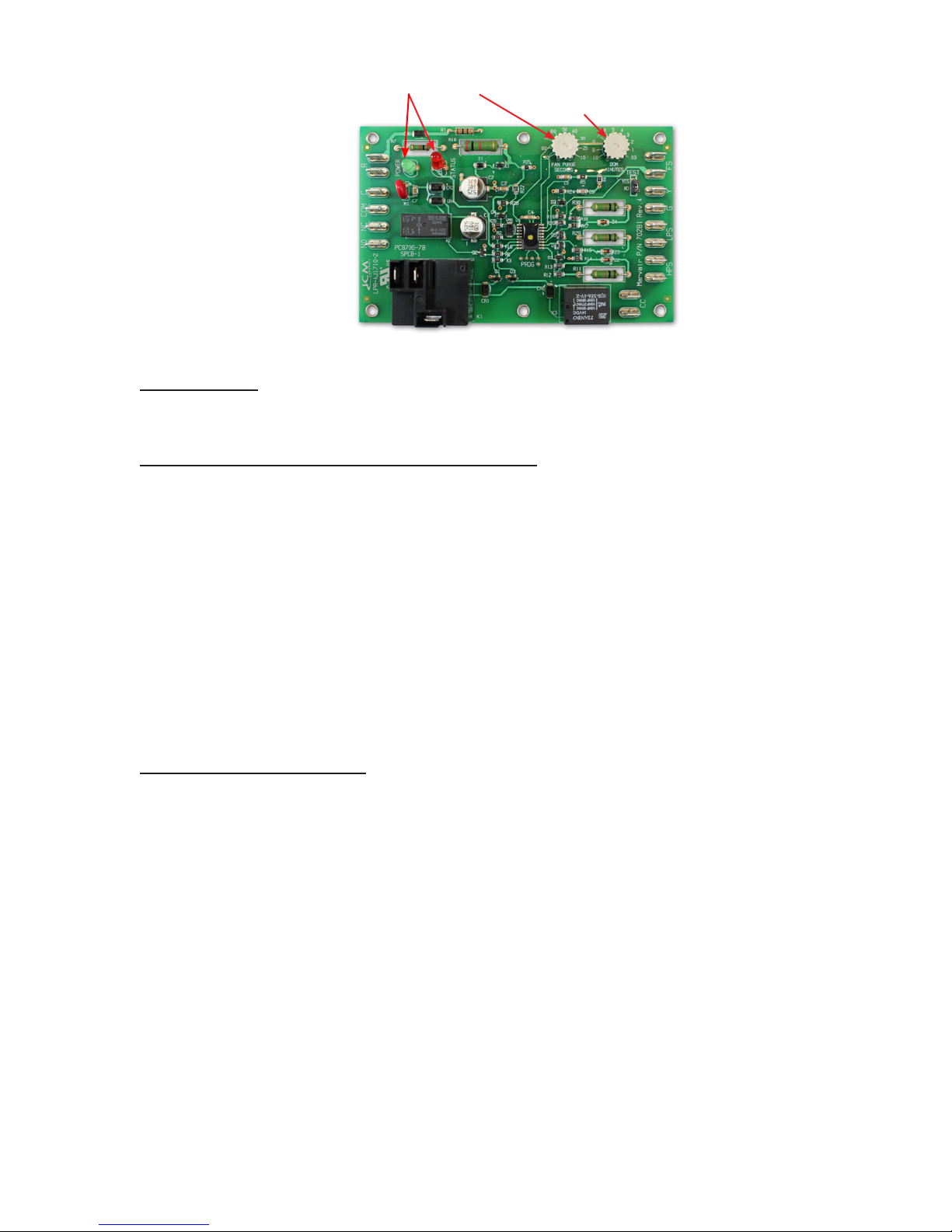
Three Phase Voltage Monitor
Continuously measures the voltage of each of the three phases. The monitor separately senses low
and high voltage, voltage unbalance including phase loss and phase reversal. An LED indicator glows
when all voltages are acceptable. Automatically resets when voltages and phases are within operating
tolerances. Not required on 1ø units.
Dirty Filter Indicator (Not Available on the AVPA12)
A diaphragm type of indicator measures the air pressure on either side of the lter and when the pressure
drops below the set point, a red LED is illuminated. The set point is adjustable.
Protective Coil Coatings
Either the condenser or evaporator coil can be coated, however, coating of the evaporator coil is not
common. For harsh conditions, e.g., power plants, paper mills or sites were the unit will be exposed to
salt water, the condenser coil should be coated. Note: Cooling capacity may be reduced by up to 5%
on units with coated coils.

Marvair ComPac Installation & Operation Manual
12/2017 Rev.16
11
Thermal Expansion Valve
Available on all ComPac®air conditioners. Improves performance in hot ambient temperatures.
High Filtration (Not Available on the AVPA12)
Selected units are built with larger blowers/motors for use with higher efciency lters with MERV
ratings of 11, 13 and 14 when tested to ASHRAE 52.2. Units with economizers have a pre-lter on the
outside air.
Lockable Disconnect Access Cover Plate
The access plate to the service disconnect switch can be equipped with a lockable cover.
Cold Climate Kit (AVPA24-72 and AVHA30-60 units)
Controls and components which allow the units to operate in extremely cold temperatures. The kit
includes a suction line accumulator, thermal expansion valve (TXV), crankcase heater, hard start kit,
and an outdoor thermostat and fan cycle switch. The fan cycle control is standard on all ComPac air
conditioners and operates based upon the liquid line pressure. The outside thermostat opens whenever
the outside temperature is below 50°F (10°C) and closes when the outside temperature is 50°F (10°C)
or higher. Whenever the temperature is below 50°F (10°C), the fan cycle switch is in the circuit; when
temperatures are 50°F (10°C) or higher, the fan cycle switch is not in the circuit. The outdoor thermostat
is used with a TXV to prevent excessive cycling or “hunting” of the TXV.
Desert Duty (AVPA24-72 and AVHA30-60 units)
Controls and components which allow the units to operate in very hot ambients (131°F/55°C). Includes
a thermal expansion valve, a sealed condenser fan motor, slotted base pan and a sealed control box.
A closed loop design on the ComPac I units insures that no outside air is introduced into the shelter.
Cabinet Color and Material
Marvair ComPac air conditioners are available in three different cabinet colors -the standard Marvair
beige, white and gray. The standard cabinet’s sides, top and front panels are constructed of 20 gauge
painted steel. As an option, these panels can be built of 16 gauge steel in beige & gray or .050 stucco
aluminum. When the 16 gauge painted steel or the aluminum is used, only the side, top and front panels
are 16 gauge or aluminum. Contact your Marvair representative for color chips. The cabinet can also
be constructed of type 316 stainless steel. Two stainless steel cabinet constructions are available- the
complete cabinet, including most internal sheet metal or only the exterior sheet metal
1.8 Electrical Operation
The compressor and condenser fan are energized with a contactor controlled by a 24 VAC pilot signal.
Some compressors incorporate an internal PTC crankcase heater that functions as long as primary power
is available. The heater drives liquid refrigerant from the crankcase and prevents loss of lubrication
caused by oil dilution. Power must be applied to the unit for 24 hours before starting the compressor.
The condenser (outside fan) motor is energized by the same contactor. However, the motor is cycled on
and off by the low ambient control (see low ambient control 1.6).
The indoor evaporator fan motor is controlled by the fan purge on the electronic control board.

12
Marvair ComPac Installation & Operation Manual
12/2017 Rev.16
Figure 1a. Typical Electrical Schematic - ComPac®(Non-Economizer), Model AVPA/AVHA

Marvair ComPac Installation & Operation Manual
12/2017 Rev.16
13
Figure 1b. Typical Electrical Schematic - ComPac®(Economizer), Model AVPA/AVHA

14
Marvair ComPac Installation & Operation Manual
12/2017 Rev.16
Figure 1c. Typical Electrical Schematic - ComPac®(Non-Economizer), Model HVEA

Marvair ComPac Installation & Operation Manual
12/2017 Rev.16
15
Figure 1d. Typical Electrical Schematic - ComPac®(Economizer), Model HVEA

16
Marvair ComPac Installation & Operation Manual
12/2017 Rev.16
Figure 1e. Typical Electrical Schematic - ComPac
®
(Economizer), Model HVESA (Alternate Construction)

Marvair ComPac Installation & Operation Manual
12/2017 Rev.16
17
Figure 1f. Typical Electrical Schematic - ComPac®(Economizer), Model HVESA (Alternate Construction)

18
Marvair ComPac Installation & Operation Manual
12/2017 Rev.16
1.9 Economizer Components (Economizer Equipped ComPac Models Only)
Damper Actuator:
The damper actuator is a 24V motor that modulates the position of the damper blade. It is capable
of driving a full 90 degrees within 90 seconds. The assembly has a spring return to close the damper
during power outage.
Economizer changeover control (W1 Jumper)
The economizer can be controlled by either an enthalpy sensor or a dry bulb sensor. On a call for
cooling from the wall-mounted thermostat, if outdoor conditions are suitable, the sensor will open the
damper and admit outside air (i.e., economizer free cooling). If the outdoor ambient is too hot or humid
(enthalpy sensor only), the sensor will place the actuator in the closed or minimum open position and
activate mechanical cooling. The compressor is locked-out during the economizer cooling mode.
During the testing of the air conditioner at the factory, the control board has been congured for the
sensor in the air conditioner. There should be no need to change the sensor conguration. If an enthalpy
sensor, pins 1 & 2 should be jumpered on the board. If a dry bulb sensor is being used, pins 2 & 3 should
be jumpered. See item 1 in Figure 4 for the location of this jumper.
Economizer changeover control setting - Enthalpy Sensor
The enthalpy sensor responds to the total heat content of the outdoor air to provide the changeover
to outside air for free cooling. The control board must be congured for proper operation of the
economizer by selecting the desired changeover temperature. The desired temperature is selected
by four dip switches on the board. See item 9 in Figure 4 for the location of the dip switches.
1. Selecting the set point for the enthalpy sensor. On the board there are four dip switches – 1, 2,
3 & 4 - that determine the ambient temperature at which the economizer damper opens. These
dip switches correspond to the following temperatures:
DIP Switch # Previous Honeywell controller setting Temperature °F/°C
All 4 Switches Down A73°/23.8°C
1A73°/23.8°C
2 B 70°F/21.1°C
3C 67°F/19.4°C
4D63°F/17.2°C
2. Gently push the dip switch UP to select the desired set point temperature. The factory setting is
for dip switches number 1, 2, & 3 to be in the Down position and #4 to be in the Up position.
With dip switch #4 in the Up position, the economizer damper will begin to open when the
ambient temperature is 63°F/17.2°C.
3. Only one switch should be in the Up position.
Note: having all four switches in the down position is the same setting as having the #1 switch
in the Up position.
DANGER
Sever hazard. The economizer contains moving parts capable of causing
serious injury or death. Disconnect power before removing the covering panel.

Marvair ComPac Installation & Operation Manual
12/2017 Rev.16
19
Economizer changeover control – Dry Bulb Sensor
The dry bulb sensor only responds to the dry bulb temperature of the outside air and ignores the humidity.
The sensor has eight set points. The factory setting is 58°F (14.5°C). These set points can be changed
by moving the dip switches on the top of the dry bulb sensor. See Fig. 2.
Figure 2. Dry Bulb Sensor
Once either the enthalpy or dry bulb sensor has determined that the outside air is suitable for cooling,
the damper will open. The mixed air sensor will limit the air temperature delivered to the space by
modulating the damper blade to mix warm indoor air with cooler outdoor air to provide a constant
50°F to 56°F (10°C to 13.5°C)
Mixed Air Sensor:
The mixed air sensor is a thermistor mounted on a bracket adjacent to the right side of the blower
assembly. The thermistor senses the air temperature entering the structure, and provides a signal to the
economizer controller for modulating the position of the damper.
Minimum Position Potentiometer (W2 jumper):
The potentiometer controls the amount of outside air introduced in the building when the economizer
damper closes or the air conditioner is Off or in Mechanical Cooling. The factory setting is for the
damper to close completely when the unit is off or in Mechanical Cooling. (Pins 1 & 2 are jumpered)
If outside air is desired during mechanical cooling or whenever the indoor blower is running, jumper
pins 2 & 3. Refer to item 8 in Figure 4 for the location of the jumper.

20
Marvair ComPac Installation & Operation Manual
12/2017 Rev.16
If the potentiometer is enabled, the next step is to select how much outside air should be brought into
the building.
The potentiometer is adjustable from 0% to 100%. Setting the potentiometer to MIN means that the damper
will close completely and NO outside air will be brought into the building. Setting the potentiometer
to MAX means that the damper stays in the full OPEN position at all times. Factory setting is 50%.
Brand of Sensor Selection (W3 jumper)
Honeywell enthalpy and dry bulb sensors are currently the only brand of sensors used in the air conditioners.
Jumper W3 allows us to use alternative brands at a future date. On all current air conditioners, pins 1
& 2 are jumpered on W3. See item 4 in Figure 4.
Figure 3. Enthalpy Sensor Temperature Control Points
Marvair Economizer Controller
Figure 4. Electrical Controls, HVESA Alternate Construction
Other manuals for AVPA 12 series
1
This manual suits for next models
26
Table of contents
Other Marvair Air Conditioner manuals

Marvair
Marvair 8AA1024A User manual

Marvair
Marvair AVG24 Operation manual

Marvair
Marvair AVG24 User manual

Marvair
Marvair Marine SMM05ACP User manual

Marvair
Marvair ModPac II User manual

Marvair
Marvair ELA07ACB User manual

Marvair
Marvair AVPA12-20-24-30-36-42-48-60 User manual

Marvair
Marvair AVPA 12 series User manual

Marvair
Marvair AVHSA72 User manual

Marvair
Marvair SRD14ACR User manual