6
Marvair MAA/MGA Wall Mount AC Installation & Operation Manual
12/2021 Rev.16
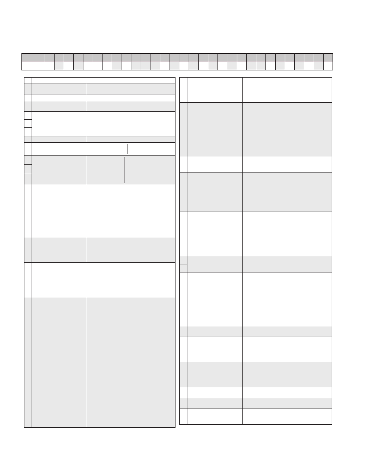
1.2 Model Identication
The model identication number is found on the data sticker. Rating plate located on side panel.
Example M A A 1 0 3 6 A D 0 5 0 C + + + + 1 E A + A 2 1 + + + + + +
Position 1234567891011 12 13 14 15 16 17 18 19 20 21 22 23 24 25 26 27 28 29 30
1Unit Designation/Family M = Marvair Wall Mount
2Energy Efciency Ratio
(EER)
A = 11
G = 10
3Refrigerant Type A = R-410a
4Compressor Type/Quantity 1 = Fixed Speed/Single
2 = 2-Stage/Single
5
Unit Capacity/Nominal
Cooling (BTUH)
018 = 18,000 042 = 42,000
020 = 20,000 048 = 48,000
024 = 24,000 060 = 60,000
030 = 30,000 072 = 72,000
036 = 36,000
6
7
8System Type A = Air Conditioner
9Power Supply
(Volts-Hz-Phase)
A= 208/230-60-1 D= 460-60-3
C= 208/230-60-3 Z= 575-60-3
10
Heat Designation
@ Rated Voltage
000 = No Heat 080 = 8KW
022 = 2.2KW 090 = 9KW
036 = 3.6KW 100 = 10KW
040 = 4KW 120 = 12KW
050 = 5KW 150 = 15KW
060 = 6KW
11
12
13 Ventilation
Conguration
A = Solid Front Door
C = Economizer
D = Motorized Damper w/Pressure Relief
E = Motorized Damper w/Pressure Relief &
Independent Motorized Damper Control
F = No Free Cooling, 100% Emergency
Ventilation Only w/Independent Control
N = Barometric Damper w/15% OSA
Y = Manual Damper w/No Pressure Relief
Z = Manual Damper w/Pressure Relief
+ = None
$ = Special
14 Dehumidication
G = Hot Gas Reheat
R = Electric Reheat
T = Electric Reheat w/Humidity Control
+ = None
$ = Special
15 Controls
A = Power Fail Alarm w/Additional Lockouts
C = 24V EMS Relay Kit
D = 24V EMS Relay Kit w/Factory
Installed T-Stat
E = Factory Installed T-Stat
+ = None
$ = Special
16 Operating Condition
A = Evaporator Freeze Sensor (EFS)
C = EFS w/Hot Gas Bypass
D = Desert Duty
E = Extreme Duty
F = Desert Duty w/Hard Start
G = Desert Duty w/EFS
H = Desert Duty w/Hard Start & EFS
J = Extreme Duty w/Hard Start
K = Extreme Duty w/EFS
M = Extreme Duty w/Hard Start & EFS
N = Hard Start
P = Hard Start w/Low Ambient & CCH
Q = Hard Start w/Low Ambient &
Fan Cycle Control (FCC)
R = Crank Case Heater (CCH)
T = Hard Start w/EFS
U = Hard Start w/Hot Gas Bypass
V = Hard Start w/Low Ambient & CCH & EFS
W = Low Ambient w/CCH
X = Hot Gas Bypass
Y = Low Ambient w/CCH & FCC
Z = Low Ambient w/CCH & EFS
1 = Low Ambient w/FCC
2 = Low Ambient w/FCC & EFS
3 = CCH w/Hot Gas Bypass
+ = None
$ = Special
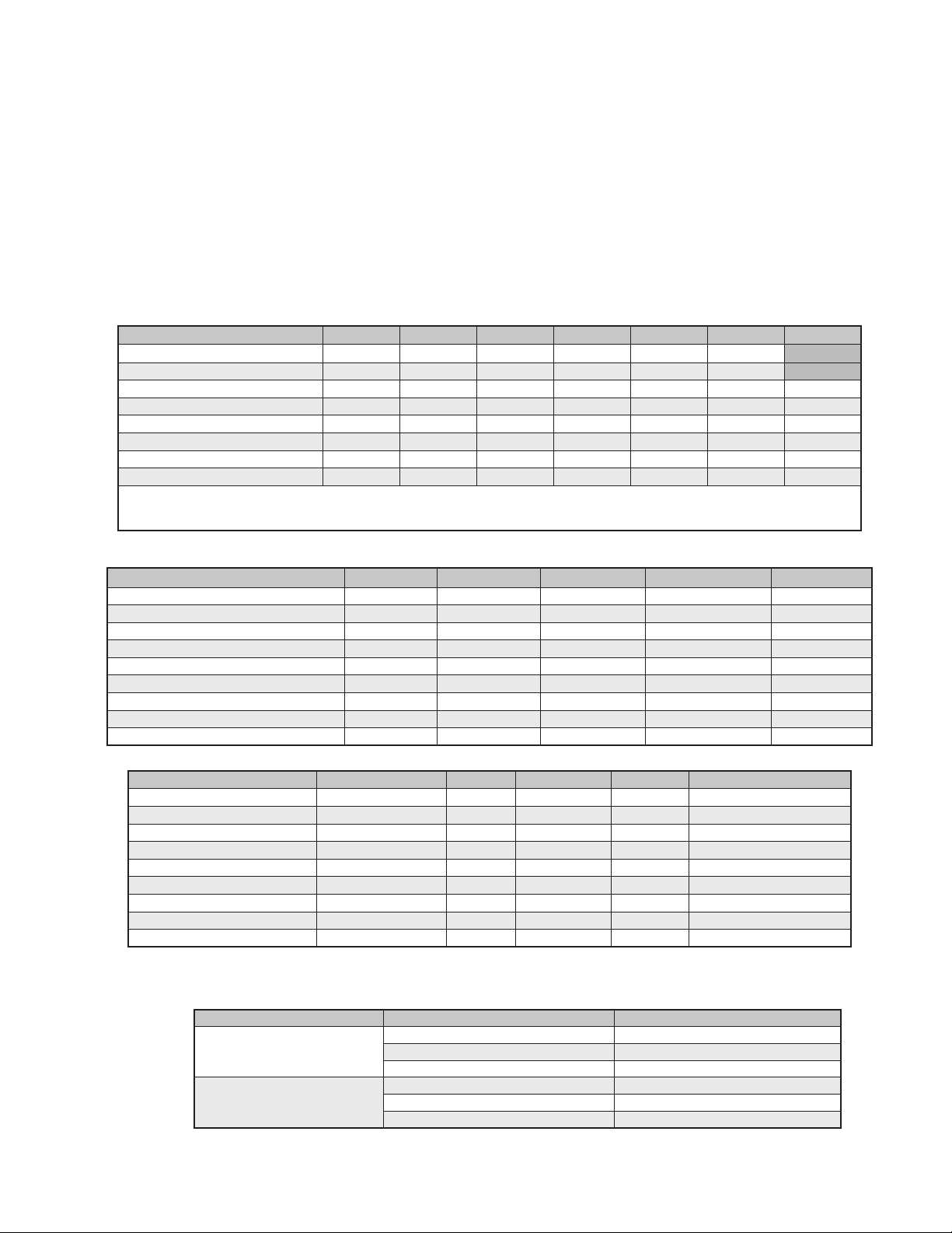
17 Indoor Air Quality Features
D = Dry Bulb Sensor
E = Dry Bulb Sensor w/Dirty Filter
G = Dirty Filter Sensor
+ = None
$ = Special
18 Air Flow
1 = Top Supply/Bottom Return
2 = Center Supply (Reverse)
3 = Bottom Supply/Top Return (Counter)
4 = Top Panel Discharge
5 = Centrifugal Blowers
6 = 3T3
7 = 3T5
8 = 4T2
9 = 4T3
A = 3T2
$ = Special
19 Compressor Location
C= Center - All 6 ton units and above
D= Left Hand - All 31/2 to 5 ton units
E= Right Hand - All 11/2 to 3 ton units
20 Filter Option
A = 2” Pleated (MERV 8, AC/HP-C)
C = 2” Charcoal
D = MERV 11 High Filtration Package
E = MERV 13 High Filtration Package
F = Filter Access Through Return Air Grille
W = Aluminum Washable
+ = None
$ = Special
21 Corrosion Protection
A = Condenser Coil Only
C = Evaporator Coil Only
D = Both Coils Condenser & Evaporator
E = All Coils Cond/Evap/Reheat
F = Coat All
G = Coastal Package & Evaporator Coil
K = Coastal Package
+ = None
$ = Special
22 Engineering Revision
Level
A1
A2
B2
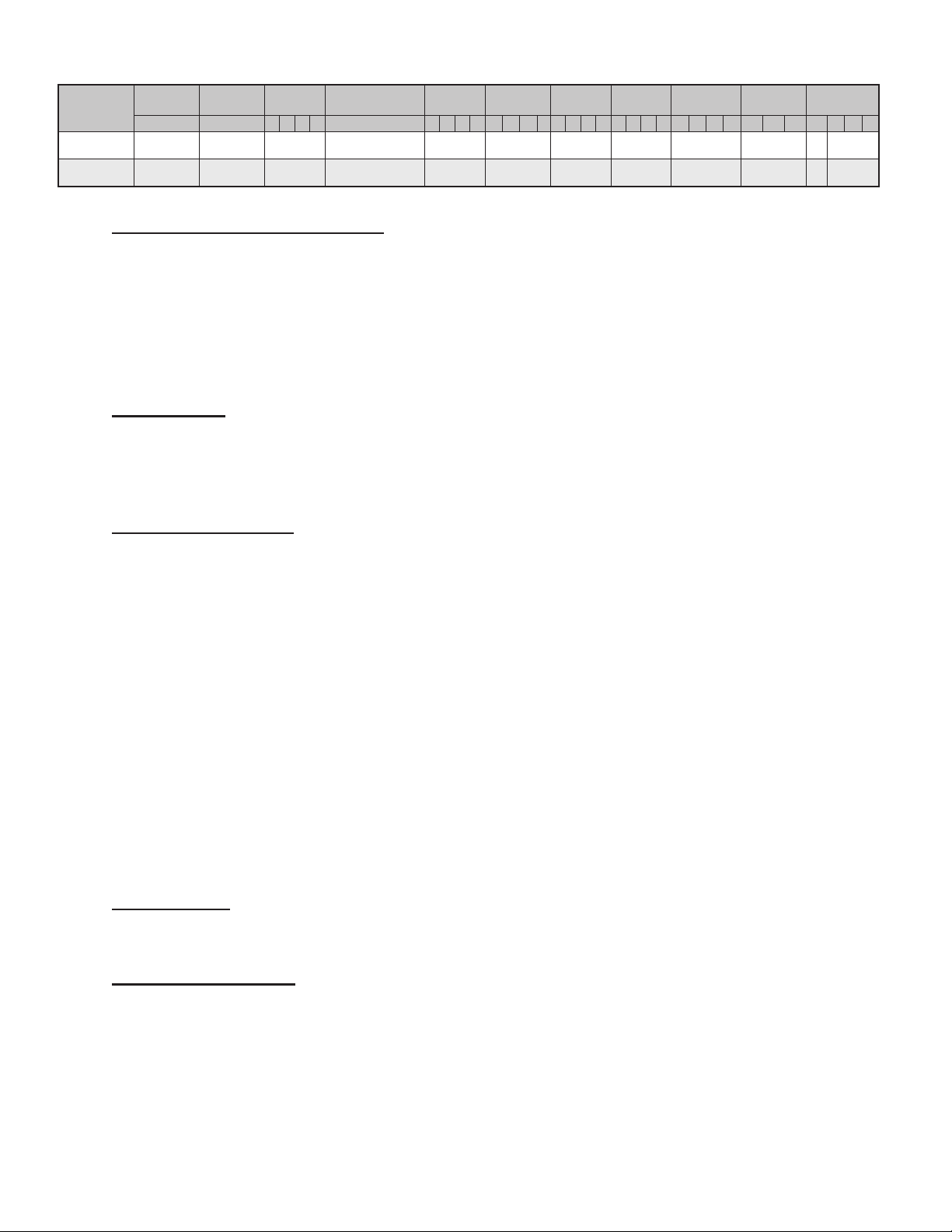
23
24 Cabinet Color
1 = Marvair Beige
2 = Gray
3 = Carlsbad Canyon
4 = White
5 = Stainless Steel Exterior
6 = Dark Bronze
7 = .050 Aluminum Stucco
8 = Mesa Tan
9 = Pebble Gray
A = Stainless Steel - Unit
$ = Custom Color (Powder Coat)
25 Sound Attenuation 2 = Compressor Blanket
+ = None
26 Security Option
A = Lockable Access Plate/Tamper Proof
C = Tamper Proof Screws
D = Lockable Access Plate w/Tamper Proof
+ = None
$ = Special
27 Fastener/Drain Pan Option
A = Stainless Steel Fasteners
C = Stainless Steel Drain Pan
D = Stainless Steel Fasteners & Drain Pan
+ = None
$ = Special
28 Unused + = None
$ = Special
29 Unused + = None
$ = Special
30 Special Variation
+ = None
$ = Special Conguration Not Covered by
Model Nomenclature
Note: Not all options are available with all congurations. Contact your Marvair sales representative for
conguration details and feature compatibility.