Marvel MACR214-SS01B User manual

OWNER’S GUIDE & SERVICE MANUAL
MARVEL UNDERCOUNTER REFRIGERATION
Model: MACR214-SS01B

WELCOME
Welcome to the Marvel Experience!
Thank you for choosing our quality American-built product
to add to your home. We are thrilled to welcome you to
our growing community of Marvel owners, who trust in our
products and our support.
The information in this guide is intended to help you install
and maintain your new Marvel undercounter model to pro-
tect and prolong its lifetime. We encourage you to contact
our Technical Support team at (616) 754-5601 with any
questions.
Got a Marvelous Design?
We would love to see how your Marvel product looks in
its new home. Send us photos at marketing@marvelre-
frigeration.com, and we might feature your Marvel home
design on our website and social media!
Warranty Registration
It is important you send in your warranty registration card
immediately after taking delivery of your appliance or you
can register online at www.marvelrefrigeration.com.
The following information will be
required when registering your
appliance:
Service Number
Serial Number
Date of Purchase
Dealer’s name and address
The service number and serial number can be found on the
serial plate which is located inside the cabinet on the left
side near the top.
Online regis-
tration available at
www.marvelrefriger-
ation.com
XXXXXXXXXXXX
XXXXXXXXXXXX
MARVEL
g
R600A

TABLE OF CONTENTS
Tip: Click on any section below to jump directly there
Safety
Important Safety Instructions
Installation
Unpacking Your Appliance
Electrical
Cutout & Product Dimensions
Installing the anti-tip device
Door Reversal
Installing The Water Supply
Maintenance
Care and Cleaning
Stainless Steel Maintenance
Extended Non-Use
Operating Instructions
Ice Maker Operation
Service
Obtaining Service
Wire Diagram
Product Liability
Warranty Claims
Parts List
Ordering Replacement Parts
R600a Specifications
System Diagnosis Guide
Defrost
Replace Ice Maker
Warranty
3

IMPORTANT SAFETY INSTRUCTIONSIMPORTANT SAFETY INSTRUCTIONS
Important Safety Instructions
Warnings and safety instructions appearing in this guide
are not meant to cover all possible conditions and situa-
tions that may occur. Common sense, caution and care
must be exercised when installing, maintaining or operating
this appliance.
Recognize Safety Symbols,
Words and Labels
NOTE
!CAUTION
CAUTION - Hazards or unsafe practices which could
result in personal injury or property/product damage.
NOTE - Important information to help assure a prob-
lem-free installation and operation.
!WARNING
WARNING - You can be killed or seriously injured
if you do not follow these instructions.
!WARNING
State of California Proposition 65 Warning:
This product contains one or more chemicals known
to the State of California to cause cancer.
!WARNING
State of California Proposition 65 Warning:
This product contains one or more chemicals known
to the State of California to cause birth defects or
other reproductive harm.
!WARNING
WARNING - This unit contains R600a (Isobutane)
which is a fl ammable hydrocarbon. It is safe for regular
use. Do not use sharp objects to expedite defrosting.
Do not damage refrigerant circuit.
4

UNPACKING YOUR APPLIANCE
!WARNING
EXCESSIVE WEIGHT HAZARD
Use two or more people to move product.
Failure to do so can result in personal injury.
Remove Interior Packaging
Your appliance has been packed for shipment with all parts
that could be damaged by movement securely fastened.
Remove internal packing materials and any tape holding in-
ternal components in place. The owners manual is shipped
inside the product in a plastic bag along with the warranty
registration card and other accessory items.
Important
Keep your carton and packaging until your appliance has
been thoroughly inspected and found to be in good condi-
tion. If there is damage, the packaging will be needed as
proof of damage in transit. Afterwards, please dispose of all
items responsibly.
Note to Customer
This merchandise was carefully packed and thoroughly
inspected before leaving our plant. Responsibility for its
safe delivery was assumed by the retailer upon acceptance
of the shipment. Claims for loss or damage sustained in
transit must be made to the retailer.
DO NOT RETURN DAMAGED MERCHANDISE TO THE
MANUFACTURER - FILE THE CLAIM WITH THE RETAIL-
ER.
NOTE
!WARNING
WARNING - Dispose of the plastic bags which can
be a suff ocation hazard.
!CAUTION
!WARNING
WARNING - Help Prevent Tragedies
Child entrapment and suff ocation are not problems of
the past. Junked or abandonded refrigerators are still
dangerous, even if they sit outside for “just a few hours”.
If you are getting rid of your old refrigerator, please fol-
low the instructions below to help prevent accidents.
Before you throw away your old refrigerator or freezer:
• Take off the doors or remove the drawers.
• Leave the shelves in place so children may not
• easily climb inside.
If the appliance was shipped, handled or stored in other
than an upright position for any period of time, allow the ap-
pliance to sit upright for a period of at least 24 hours before
plugging in. This will assure oil returns to the compressor.
Plugging the appliance in immediately may cause damage
to internal parts.
5

ELECTRICAL
NOTE
Electrical Shock Hazard
• Do not use an extension cord with this appliance.
They can be hazardous and can degrade product
performance.
• This appliance should not, under any circum-
stances, be installed to an un-grounded electrical
supply. Do not remove the grounding prong from
the power cord.
• Do not use an adapter.
• Do not splash or spray water from a hose on
the appliance. Doing so may cause an electrical
shock, which may result in severe injury or death.
!WARNING
Ground Fault Circuit Interrupters (GFCI) are prone to nui-
sance tripping which will cause the appliance to shut down.
GFCI’s are generally not used on circuits with power equip-
ment that must run unattended for long periods of time, un-
less required to meet local building codes and ordinances.
Electrical Connection
A grounded 115 volt, 15 amp dedicated circuit is required.
This product is factory equipped with a power supply
cord that has a three-pronged, grounded plug. It must be
plugged into a mating grounding type receptacle in accor-
dance with the National Electrical Code and applicable
local codes and ordinances. If the circuit does not have a
grounding type receptacle, it is the responsibility and obli-
gation of the customer to provide the proper power supply.
The third-ground prong should not, under any circumstanc-
es, be cut or removed.
Do not remove
ground prong
6

CUTOUT AND PRODUCT DIMENSIONS
Cutout and Product Dimensions
Prepare Site
Your Marvel product has been designed for either free-
standing or built-in installation. When built-in, your unit
does not require additional air space for top, sides, or rear.
However, the front grille must NOT be obstructed, and
clearance is required for an electrical connection in the
rear.
Unit can NOT be installed behind a closed cabinet door.
Cutout Dimensions
´&XWRXWZLGWKVXႈFLHQWLIGRRUSURWUXGHVEH\RQG
adjacent cabinetry
Product Dimensions
Rear
!CAUTION
Typical
Counter
Height
34-ȟΞ"
(870 mm)
to
35-ȟΞ"
(892 mm)
Cutout
Height
24-ΓȟΞ"
(632 mm)
Filler Panel (Not Provided by U-Line) –
May Be Added Above or Below Unit
to Enclose for a Built-In Look
14"
(356 mm)
21-1/2"
(546 mm)
Minimum
See Electrical
6SHFLɟFDWLRQV
for Power Supply
4"
(102 mm)
7"
(178 mm)
Preferred location
for water line and
electrical outlet is
in adjacent cabinet.
5/8"
(16 mm)
1 ⁄”
(32 mm)
3 ⁄”
(32 mm)
Water Line 11
½
”
(292 mm)
2”
(51 mm)
Power Cord
Front
Top
Side
13 ⁄”
(352 mm)
8 ⁄”
(227 mm)
10”
(254 mm)
24 ¾”
(629 m
m
1 ⁄”
(48 mm)
15 ⁄”
(392 mm)
14 ⁄”
(371 mm)
18 ⁄”
(478 mm)
16 ⁄”
(430 mm)
1 ⁄“ (41mm)
11 ⁄”
(302 mm
7

INSTALLING THE ANTI-TIP DEVICE
Anti-Tip Bracket
1. Slide unit out so screws on top of unit are easily
accessible.
2. Remove the two screws from the opposite side of the
hinge assembly using a T-25 Torx driver (see below).
Place bracket over holes and attach to unit with two
screws removed in step 2 using a T-25 Torx driver.
Tighten screws fully.
Gently push unit into position. Be careful not to entangle
the electrical cord or water line, if applicable.
Check to be sure the unit is level from front to back and
side to side. Make any necessary adjustments. The
unit’s top surface should be approximately ¹»” (3 mm)
below the countertop.
Secure bracket into adjoining surface.
8

DOOR REVERSAL
Door Alignment and Adjustment
Align and adjust the door if it is not level or is not sealing
properly. If the door is not sealed, the unit may not cool
properly, or excessive frost may form in the interior.
3URSHUO\DOLJQHGWKHGRRU¶VJDVNHWVKRXOGEH¿UPO\LQ
contact with the cabinet all the way around the door (no
gaps). Carefully examine the door’s gasket to ensure that
LWLV¿UPO\LQFRQWDFWZLWKWKHFDELQHW$OVRPDNHVXUHWKH
door gasket is not pinched on the hinge side of the door.
To align and adjust the door:
1. Loosen (do not remove) top and bottom hinge screws
using a Torx T-25 screwdriver on the top and a 1/4”
socket on the bottom.
2. Align door squarely with cabinet.
3. 0DNHVXUHJDVNHWLV¿UPO\LQFRQWDFWZLWKFDELQHWDOO
the way around the door (no gaps).
4. Tighten bottom hinge screws.
5. Tighten top hinge screws.
Reversing the Door
Location of the unit may make it desirable to mount the
door on the opposite side of the cabinet.
The hinge hardware will be removed and reinstalled on the
opposite side of the cabinet.
Remove arrow clips:
1. :LWKDSXGG\NQLIHRURWKHUÀDWWRROJHQWO\SU\HDFK
arrow clip from hinge mounting holes.
2. Set aside arrow clips to be reused on the opposite side.
To Reverse the Door
Remove top hinge and door:
1. Hold door to keep it from falling.
2. Remove top hinge from cabinet using a Torx T-25
screwdriver to remove three screws.
3. 5HPRYHGRRUE\WLOWLQJIRUZDUGDQGOLIWLQJGRRURႇ
bottom hinge. Retain shoulder washers; they will be
reused.
4. Remove three screws from hinge holes on the opposite
side (stainless steel model only).
5. For stainless steel model, install three screws into
holes where the hinge was removed; black or white
models, install 3 arrow clips.
Move bottom hinge:
1. Remove grille (see GRILLE INSTALLATION).
2. Remove two hinge screws
3. Remove corresponding screws on opposite side of
cabinet.
4. Install bottom hinge on opposite side.
NOTE
Arrow Clip
Hinge screws
Remove two
hinge screws
Center Screw
9

DOOR REVERSAL
Install top hinge:
1. 5HPRYHSLYRWVFUHZIURPKLQJHÀLSKLQJHRYHUDQG
install the pivot screw in the same hole from the
opposite surface.
2. Rotate door 1800, and set door onto the bottom hinge.
3. Align edge of top hinge with the outer edge of the unit.
4. Install hinge onto top of door.
5. Install three screws and tighten.
Install grille
Align and adjust the door:
Align and adjust the door (see Door Alignment and
Adjustment)
Top Hinge
Right Side
Top Hinge
Left Side
Pivot
Screw
10

INSTALLING THE WATER SUPPLY
Prepare Plumbing
Plumbing installation must observe all state and local
codes. All water and drain connections MUST BE made by
DOLFHQVHGTXDOL¿HGSOXPELQJFRQWUDFWRU)DLOXUHWRIROORZ
recommendations and instructions may result in damage
and/or harm.
Water Supply Connection
:KHQFRQQHFWLQJWKHZDWHUVXSSO\SOHDVHQRWHWKH
IROORZLQJ
•%HIRUHLQVWDOOLQJWKHXQLWDQGFRQQHFWLQJWRWKHFROG
ZDWHUVXSSO\UHYLHZWKHORFDOSOXPELQJFRGHV
•7KHZDWHUSUHVVXUHVKRXOGEHEHWZHHQDPLQLPXPRI
DQGDPD[LPXPRISVLDQGN3D
•:DWHUKDVOHVVWKDQPJ/SSPWRWDOGLVVROYHG
VROLGVDQGKDUGQHVVOHYHOEHORZPJ/SSP²LH
EHORZJUDLQVSHUJDOORQ&KHFNE\XVLQJ7'6PHWHU
RUFRQVXOWLQJZLWKORFDOZDWHUFRPSDQ\
•7'6DQGRUZDWHUKDUGQHVVDERYHWKHVHOLPLWVVKRXOG
be treated with a reverse osmosis system or other
¿OWUDWLRQV\VWHP
•6RIWHQHGZDWHULVQRWUHFRPPHQGHGDVLWPD\UHVXOWLQ
VRIWHULFHWKDQGHVLUHG
•&RQQHFWLRQWRWKHZDWHUPDLQLVPDGHZLWKKRVHVHW
only.
•+RVHVHWPXVWEHQHZQRWUHXVHGDQGLQFRPSOLDQFH
ZLWK,(&
•7KHZDWHUOLQH0867KDYHDVKXWRႇYDOYHLQWKH
VXSSO\OLQH
•7KHZDWHUOLQHVKRXOGEHORRSHGLQWRFRLOV7KLVZLOO
DOORZWKHXQLWWREHUHPRYHGIRUFOHDQLQJDQGVHUYLFLQJ
0DNHFHUWDLQWKDWWKHWXELQJLVQRWSLQFKHGRUGDPDJHG
during installation.
!CAUTION 'RQRWXVHDQ\SODVWLFZDWHUVXSSO\OLQH7KHOLQHLVXQGHU
SUHVVXUHDWDOOWLPHV3ODVWLFPD\FUDFNRUUXSWXUHZLWKDJH
DQGFDXVHGDPDJHWR\RXUKRPH'RQRWXVHWDSHRUMRLQW
FRPSRXQGZKHQDWWDFKLQJDEUDLGHGÀH[LEOHZDWHUVXSSO\
OLQHWKDWLQFOXGHVDUXEEHUJDVNHW7KHJDVNHWSURYLGHV
DQDGHTXDWHVHDO±RWKHUPDWHULDOVFRXOGFDXVHEORFNDJH
RIWKHYDOYH)DLOXUHWRIROORZUHFRPPHQGDWLRQVDQG
LQVWUXFWLRQVPD\UHVXOWLQGDPDJHDQGRUKDUPÀRRGLQJRU
YRLGWKHSURGXFWZDUUDQW\8VHQHZKRVHVHW'RQRWUHXVH
old hose set.
7XUQRႇZDWHUVXSSO\DQGGLVFRQQHFWHOHFWULFDOVXSSO\WR
XQLWSULRUWRLQVWDOODWLRQ8VHFDXWLRQZKHQKDQGOLQJEDFN
SDQHO7KHHGJHVFRXOGEHVKDUS
!CAUTION
!CAUTION
11

INSTALLING THE WATER SUPPLY
7XUQRႇZDWHUVXSSO\DQGGLVFRQQHFWHOHFWULFDOVXSSO\
WRSURGXFWSULRUWRDWWHPSWLQJLQVWDOODWLRQ
2. 5HPRYHWKHEDFNSDQHO
7KUHDGZDWHUOLQHWKURXJKEDFNSDQHOKROHZLWK
EXVKLQJ
4. Locate water valve inlet and connect to valve.
5. 7XUQRQZDWHUVXSSO\DQGFKHFNIRUOHDNV
5HLQVWDOOEDFNSDQHO
3
4
12

Ice Cube Thickness Adjustment
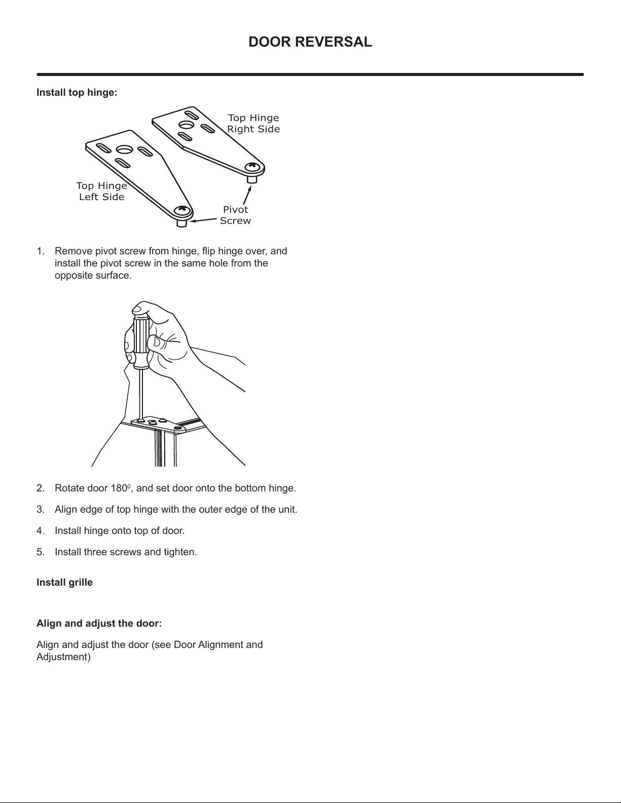
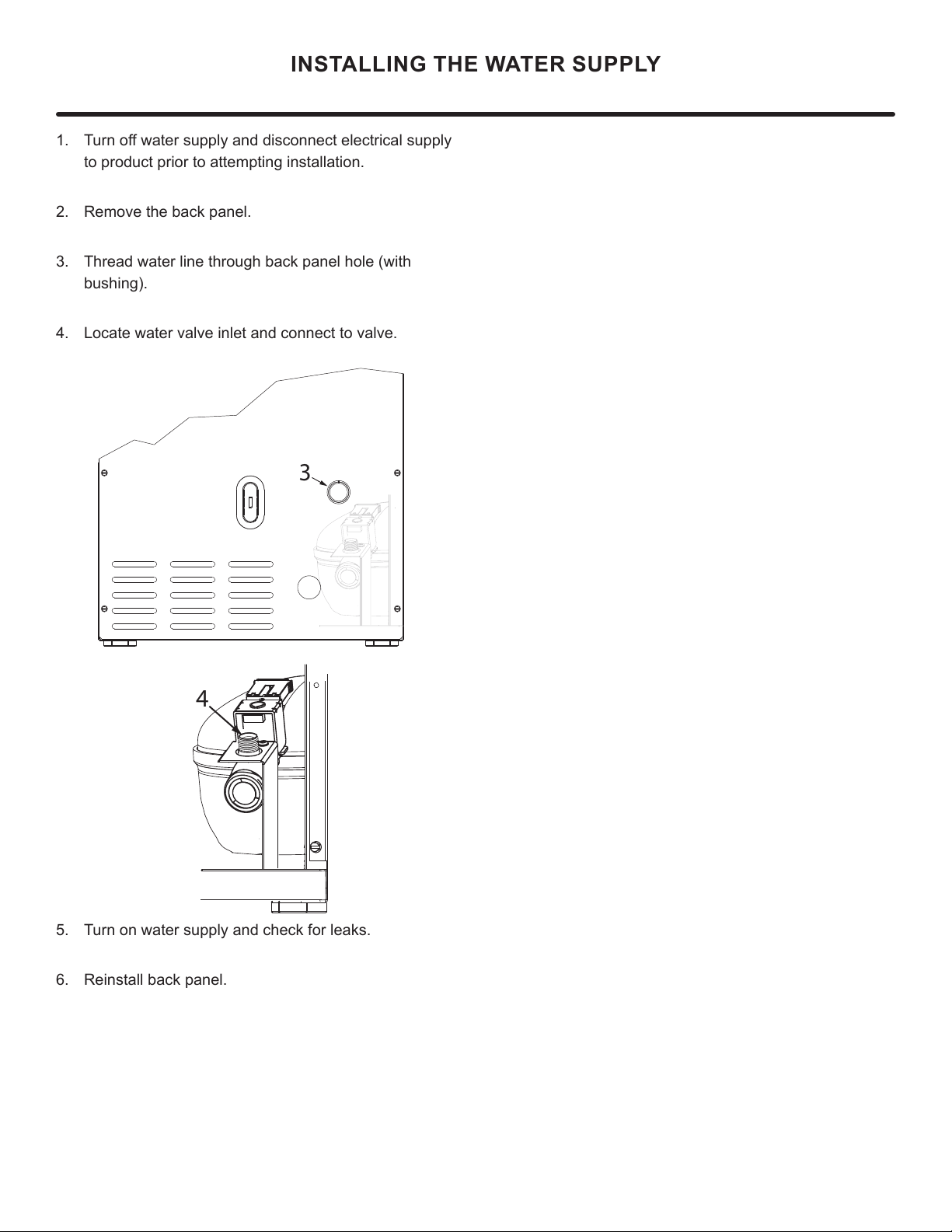
Interval - As Required.
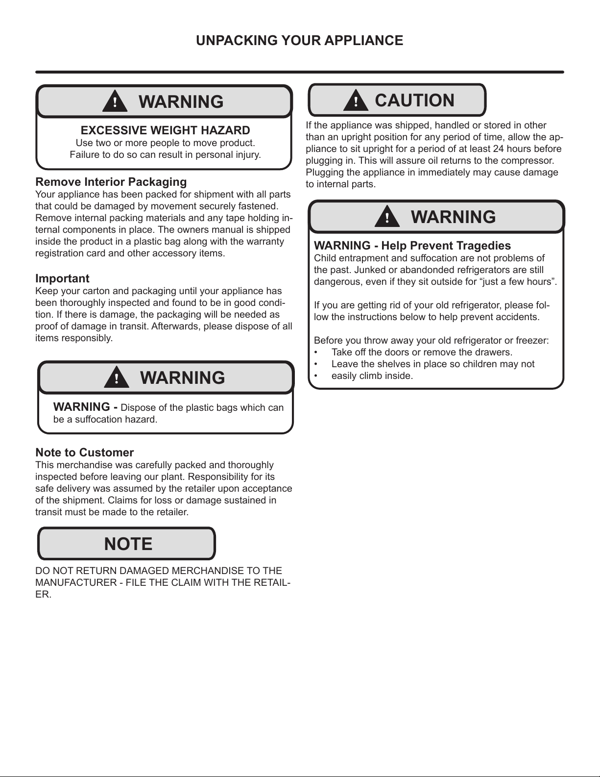
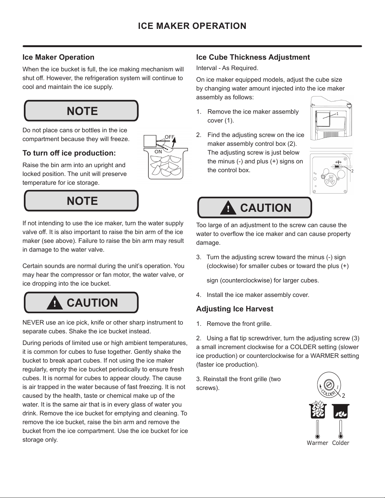
On ice maker equipped models, adjust the cube size
by changing water amount injected into the ice maker
assembly as follows:
1. Remove the ice maker assembly
cover (1).
2. Find the adjusting screw on the ice
maker assembly control box (2).
The adjusting screw is just below
the minus (-) and plus (+) signs on
the control box.
Too large of an adjustment to the screw can cause the
ZDWHUWRRYHUÀRZWKHLFHPDNHUDQGFDQFDXVHSURSHUW\
damage.
3. Turn the adjusting screw toward the minus (-) sign
(clockwise) for smaller cubes or toward the plus (+)
sign (counterclockwise) for larger cubes.
4. Install the ice maker assembly cover.
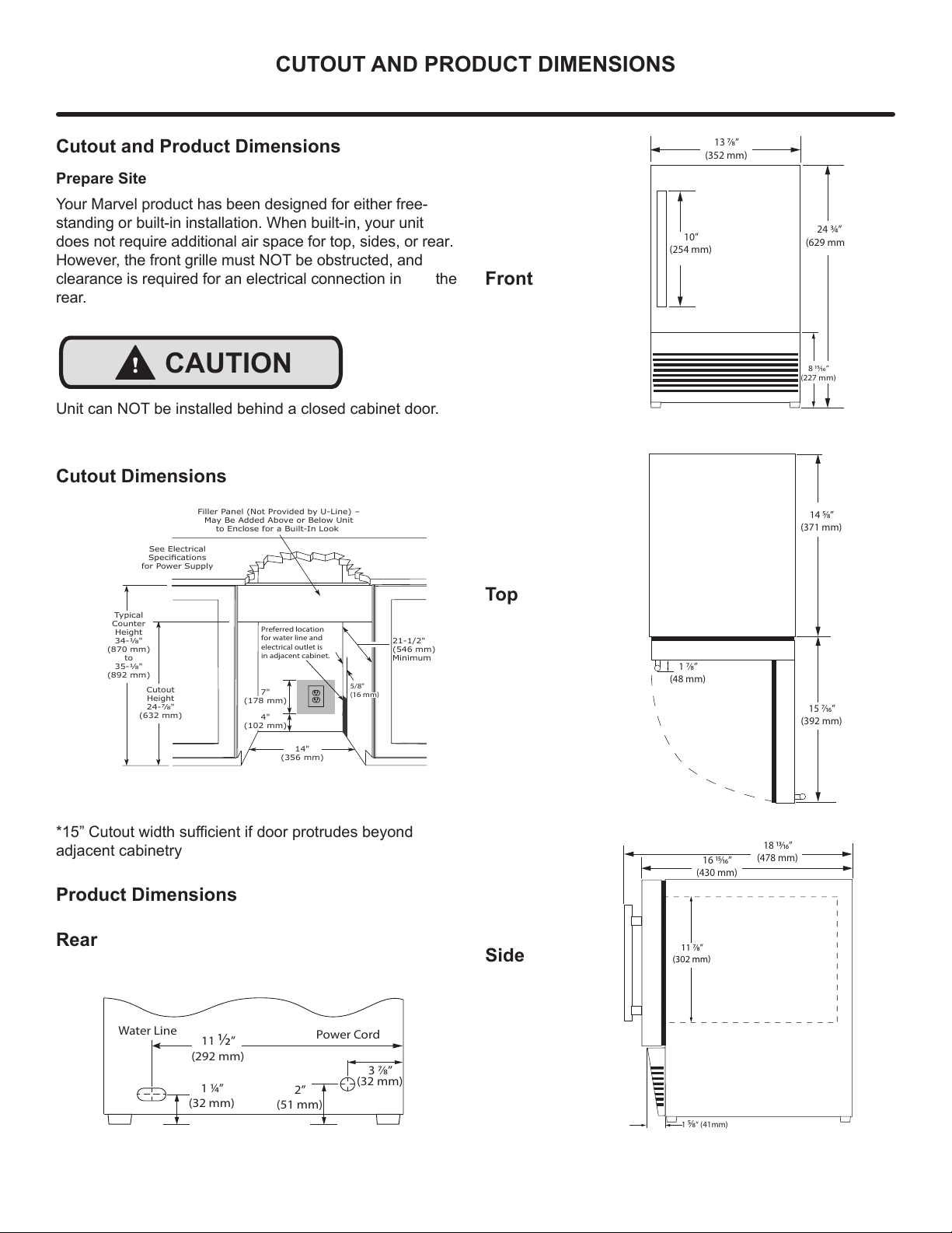
Adjusting Ice Harvest
1. Remove the front grille.
8VLQJDÀDWWLSVFUHZGULYHUWXUQWKHDGMXVWLQJVFUHZ
a small increment clockwise for a COLDER setting (slower
ice production) or counterclockwise for a WARMER setting
(faster ice production).
3. Reinstall the front grille (two
screws).
Ice Maker Operation
When the ice bucket is full, the ice making mechanism will
VKXWRႇ+RZHYHUWKHUHIULJHUDWLRQV\VWHPZLOOFRQWLQXHWR
cool and maintain the ice supply.
Do not place cans or bottles in the ice
compartment because they will freeze.
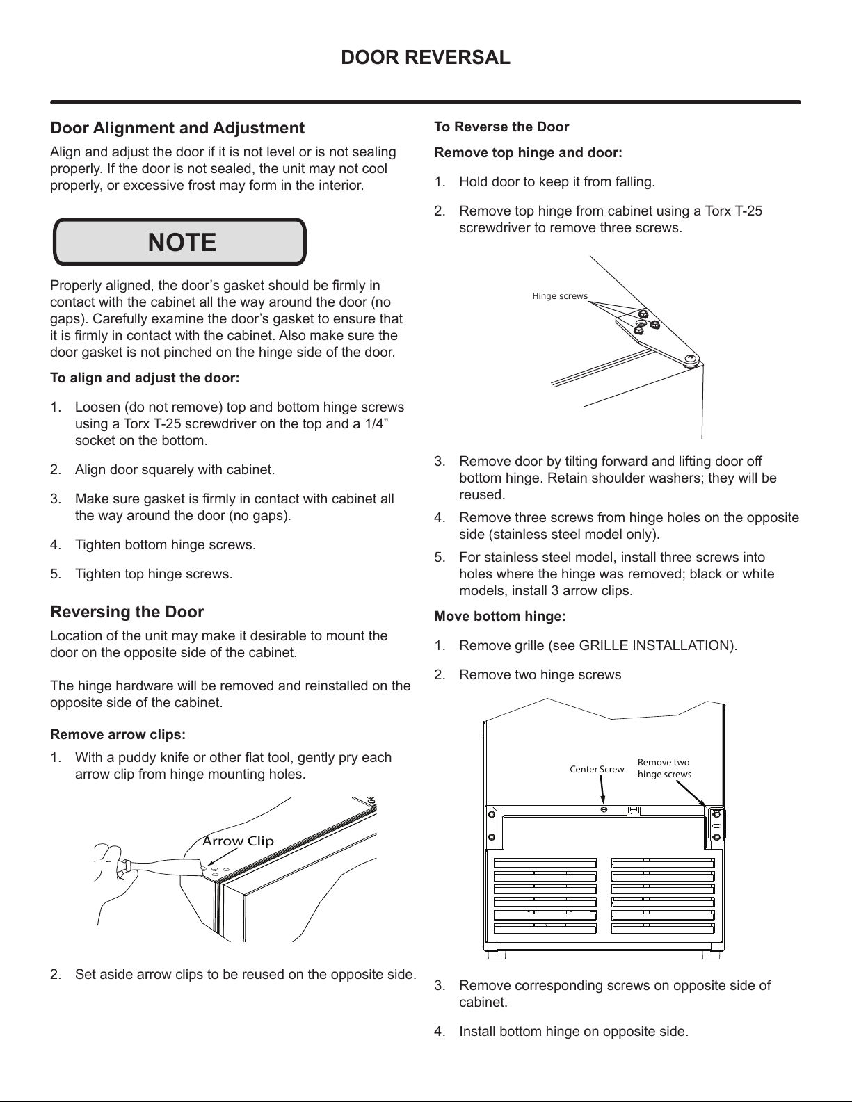
7RWXUQRႇLFHSURGXFWLRQ
Raise the bin arm into an upright and
locked position. The unit will preserve
temperature for ice storage.
If not intending to use the ice maker, turn the water supply
YDOYHRႇ,WLVDOVRLPSRUWDQWWRUDLVHWKHELQDUPRIWKHLFH
maker (see above). Failure to raise the bin arm may result
in damage to the water valve.
Certain sounds are normal during the unit’s operation. You
may hear the compressor or fan motor, the water valve, or
ice dropping into the ice bucket.
NEVER use an ice pick, knife or other sharp instrument to
separate cubes. Shake the ice bucket instead.
During periods of limited use or high ambient temperatures,
it is common for cubes to fuse together. Gently shake the
bucket to break apart cubes. If not using the ice maker
regularly, empty the ice bucket periodically to ensure fresh
cubes. It is normal for cubes to appear cloudy. The cause
is air trapped in the water because of fast freezing. It is not
caused by the health, taste or chemical make up of the
water. It is the same air that is in every glass of water you
drink. Remove the ice bucket for emptying and cleaning. To
remove the ice bucket, raise the bin arm and remove the
bucket from the ice compartment. Use the ice bucket for ice
storage only.
ICE MAKER OPERATION
NOTE
NOTE
!CAUTION
!CAUTION
C
O
L
D
E
R
Warmer Colder
13

CARE AND CLEANING
Exterior Cleaning
Stainless door panels, handles and frames can discolor
when exposed to chlorine gas, pool chemicals, saltwater or
cleaners with bleach.
Keep your stainless unit looking new by cleaning with a
good quality all-in-one stainless steel cleaner and polish
monthly. For best results use Claire®Stainless Steel
Polish and Cleaner. Comparable products are acceptable.
Frequent cleaning will remove surface contamination that
could lead to rust. Some installations may require cleaning
weekly.
Do not clean with steel wool pads.
Do not use stainless steel cleaners or polishes on any
glass surfaces.
Clean any glass surfaces with a non-chlorine glass cleaner.
'RQRWXVHFOHDQHUVQRWVSHFL¿FDOO\LQWHQGHGIRUVWDLQOHVV
steel on stainless steel surfaces (this includes glass, tile,
and counter cleaners).
If any surface discoloring or rusting appears, clean it
quickly with Bon-Ami®or Barkeepers Friend Cleanser®and
a nonabrasive cloth. Always clean with the grain. Always
¿QLVKZLWK&ODLUH®Stainless Steel Polish and Cleaner or
comparable product to prevent further problems.
Using abrasive pads such as ScotchBrite™ will
cause the graining in the stainless steel to
become blurred.
Rust not cleaned up promptly can penetrate the
surface of the stainless steel and complete
removal of the rust may not be possible.
Integrated Models
To clean integrated panels, use household cleaner per the
cabinet manufacturer’s recommendations.
Interior Cleaning
Disconnect power to the unit.
Clean the interior and all removed components using a mild
nonabrasive detergent and warm solution applied with a soft
sponge or non-abrasive cloth.
Rinse the interior using a soft sponge and clean water.
Do not use any solvent-based or abrasive cleaners. These
types of cleaners may transfer taste and/or odor to the
interior products and damage or discolor the interior.
Defrosting
This unit is a manual defrost model and will require
occasional defrosting. When there is build-up of 1/4”
(6 mm) or more of frost, manually defrost the unit.
DO NOT use an ice pick or other sharp instrument to help speed
up defrosting. These instruments can puncture the inner lining
or damage the cooling unit. DO NOT use any type of heater to
defrost. Using a heater to speed up defrosting can cause personal
injury and damage to the inner lining.
!CAUTION
14

&$5($1'&/($1,1*
To Defrost
1. Disconnect power to the unit.
2. Remove ice bucket and discard ice.
3. Place towel or other absorbent material on bottom of
ice bin.
4. Fill the ice bucket half full with warm, not hot water.
This will help the unit defrost faster.
5. Place the ice bucket back into the unit on top of the
towel or other absorbent material.
6. Prop the door in an open position (2 in. [50 mm] mini-
mum).
7. After about 1 hour remove the ice bin and discard
water.
8. Allow the frost to melt naturally.
9. After the frost melts completely clean the interior and
all removed components. (See Interior Cleaning).
DO NOT clean ice bucket using a dishwasher. The bucket
is not dishwasher safe and will be damaged.
10. When the interior is dry, reconnect power and turn unit
on.
7RVDIHJXDUGDJDLQVWFRQWDPLQDWHVLQLFHGLVFDUG¿UVWWKUHH
batches of ice after defrosting.
NOTE
NOTE
Cleaning Condenser
Interval - every six months
7RPDLQWDLQRSHUDWLRQDOHႈFLHQF\NHHSWKHIURQWJULOOHIUHH
of dust and lint, and clean the condenser when necessary.
Depending on environmental conditions, more or less
frequent cleaning may be necessary.
Do not use any type of cleaner on the condenser unit.
Condenser may be cleaned using a vacuum, soft brush, or
compressed air.
1. Remove the grille. See GRILLE INSTALLATION).
2. Clean the condenser coil using a soft brush or vacuum
cleaner.
3. Install the grille.
!WARNING
WARNING - Disconnect electric power to the unit
before cleaning the condenser.
NOTE
CONDENSER
15

STAINLESS STEEL MAINTENANCE
Background
Stainless steel does not stain, corrode, or rust as easily as
ordinary steel, but it is not stain or corrosion proof. Stain-
less steels can discolor or corrode if not maintained prop-
erly.
amount of chromium present. It is this chromium that
surface can be damaged or contaminated, which may
result in discoloration, staining, or corrosion of the base
metal.
Care & Cleaning
Routine cleaning of the stainless steel surfaces will serve to
greatly extend the life of your product by removing contami-
nants. This is especially important in coastal areas which
can expose the stainless to severe contaminants such as
It is strongly recommended to periodically inspect and thor-
oughly clean crevices, weld points, under gaskets, rivets,
bolt heads, and any locations where small amounts of liquid
could collect, become stagnant, and concentrate contami-
nates. Additionally, any mounting hardware that is showing
signs of corrosion should be replaced.
Frequency of cleaning will depend upon the installation
location, environmental, and usage conditions.
Choosing a Cleaning Product
The choice of a proper cleaning product is ultimately that
of the consumer, and there are many products from which
to choose. Depending upon the type of cleaning and the
degree of contamination, some products are better than
others.
cleaning of most stainless steel products is to give the sur-
faces a brisk rubbing with a soft cloth soaked in warm water
and a gentle detergent, or mild mixture of ammonia. Rub-
bing should, to the extent possible, follow the polish lines of
the steel, and always insure thorough rinsing after cleaning.
Although some products are called "stainless steel clean-
ers," some may contain abrasives which could scratch the
and some many contain chlorine bleach which will dull,
tarnish or discolor the surface if not completely removed.
After the stainless surfaces have been thoroughly cleaned,
a good quality car wax may be applied to help maintain the
Stainless steel products should never be installed, or stored
in close proximity to chlorine chemicals.
Whichever cleaning product you chose, it should be used
in strict accordance with the instructions of the cleaner
manufacturer.
NOTE
16

EXTENDED NON-USE
Extended Non-Use
Vacation/Holiday - Prolonged Shutdown
The following steps are recommended for periods of
extended non-use:
1. Remove all consumable content from the unit.
2. Disconnect the power cord from its outlet/socket and
leave it disconnected until the unit is returned to service.
3. 7XUQRႇWKHZDWHUVXSSO\
4. If ice is on the evaporator, allow ice to thaw naturally.
5. Clean and dry the interior of the cabinet. Ensure all
water has been removed from the unit.
6. Disconnect the water and drain line (if applicable)
making sure all water is removed from the lines.
7. The door must remain open to prevent formation of
mold and mildew. Open door a minimum of 2” (50 mm)
to provide the necessary ventilation.
Winterization
If the unit will be exposed to temperatures of 40°F (5°C)
or less, the steps above must be followed. In addition,
P60 drain pumps in clear ice machines must be drained
according to the following procedure:
1. Remove the drain pump from the ice machine.
2. Drain the water in the pump’s reservoir by turning the
pump upside down and allowing the water to drain
WKURXJKWKHSXPS¶VLQOHWDQGYHQWWXEH¿WWLQJV
3. After water is drained, reinstall the drain pump and
reattach all connections.
For questions regarding winterization, please call Marvel at
616.754.5601.
Damage caused by freezing temperatures is not covered by
the warranty. Do not put anti-freeze in your unit.
!CAUTION
17

If Service is Required:
• If the product is within the rst year warranty period
please contact your dealer or call Marvel Customer
Service at 616.754.5601 for directions on how to obtain
warranty coverage in your area.
• If the product is outside the rst year warranty period,
Marvel Customer Service can provide recommenda-
tions of service centers in your area. A listing of autho-
rized service centers is also available at www.marvelre-
frigeration.com under the service and support section.
• In all correspondence regarding service, be sure to
give the service number, serial number, and proof of
purchase.
• Try to have information or description of nature of the
problem, how long the appliance has been running, the
room temperature, and any additional information that
may be helpful in quickly solving the problem.
• Table "B" is provided for recording pertinent information
regarding your product for future reference.
For Your Records
Date of Purchase
Dealer’s name
Dealer’s Address
Dealer’s City
Dealer’s State
Dealer’s Zip Code
Appliance Serial Number
Appliance Service Number
Date Warranty Card Sent (Must
be within 10 days of purchase).
Table B
OBTAINING SERVICE
18

MANUAL CONTROL ICEMAKER & COMBO
ROCKER
SWITCH
COND
FAN
WATER
VALVE
SEE COMPRESSOR
DIAGRAMS
BROWN
BLUE
BLUE
WHITE
BLACK
BLACK
WHITE
BIN
SW
NO NC
C
WATER
SW
NC NO
C
HOLD
SW
NO NC
C
CAM
3 RPM
MOTOR
LIMIT
SW
MOLD HEATER
YELLOW
RED
WHITE
BROWN
BLACK
RED
YELLOW
BROWN
BLACK
BROWN
ORANGE
OR BLUE
BLACK
OR BLUE
OR
ALL OTHER MODELS
ICEMAKER
BI1215 ONLY
CONTROL
GROUND:
GREEN or GREEN W/ YELLOW 115
VOLT
PLUG
220-240 VOLT
PLUG
BLACK-HOT
(SMOOTH)
BLACK-NEUTRAL
(RIBBED)
BLACK
WHITE
RED
YELLOW
BROWN
WHITE
BLACK
1
36
4
4
1
5
3
2
6
4
1
5
3
2
6
NEUTRAL
HOT
RELAY
EMBRACO
COMPRESSOR
GREEN or
GREEN W/ YELLOW
GROUND:
OVERLOAD
19

Product Liability
E
V
G
The original refrigeration experts since 1892.
20
Table of contents
Other Marvel Refrigerator manuals

Marvel
Marvel 6SBAR-BN User manual

Marvel
Marvel MPBV415 User manual

Marvel
Marvel MOCP215-SS01B Application guide

Marvel
Marvel MPBV415 User manual

Marvel
Marvel MOCL215-SS01B User manual

Marvel
Marvel 6OBAR-SS-F User manual

Marvel
Marvel MACL215-IS01A User manual

Marvel
Marvel ML15BC Manual

Marvel
Marvel 30ARM Manual

Marvel
Marvel 61RF-BB-F User manual

Marvel
Marvel 6CiM Guide

Marvel
Marvel MARE124SG31A User manual

Marvel
Marvel 61WC-BB-G Guide

Marvel
Marvel SPARTAN IRONWORKER User manual

Marvel
Marvel 3SBARE-BB-G User manual

Marvel
Marvel MPRE424-SS31A User manual

Marvel
Marvel 30ARM-BB-F Manual

Marvel
Marvel MOCP215 User manual

Marvel
Marvel MLCR215 User manual

Marvel
Marvel MPRE424-SG31A User manual