TABLE OF CONTENTS
3
cod. G19503950 3
Operating
How to choose between sickle bars...............30
Service Machine Safely
Practice safe maintenance.............................31
Wear appropriate clothing ..............................31
Stay clear of rotating drivelines ......................31
Maintenance...................................................31
Hazard bar......................................................32
Service
/XEUL¿FDWLRQ ....................................................33
Routine maintenance......................................33
Every 2 work hours.........................................33
Wear-proof skids (optional) ............................33
Every 8 work hours.........................................33
Every 50 work hours.......................................33
Periodically (6 months)...................................34
After each mowing .........................................34
Cleaning and oiling the sickle bar..................35
Storage ..........................................................35
Checking the clearance tolerance..................36
Extra maintenance..........................................38
Replacement of section-holding bar...............38
Replacement of sections................................38
Replacement of tooth-holding bar (riveted)....39
Replacement of tooth (riveted).......................39
Replacement of bar holding removable tooth 39
Replacement of removable tooth....................39
Replacing the anti-vibration yokes..................40
Replacement of belts......................................40
Replacement of pulleys..................................40
Transport on road
Transport on road ..........................................41
Demolition and disposal
Demolition and disposal ................................42
Assembly
Assembly........................................................43
Spare parts
Spare parts.....................................................51
Warranty
Warranty.........................................................68
Warranty for replacement parts......................69
Description
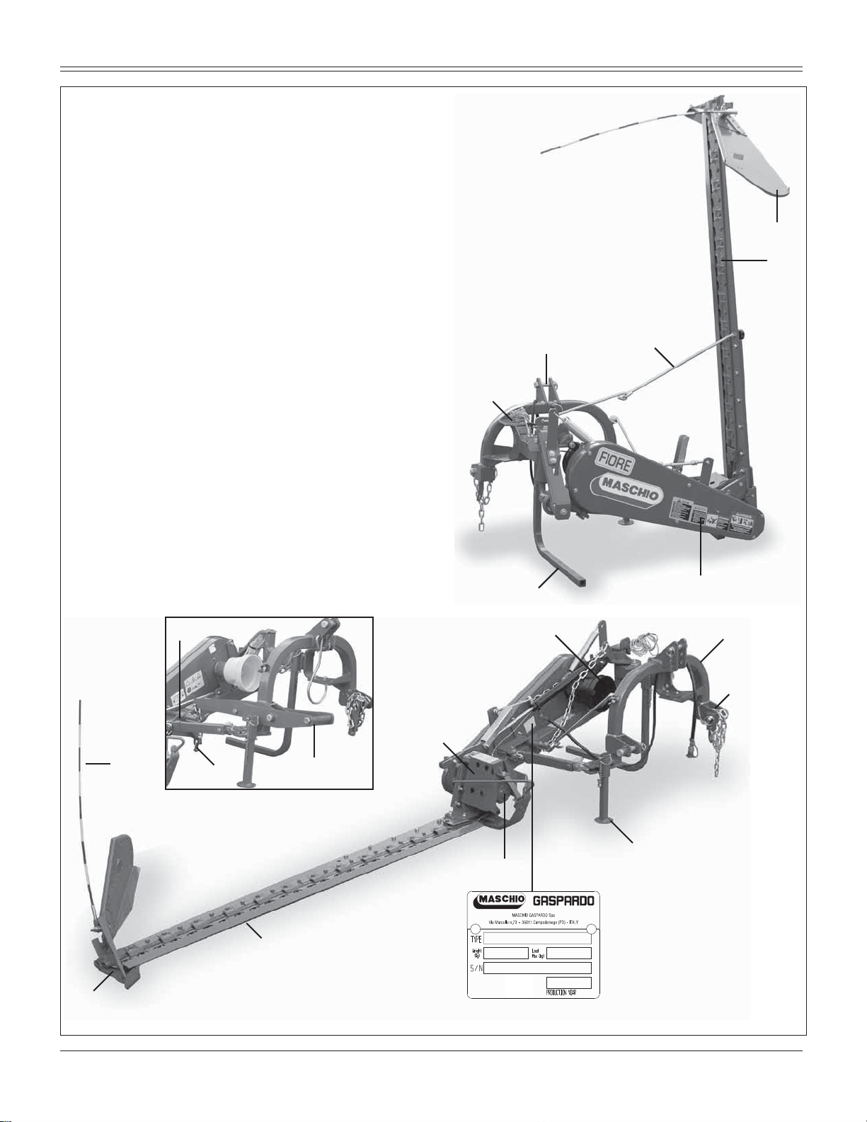
Description of the sickle bar mower.................5
Assembly drawing ............................................6
7HFKQLFDOVSHFL¿FDWLRQ
7HFKQLFDOVSHFL¿FDWLRQ......................................7
Handling ...........................................................7
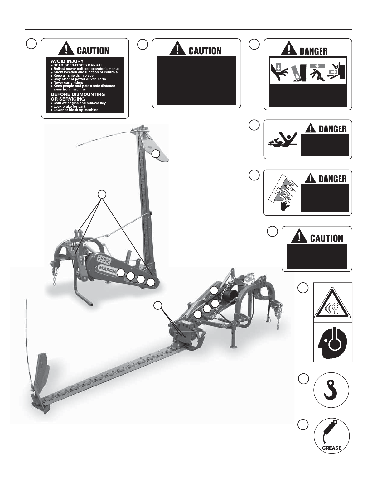
Safety lables
Safety-Alert lables ............................................8
,GHQWL¿FDWLRQPDFKLQH.......................................8
Machine safety labels.......................................8
Machine safety lables and position
Machine safety lables and position..................9
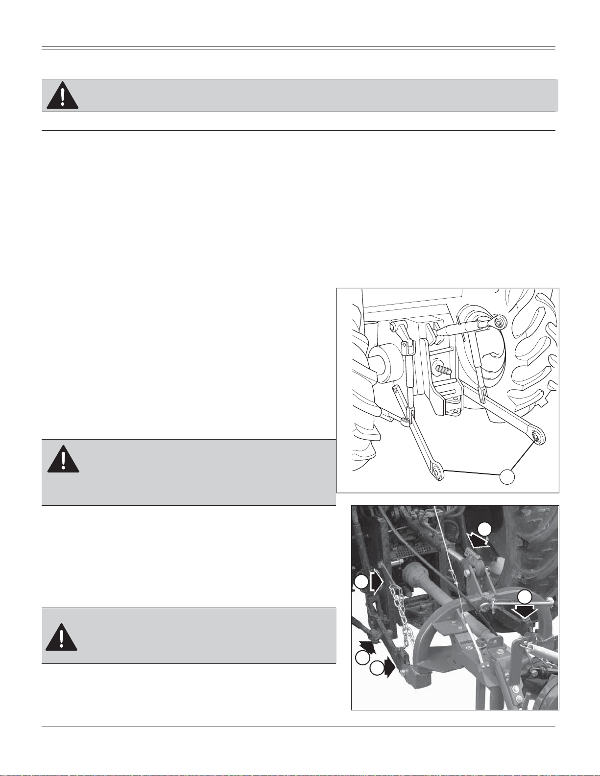
Preparing the tractor
Preparing the tractor.......................................10
Parking instruction..........................................10
Stay clear of rotating drivelines ......................10
Installing
Installing sickle bar mower on tractor ............10
PTO shaft adaptation......................................12
Stability of sickle bar and tractor during
transport .........................................................13
Parking instruction..........................................14
Stay clear of rotating drivelines ......................14
Removing
Removing sickle bar mower ...........................15
Operating
Operate safetly...............................................16
Wear appropriate clothing ..............................17
Stay clear of rotating drivelines .....................17
Operating - Mechanical Lifting System
Use of Mechanical lifting system ..................18
Adapting the sickle bar mower .......................18
Adjustment .....................................................18
Mowing...........................................................20
Operating - Hydraulic Lifting System
Use of Hydraulic lifting system ......................22
Adapting the sickle bar mower .......................24
Adjustment......................................................25
Using the lifting device....................................26
Operation of lifting device...............................26
0RZLQJRQÀDWJURXQG ....................................27
Mowing on slopes...........................................28
Operating - Quick Coupler
Quick Coupler.................................................29
Removing sickle bar mower with
Quick Coupler.................................................29