mason-lite.com
2
TABLE OF CONTENTS
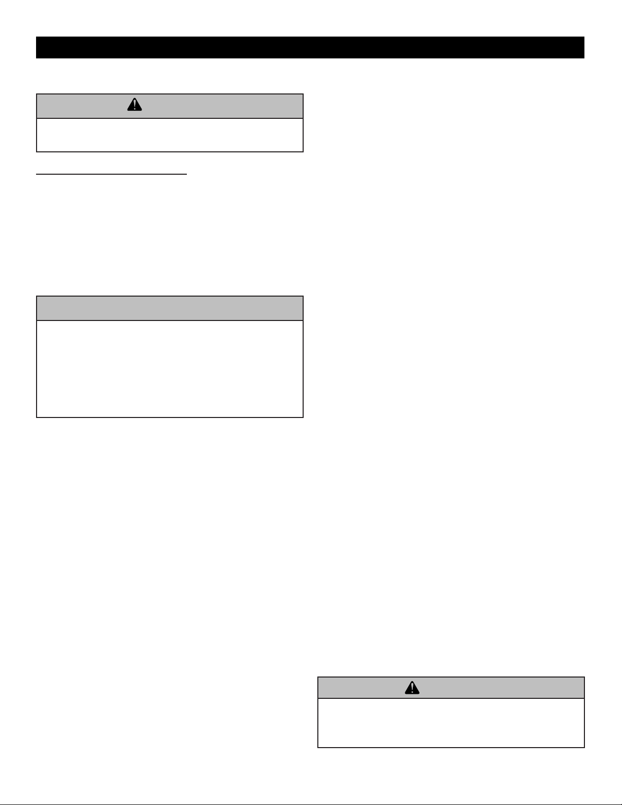
EXAMPLE LABEL.
Below is a sample picture of the rating plate that is located inside the lower dome side of your replace. Model Number, Date
of Manufacture and Serial Number should be stamped on the plate where indicated.
Cover Page..........................................................................................................1
Table of contents................................................................................................2
Example Rating Label......................................................................................2
Fireplace Parts Diagram ....................................................................................3
Customer Service & Replacement Parts..........................................................3
General Information ........................................................................................... 4
Introduction .....................................................................................................4
Before Beginning the Installation .....................................................................4
Statement of Intended Use ..............................................................................4
Product Overview.............................................................................................4
Firebox Dimensions ......................................................................................... 4
Safety Information.........................................................................................5 - 6
Carbon Monoxide Poisoning............................................................................5
General Safety Concerns.................................................................................5
Installing Television (TV) Above Fireplace .......................................................6
Location...............................................................................................................7
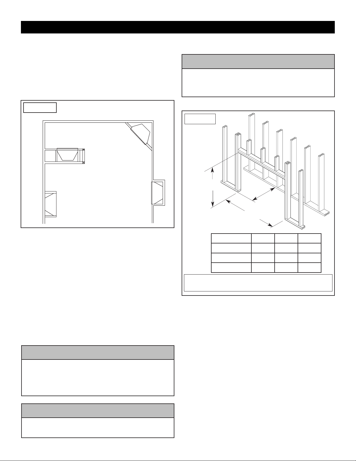
Typical Installations..........................................................................................7
Framing Dimensions ........................................................................................ 7
Seismic & Non-Seismic Code ..........................................................................7
Supporting Floor System...................................................................................8
Floor Framing...................................................................................................8
Rebar Locations...............................................................................................8
Wood Floor .........................................................................................................8
Crawl Space or Upper Floor.............................................................................8
Weight Determination ........................................................................................9
Other Weight Considerations...........................................................................9
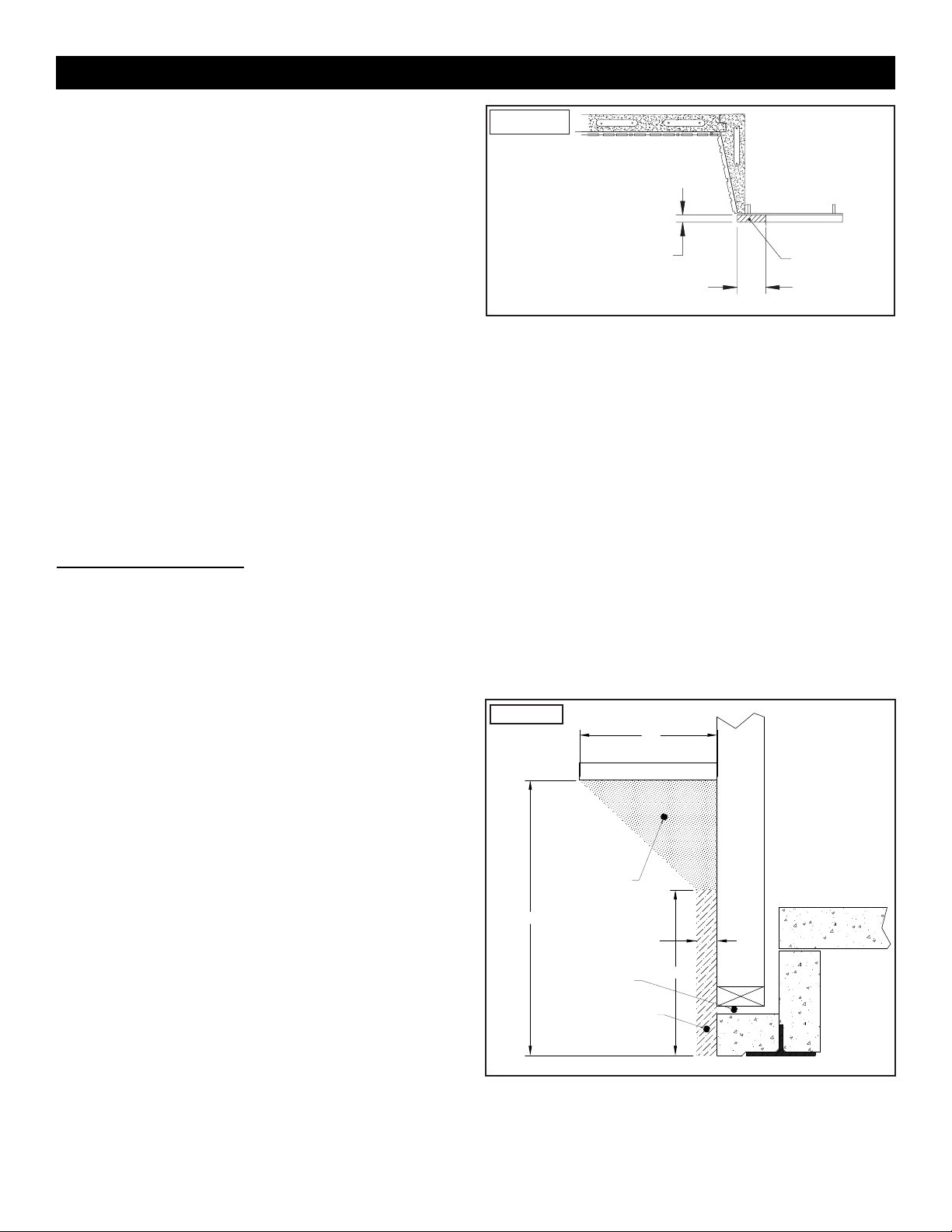
Clearances .................................................................................................10 - 11
The Importance of Clearances.......................................................................10
Clearances to combustibles...........................................................................10
Clearances to Combustible trim.....................................................................10
Interior Wall Materials..................................................................................... 11
Trim Facings.................................................................................................................... 11
Adjoining Room Walls .................................................................................... 11
Air for Combustion & Ventilation............................................................. 11 - 12
Providing Adequate Ventilation ...................................................................... 11
Unusually Tight Construction ......................................................................... 11
Unconned Space..........................................................................................12
Determining Total Air Volume .........................................................................12
Important Pre-Installation Information ...........................................................13
Overview..............................................................................................................13
Additional Materials Required ........................................................................13
Leveling and Aligning Components................................................................13
Field Assembly Procedures............................................................................13
Firebox Assembly Procedures.................................................................14 - 16
Raised and Flush Hearth Application..................................................................16
Other Installations.....................................................................................16 - 17
Gas Piping Installation.........................................................................................16
Electrical Line Feed.............................................................................................16
Firebrick Liner Installation ...................................................................................17
Modular Firebrick Liner........................................................................................17
Initial Fireplace Operation ...............................................................................17
Appendix I ........................................................................................................18
Appendix II .......................................................................................................19
Appendix III ......................................................................................................20
Limited Lifetime Warranty ...............................................................................23
Installer/Customer/Unit Information ............................................................... 24
FOR USE WITH LISTED ANSI Z21.11.2 UNVENTED DECORATIVE ROOM
HEATERS NOT TO EXCEED 40,000 BTU/HR (11.723W) CONSULT WITH
INSTRUCTIONS FOR THIS FIREBOX FOR FURTHER INFORMATION.
Refer to installation instructions and check local codes prior to installing. This appliance
must be installed in accordance with local codes if any, if not, in accordance with the
National Fuel Gas Code ANSI Z223.1 installation codes.
MFP586-NS_05/2022
ANSI Z21.91 Ventless Firebox Enclosures for Gas-Fired Unvented Decorated Room Heaters.
16” - 22” : MAX. PROJ.
22” & ABOVE: 10” MAX. PROJ.
0” - 10” : NO PROJECTIONS
10” - 16” : 1-1/2” MAX. PROJ.
DISTANCE FROM SIDE OPENINGS
3” MIN. : 1-3/4” MAX. PROJ.
MANTEL CLEARANCES
6391 Jurupa Ave., Riverside, CA 92504
THIS APPLIANCE NEEDS FRESH AIR FOR SAFE OPERATION
AND MUST BE INSTALLED SO THERE ARE PROVISIONS
FOR ADEQUATE COMBUSTION AND VENTILATION AIR.
DO NOT REMOVE THIS LABEL
SERIAL No.
LABC & LARC Compliant
MODEL No.:
MFP44VF MFP49VFMFP39VF
DATE OF MFG:
BOTTOM 0”
0”
42”
18-¹/2”
TOP/
BACK/
SIDES
OPENING
TO CEILING
CLEARANCES TO COMBUSTIBLES
RECESS
DEPTH
Tested & Listed By
Report No.
08-154
ICC Evaluation Services
Report No. 2401
EXAMPLE ONLY