masosine Certa Plus User manual

Certa Plus Pump User Manual
m-certa-plus-en-02 1
Contents
1 Declaration of conformity 3
2 Warranty 4
3 Intended use 4
4 How to handle stainless steel and other materials 5
5 Information for returning pumps 5
6 Environment and disposal of waste 5
7 When you unpack your pump 6
8 Sinusoidal pumps - an overview 6
9 Safety notes 6
9.1 Obligation of the operating organisation 7
9.2 Organisational measures 7
9.3 Obligation of the operators 7
9.4 Personnel training 7
9.5 Safety measures 7
9.6 Dangers when handling the machine 7
9.7 Safety measures in normal operation 7
9.8 Protective devices 7
9.9 Dangers due to hazardous pumped material 7
9.10 Dangers due to electrical energy 7
9.11 Dangers due to hydraulic energy 7
9.12 Special danger points 8
9.13 Constructional changes to the machine 8
9.14 Noise 8
9.15 Limit values for the pump 9
9.16 Maintenance and repair 9
9.17 Cleaning the pump 10
9.18 Faults 10
10 Pump specifications 11
10.1 Standards 11
10.2 Dimensions 12
Dimensions in millimetres: 12
Dimensions in inches: 12
10.3 Unit weights 12
11 Transport 13
12 Good pump installation practice 14
12.1 Dos and don'ts 14
12.2 Connection to the piping 15
12.3 Cavitation 16
12.4 Possible pump orientations 17
12.5 Connecting to a power supply 17
13 Start-up and operation 18
14 Flushing the seal system 19
14.1 Dynamic flushing 19
14.2 Static flushing device 20

14.3 Fitting a flush ring 20
15 Cleaning and sterilisation 21
16 Changing the oil 23
17 Heating and cooling option 24
18 Troubleshooting 25
18.1 Rework of front and back cover 25
18.2 Technical support 25
19 Disassembly and assembly 26
19.1 Disassembling the pump 26
19.2 Disassembling the mechanical seal system 29
19.3 Disassembling the middle housing 30
19.4 Disassembling the support / Changing the nozzle orientation 30
19.5 Assembling the support / Centering the rotor with the shim ring 31
19.6 Checking the X-Dimension 32
19.7 Assembling the front mechanical seal 32
19.8 Assembling the pump head 34
19.9 Assembling the flush ring of a single mechanical seal system 37
19.10 Assembling the back seal in a double mechanical seal system 37
20 Tightening torques 41
21 Parts lists 43
21.1 Rotor types 43
21.2 Pumps 44
21.3 Single mechanical seal 50
21.4 Flush ring 51
21.5 Atmospheric side of double mechanical seal 52
21.6 Static flush system 54
21.7 Dynamic flush system 55
21.8 Tools 56
22 Available wearing kits 57
23 Location of lot number on Certa Plus Parts 58
24 Trademarks 60
25 Disclaimers 60
26 Publication history 60
2 m-certa-plus-en-02

1 Declaration of conformity
Rev. 01/ 01.01.2021
EC/EU Declaration of Conformity (English translation)
for the purposes of Directive 2006/42/EC Annex II 1.A
1.
Manufacturer:
Watson Marlow GmbH, Steinbeisstr. 3, 74360 Ilsfeld (Germany),
Phone: +49(0)70629560-0
2.
3.
Name and address of the authorised documentation officer:
Watson Marlow GmbH, Steinbeisstr. 3, 74360 Ilsfeld (Germany)
Product : MasoSine Pump
Type designation : Certa, Certa Plus, SPS
4.
The above-mentioned manufacturer declares on his own responsibility that the product /
machine conforms to all regulations of this EC directive:
2006/42/EG
Directive 2006/42/EC of the European Parliament and of the
Council of 17 May 2006 on machinery and amending Directive
95/16/EC (recast) (1 ) Official Journal of the EU: L 157/24 of
09.06.2006
The above-mentioned manufacturer further declares that the product / machine is in conformity
with the following additional EC/EU directives or relevant regulations:
2014/30/EU
Directive 2014/30/EU of the European Parliament and of the
Council of 26 February 2014 on the harmonisation of the laws of
the Member States relating to electromagnetic compatibility
(recast), Official Journal of the EU: L 96/79 of 29.03.2014
Directive 2014/35/EU was complied with in accordance with Annex I No. 1.5.1 MRL
2006/42/EC with regard to its protection objectives.
According to Directive 2014/68/EU, Artikel 4.3 the above mentioned manufacturer certifies in
"accordance with the applicable good engineering practice" that the design and manufacture
ensures that the pump can be used safely according to the operating data on the nameplate
and in the instruction manual.
5.
The following harmonised standards - or parts thereof - have been applied:
EN ISO 12100: 2011-03
Safety of machinery - General principles for design - Risk
assessment and risk reduction
EN ISO 13857: 2008
Safety distances against reaching of hazardous areas
EN 809: 1998+A1:2009 +
AC:2010
Pumps and pump units for liquids - General safety requirements
The following other technical standards/specifications - or parts thereof - were applied:
DIN EN 10357:2014-03 Longitudinally welded stainless steel tubes for the food and chemical
industry
DIN 11851 Dairy pipe fittings
DIN 11864 Aseptic tube shipments
Ilsfled, 01.01.2021
Ort, Datum
Ewald Warmuth (Managing Director)
m-certa-plus-en-02 3

2 Warranty
Watson-Marlow GmbH MasoSine Division ("MasoSine") warrants this product to be free from defects in
materials and workmanship for a period of two (2) years from the date of shipment. This warranty
extends only to the original buyer. Products manufactured by others but furnished by seller are
exempted from this warranty and are limited to original manufacturer’s warranty.
This warranty shall not affect the warranty of the gear, motor or any other component which is not
manufactured by MasoSine.
MasoSine will not be liable for any loss, damage, or expense directly or indirectly related to or arising
out of the use of its products, including damage or injury caused to other products, machinery, buildings,
or property. MasoSine will not be liable for consequential damages, including, without limitation, lost
profits, loss of time, inconvenience, loss of product pumped, and loss of production. This warranty does
not obligate MasoSine to bear any costs of removal, installation, transportation, or other charges which
may arise in connection with a warranty claim.
Specific exceptions to the above warranty are:
Exceptions
Warranty and liability claims for personal and material damage are excluded if they are attributable to
one or several of the following causes:
oNormal wear and tear of the product
oAccident, misuse, or improper installation, operation, or maintenance of the product
oDeterioration of the products, in whole or in part, which is incidental to the transit of the product
oUse of the machine not as intended
oOperating the machine with defective safety devices or safety and protective devices not correctly
attached or not functioning
oNon-compliance with the operating instructions regarding transport, storage, installation, start-up,
operation, maintenance and setting of the machine.
oUnauthorised constructional changes to the machine
oAlterations or repairs performed by buyer without the written consent of MasoSine
oCatastrophe due to the effect of foreign bodies and acts of God
oAbnormal conditions such as, without limitation, corrosive attack or excessive dirt in the system, or
electrical supply failure
oWilful default or negligence by the buyer, its employees, agents consultants, or subcontractors
MasoSine grants no implicit warranties on the suitability of the products described for a certain
application. MasoSine accepts no liability for errors contained in this documentation or consequential
damage occurring due to the design, performance and the use of this documentation.
MasoSine’s “General sales and delivery conditions” contain full details. These are available to the
purchaser at the latest when the purchase contract is finalised.
Subject to the warranty provisions in this section, MasoSine warrants that if the buyer returns the
product within the twenty-four month warranty period and on MasoSine‘s examination such product
proves defective as to material or workmanship, MasoSine shall make good the defect without charge by,
at MasoSine‘s option:
lrepairing the defective product;
lreplacing defective components of the defective product; or
lreplacing the defective product in its entirety
In no event:
i. shall the cost of the customer's exclusive remedy exceed the purchase price of the product;
ii. shall MasoSine be liable for any special, indirect, incidental, consequential, or exemplary
damages, however arising, even if MasoSine has been advised of the possibility of such
damages.
MasoSine shall not be liable for any loss, damage, or expense directly or indirectly related to or arising
out of the use of its products, including damage or injury caused to other products, machinery, buildings,
or property. MasoSine shall not be liable for consequential damages, including, without limitation, lost
profits, loss of time, inconvenience, loss of product being pumped, and loss of production.
This warranty does not obligate MasoSine to bear any costs of removal, installation, transportation, or
other charges which may arise in connection with a warranty claim.
MasoSine shall not be responsible for shipping damage of returned items.
Notwithstanding any other terms of this section, MasoSine does not limit or exclude its liability for fraud
or fraudulent misrepresentation or for death or personal injury resulting from its negligence or the
negligence of its employees, agents or subcontractors.
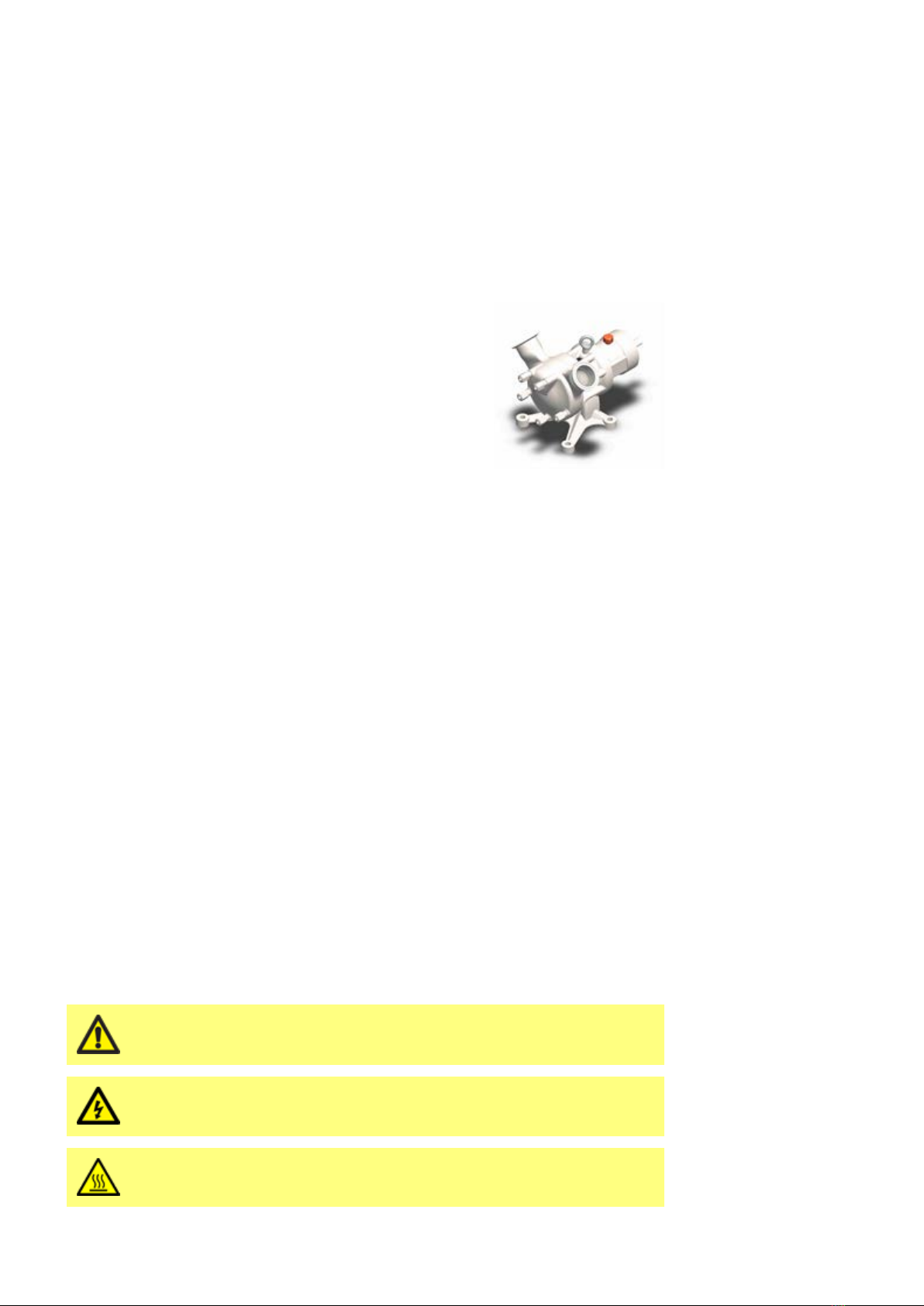
3 Intended use
The intended use of this product is listed in the order confirmation. The product should not be put to a
different use or a use going beyond the use described.
Consult MasoSine if you wish to change the product, its pressure, speed or operating temperature.
4 m-certa-plus-en-02

4 How to handle stainless steel and other materials
Stainless steel corrosion
Corrosion such as rust might be caused by chemical attack. Use only cleaning liquids which are suitable
for use with stainless steel. Take care when deciding on the concentration, temperature and exposure
time of the chemicals, to avoid chemical attack.
Non-galling material
A276/CF10SMnN or A494/CY5SnBiM (UNS# N26055) are the two optional rotor materials for MasoSine
Certa Plus series pumps. This non-galling alloy is a nickel based, corrosion resistant material which was
developed for use in positive displacement pumps. It is listed in the 3- A Standards and is thereby
accepted for use with product exposed surfaces. Do not use in combination with highly concentrated
nitric acid, for example, during passivation of new stainless steel piping systems. In this case remove the
rotor and the gate during the passivation process to avoid damage or chemical attack. When removing
the rotor, a double mechanical seal or a quench with a lip seal is needed, and you should close the
connections for the flushing fluid with plugs to keep the liquid in the pump during the passivation
process. Do not use a concentration of more than 3% of nitric acid for the CIP cleaning fluid.
Handling of elastomers and plastic parts after the passivation process
Check elastomeric and plastic parts after passivation for chemical attack and replace them if necessary.
5 Information for returning pumps
In compliance with the regulations in your area concerning the control of substances hazardous to health,
you are required to declare the substances which have been in contact with product (s) you return to
MasoSine or its distributors. Failure to do so will cause delays. Please ensure that you email us this
information and receive a RGA (Returned Goods Authorisation) before you despatch the product(s). A copy
of the RGA form must be attached to the outside of the packaging containing the product(s).
Please complete a separate decontamination certificate for each product and attach it to the outside of
the packaging containing the product (s). A copy of the appropriate decontamination certificate can be
downloaded from the Watson-Marlow Limited website at www.wmftg.com.
You are responsible for cleaning and decontaminating the product(s) before return.
6 Environment and disposal of waste
Always observe the local rules and regulations with respect to safe disposal of
waste.
Enquire within your local government about the possibilities for reuse or environment-friendly processing
of materials, (contaminated) lubricant and oil. Dispose of materials safely, and in accordance with
regulations in your area.
•Stainless steel parts should be recycled where possible
•Plastic should be recycled where possible
•Oil, grease and lubricants should be washed out and disposed of properly according to local
regulations
•Elastomers should be recycled where possible
m-certa-plus-en-02 5

7 When you unpack your pump
Unpack all parts carefully, retaining the packaging until you are sure all components are present and in
good order. Check against the components supplied list, below.
Packaging disposal
Dispose of packaging materials safely, and in accordance with regulations in your area. The outer carton
is made of corrugated cardboard and can be recycled.
Inspection
Check that all components are present. Inspect components for damage in transit. If anything is missing
or damaged, contact your distributor immediately.
Components supplied
lMasoSine Certa Plus series sinusoidal pump, bare shaft
lThe technical datasheet identifying, describing and defining the
pump
lOperating instructions
lBlocking tool and socket adapter
Optional items
lCoupling
lCoupling guard
lDrive
lFoot plate
Optional special design
lFlush systems
lGuard master
lJacketing for heating and cooling
Storage
This product has an extended shelf life. However, plastic parts and elastomeric parts should be stored in
a cool, dry environment. Care should be taken after storage to ensure that all parts function correctly.
8 Sinusoidal pumps - an overview
The functioning principle of MasoSine pumps is ingeniously simple.
The pump consists of modular components.
The sinusoidal rotor creates a chamber within the pump body four times per revolution, in which the
pumped fluid is displaced. As a filled chamber rotates, it contracts, closes and discharges its contents. At
the same time, the opposite chamber opens by the same fraction of a millimetre to draw in more fluid.
The result is a pump free of pulsation.
The gate works as a seal between the pressure side and the suction side of the pump. It prevents an
equalisation of the pressure created by the rotor, stopping it escaping to the suction side.
9 Safety notes
Knowledge of these safety instructions and of the safety regulations in your area is a requirement for
safe handling and trouble-free operation of this machine.
These operating instructions contain the most important instructions to operate the machine safely.
These operating instructions, especially the safety instructions, must be observed by all persons who
work on the machine. In addition, the rules and regulations for accident prevention applicable at the
place of use must be obeyed.
The following safety instructions must be observed absolutely. They are an essential and indispensable
part of the user documentation. Non-compliance can result in failure of warranty claims.
It is recommended in the interests of all involved to enter all installation measures, maintenance, fault
and repair cases, training courses, instructions and special occurrences in a logbook assigned to the
machine.
This symbol highlights a safety instruction which must be followed to avoid danger
to people or to the pump.
This symbol means: Beware of high voltage.
This symbol means: Caution, hot surface.
6 m-certa-plus-en-02

Caution: The pump contains rotating parts. The user must take care not to trap
fingers, loose clothing, etc. inside the pump.
9.1 Obligation of the operating organisation
The operating organisation must ensure that people who work on the machine are familiar with and
comply with the regulations concerning working safety and accident prevention.
9.2 Organisational measures
The personal protective equipment required must be provided by the operating organisation. Safety
devices must be checked regularly.
9.3 Obligation of the operators
People who work on the machine must observe the relevant safety regulations concerning working safety
and accident prevention before starting work; must read the safety chapter and the warning notes in
these operating instructions.
9.4 Personnel training
Only trained people may work on the machine. Their responsibilities must be defined clearly for
assembly, start-up, operation, setting, maintenance and repairing.
9.5 Safety measures
The operating instructions must be kept with the machine. General and local regulations for accident
prevention and environmental protection, and the operating instructions, must be observed. Safety and
danger warnings on the machine must be legible.
9.6 Dangers when handling the machine
The MasoSine pump is built according to state-of-the-art principles and the recognised safety engineering
rules. Nevertheless, danger to life and limb of the user or third persons, or impairments to the machine or
to other assets, can arise in its use.
The machine must be used only:
lfor its intended use
lif it is in a safe engineering condition.
Faults which may compromise safety must be rectified immediately.
9.7 Safety measures in normal operation
Operate the machine only if all protective devices are functioning. Before switching the machine on make
sure that no one can be endangered when the machine starts. At least once per shift inspect the machine
for damage and for proper functioning of the safety devices.
9.8 Protective devices
All protective devices must be attached correctly and functioning before every start- up. Protective
devices may be removed only after the machine has stopped and protection measures against restarting
the machine have been taken.
After spare parts have been fitted, protective devices must be attached according to the operating
organisation’s regulations.
If contact with hot or cold machine parts could be dangerous, protection must be provided for the pump
user.
9.9 Dangers due to hazardous pumped material
If hazardous material is to be pumped, the appropriate regulations must be observed.
9.10 Dangers due to electrical energy
Work on the electrical supply must be performed only by an electrician.
Check the electrical equipment of the machine regularly. Rectify loose connections
and scorched cables immediately.
Keep the control cabinet locked closed or secured with a tool. Access is allowed only to authorised
personnel.
If work on parts conducting voltage must be done, call in a second person to switch off the mains power if
necessary.
Electrical connection of the pump must be made according to local regulations, by skilled personnel only.
9.11 Dangers due to hydraulic energy
Only personnel with special knowledge and experience in hydraulics may work on hydraulic devices.
Relieve the pressure in the system sections and pressure lines to be opened before starting repair work.
Replace hydraulic hose lines at appropriate intervals, even if no safety-relevant defects are detectable.
m-certa-plus-en-02 7

9.12 Special danger points
The pump contains a rotating rotor, which can crush or
sever fingers and hands. The pump must be guarded so
that it is not possible for people to hold the pump by its
inlet or delivery ports with the rotor running. When the
rotor is stationary, the drive must be secured against
unintentional start-up. Increased danger exists if pipes are
dismantled or the pump is open.
9.13 Constructional changes to the machine
Make no changes, attachments or conversions to the machine without the manufacturer’s approval. All
conversion measures require the written confirmation of Watson-Marlow GmbH MasoSine Division.
Replace machine parts which are not in perfect condition immediately. Use only original spare and
wearing parts. Parts that are not obtained from MasoSine are not guaranteed to be designed and
manufactured in compliance with load and safety requirements.
The warranty is invalid if genuine spare parts from MasoSine are not used.
9.14 Noise
The continuous sound pressure level proceeding from the machine should not exceed 70 dB(A). Higher
sound pressure levels that can cause deafness can arise, depending upon local conditions. If this occurs,
protect the operating personnel with appropriate protective equipment / protective measures.
8 m-certa-plus-en-02

9.15 Limit values for the pump
The pump’s maximum speed, maximum pressure and maximum temperature are included in the technical
data sheet supplied with each pump. These limit values must not be exceeded in any circumstances. This
applies in particular when using a frequency converter.
If pump is supplied without a drive, the following values apply:
P100 P200 P250 P300 P400
Maximum pressure* 6 bar/
87 psi
6 bar/
87 psi
6 bar/
87 psi
6 bar/
87 psi
6 bar/
87 psi
Maximum speed* 1000rpm 1000rpm 800rpm 600rpm 600rpm
Maximum temperature* 100C/
212F
100C/
212F
100C/
212F
100C/
212F
100C/
212F
Minimum temperature* -20C/-4F -20C/-4F -20C/-4F -20C/-4F -20C/-4F
* These limits may vary, depending on the drive, the application and the rating of the pump. (See your
purchase order confirmation, or contact MasoSine and quote your pump’s serial number.) On customer
request, higher pressures and temperatures are possible.
9.16 Maintenance and repair
Maintenance and repair work on the pump should only be carried out by trained service personnel, who
should have read and understood this manual prior to installing, operating or servicing this equipment.
Inform operating personnel before starting maintenance and repair work. Protect all plant parts and
operating media connected before and after the machine, such as compressed air and hydraulics, against
unintentional start-up. In all maintenance, inspection and repair work, switch the machine off and secure
the main switch against unintentional start-up.
Secure larger assemblies carefully to lifting gear. Check loosened screw connections for firm seating. Use
only original spare parts.
After maintenance work is finished, check the safety devices are functioning.
Bearings maintenance
Note: Remove the bearing housing only to replace or adjust the shim ring. Do not attempt to
dismantle the power end of the pump or replace the bearings. Pumps needing repair, servicing,
new bearings or other work on the power end must be returned to MasoSine for attention. Special
training is available. Please contact MasoSine for further information.
Certa Plus P100/P200/P250/P300/P400 bearing replacement intervals:
The table below shows the recommended intervals in hours, for renewing the bearings subject to the
maximum speed and pressure, as listed in the table See Limit values for the pump above
Certa Plus pump model Bearings maintenance interval
P100 10,000 hrs
P200 10,000 hrs
P250 10,000 hrs
P300 10,000 hrs
P400 10,000 hrs
m-certa-plus-en-02 9

Maintenance intervals and actions
Interval Sub-assembly
(if present)
Skill
level
Action
According to manufacturer's
specifications
Coupling Operator Check coupling for wear
Weekly Bearing frame Operator
Expert
Check oil level
Check for strange sounds
Refill/change lubricant oil if
necessary
Mechanical seal Operator
Expert
Check for leaks
In case of leakage:
- Determine the degree of leakage
- Consult Watson-Marlow MasoSine
- Replace the wearing parts
Elastomeric seals
(e.g. pump housing)
Operator
Expert
Check for leaks
In case of leakage:
- Determine the degree of leakage
- Consult Watson-Marlow MasoSine
- Replace the O-rings
Heating Expert Check the electrical connection
Check the function
Motor Expert Check for wear
Check for leakage
Check for strange sounds
Every 6 months or 500
cleaning cycles
Mechanical seal and
Elastomers
Expert Check for leakage
Check for chemical attack
Check for wear
Check elastomer parts for elasticity
and changes in characteristics
Replace if necessary
Annually Bearing frame Expert Change lubricant oil
For continuous operating: see
'Bearings maintenance'
Bearing frame Expert Change bearings
Contact Watson-Marlow MasoSine
for assistance
Points to observe during maintenance:
lClean all accessible seal grooves before assembling
lAll accessible surfaces, threads and dismantled components shall be cleaned with a suitable cleaning
agent
lClean the thread in the shaft and on the locking nut before installing the lock nut again, to prevent
the build-up of microorganisms in the area of the thread (for example, use a small brush and / or
compressed air or pressurised water / cleaning fluid for the blind hole)
lCheck elastomer parts for elasticity and changes in characteristics (e.g. stickiness, roughness,
discolouring, substantial deformation)
lTo assemble elastomer parts in food and beverage applications, use only NSF H1 listed lubricants that
are compatible with the elastomer material. Use as little lubricant as possible.
9.17 Cleaning the pump
Handle substances and materials used correctly, especially when working on lubricating systems and
when cleaning with solvents. For information on cleaning the parts in contact with the pumped fluid, see
"Cleaning and sterilisation" on page21.
9.18 Faults
If an operating fault occurs, switch off the machine and secure it against unintentional start-up.
10 m-certa-plus-en-02

10 Pump specifications
Your pump carries a name plate on the bearing housing. It includes a serial number, which identifies the
features of the product. The serial number also appears on the technical datasheet.
An example name plate is shown below.
(the abbreviations on the label are as follows: Pm=maximum pressure, max.=maximum speed, s/n=serial number)
10.1 Standards
Standards applicable to the pump connected
to a drive:
See "Declaration of conformity" on page3 or
supplied with the pump.
m-certa-plus-en-02 11

10.2 Dimensions
Dimensions in millimetres:
Model
Nozzles Foot
N1 N2 N3 F1 F2 F3 F4 F5 L1 L2 H1 H2 C1 C2 C3
P100 139 85 10 120 135 Ø12 143 57 265 50 95 129 Ø28 8 31
P200 155 99.5 10 120 135 Ø12 167.5 81.5 298.5 50 109.5 145 Ø28 8 31
P250 191.5 138.5 11.5 190 175 Ø17 219 84 352 50 150 180 Ø28 8 31
P300 237.5 152.5 17.5 250 215 Ø20 285 154 455.5 80 170 220 Ø50 14 53.5
P400 323.5 169 31 266.5 254 Ø21 301 169 513.5 77 200 292.5 Ø50 14 53.5
Dimensions in inches:
Model
Nozzles Foot
N1 N2 N3 F1 F2 F3 F4 F5 L1 L2 H1 H2 C1 C2 C3
P100 5.47 3.35 0.39 4.72 5.31 Ø0.47 5.63 2.24 10.43 1.97 3.74 5.08 Ø1.10 0.31 1.22
P200 6.10 3.92 0.39 4.72 5.31 Ø0.47 6.59 3.21 11.75 1.97 4.31 5.71 Ø1.10 0.31 1.22
P250 7.54 5.45 0.45 7.48 6.89 Ø0.67 8.62 3.31 13.86 1.97 5.91 7.08 Ø1.10 0.31 1.22
P300 9.35 6.00 0.68 9.84 8.46 Ø0.79 11.22 6.06 17.93 3.15 6.69 8.66 Ø1.97 0.55 2.11
P400 12.74 6.65 1.22 10.49 10.00 Ø0.83 11.85 6.65 20.22 3.03 7.87 11.52 Ø1.97 0.55 2.11
10.3 Unit weights
Pump model Pump only Standard baseplate
P100 16kg (35lb 4oz) Part No. KK-... 11kg (24lb 4oz)
P200 21kg (46lb 5oz) Part No. KK-... 11kg (24lb 4oz)
P250 40kg (88lb 3oz) Part No. KR-... 15kg (33lb 7oz)
P300 67kg (147lb 11oz) Part No. KM-... 19kg (41lb 14oz)
P400 115kg (253lb 9oz) Part No. KG-... 31kg (68lb 5oz)
12 m-certa-plus-en-02

11 Transport
Choose the right means of transport according to the size of the pump and the drive. The pump must be
suspended correctly for transport. If using a crane or fork-lift truck, the ropes or belts must be sufficiently
dimensioned. If the pump is transported with a lift truck or fork-lift truck, note that the unit's centre point
is not necessarily the centre of gravity.
m-certa-plus-en-02 13

12 Good pump installation practice
The motor shaft and pump shaft connection must be guarded to protect the user
from contact, when in use.
lPlace the pump on a level surface
lDo not start the pump without a coupling guard to protect the user from contact.
lThe mounting surface should be strong enough to support the pump.
lThere should be sufficient space for maintenance work around the pump.
lThe motor must receive an adequate air supply.
lThe unit must be protected against static charge.
lEnsure the front housing is accessible for easy maintenance.
lAlign the pump shaft with the drive shaft.
;
12.1 Dos and don'ts
lDo not build a pump into a tight location without adequate airflow around the pump.
lDo not pump any chemical not compatible with the materials of the pumphead.
lDo keep delivery and suction pipes as short and direct as possible - though ideally not shorter than
one metre - and follow the straightest route. Use bends of large radius: at least four times the pipe
diameter. Ensure that connecting pipework and fittings are suitably rated to handle the predicted
pipeline pressure. Avoid pipe reducers and lengths of smaller bore pipe than the pumphead section,
particularly in pipelines on the suction side. Any valves in the pipeline must not restrict the flow. Any
valves in the flow line must be open when the pump is running.
lDo use suction and delivery pipes equal to or larger than the nozzle diameter bore.
lDo site the pump at or just below the level of the fluid to be pumped if possible. This will ensure
flooded suction and maximum pumping efficiency.
lValves in the process flow must be opened before the pump operates. Users are advised to fit a
pressure relief device between the pump and any valve on the discharge side of the pump to protect
against damage caused by accidental operation with the discharge valve closed.
14 m-certa-plus-en-02

12.2 Connection to the piping
Before connection, clean the piping and remove foreign bodies such as welding
residues.
Avoid forces and torques acting from the piping on the pump connections (e.g.
distortion, expansion due to temperatures etc.) by using compensators or other
suitable equipment.
The user must ensure that a pressure rise above the pressure agreed in the
purchase order and listed in the technical data sheet is not possible.
MasoSine pumps normally run with such a low resonant frequency that no damage
results. However, particularly when running with inverters, certain frequencies can
cause interference vibrations which must be avoided. It is important during
commissioning to ascertain whether such vibrations exist and to define them, so
that the inverter can be programmed to avoid these frequencies. Similarly,
interference from cavitation or rigid lines must be avoided.
m-certa-plus-en-02 15

12.3 Cavitation
Cavitation is a problem in certain devices where fluid interacts with a moving surface. It can occasionally
occur in sinusoidal pumps.
Where a surface moves through a fluid, low pressure areas are formed on the surface. The faster the
surface moves, the lower the pressure around it can become. If the static pressure of the liquid falls
below its vapour pressure, vapour bubbles form on the pressure side. These implode, causing very high,
short-term pressure peaks up to several thousand bar. These pressure peaks can cause material erosion
and are noisy.
To identify cavitation
If the pump is very noisy and vibrates vigorously, along with the pipe system attached to the pump,
cavitation is likely to be the cause.
To avoid or remove cavitation
Increasing the inlet pressure on the suction side, installing a larger diameter or shorter inlet pipe or
slowing the pump may solve the problem. Make sure that the pump is not starved of duty fluid at all
times.
lTo prevent cavitation, always ensure that NPSHA> NPSHR.
Cavitation can destroy the pump. The operator must ensure that the pump can
work free of cavitation.
16 m-certa-plus-en-02

12.4 Possible pump orientations
The pump can be positioned in one of eight orientations, and can rotate clockwise or counter-clockwise.
10-02 12-03 02-04 * 03-06
04-08 06-09 08-10 * 09-12
Unless you specify otherwise when ordering, the pump is delivered in position 10-02.
Special customised nozzle orientations are possible.
*Please note: According to EHEDG regulations, the pump head should always be completely self-draining.
In a standard installation this can only be assured in the 02-04 or 08-10 nozzle position.
Changing the pump orientation
See "Disassembling the support / Changing the nozzle orientation" on page30 for details about changing
the pump orientation.
12.5 Connecting to a power supply
The motor must be connected according to local regulations by a qualified person.
See the instruction manual supplied with your drive motor.
m-certa-plus-en-02 17

13 Start-up and operation
lIf you are starting the pump for the first time, or have performed cleaning or
repair work, check first that all screws are correctly and completely
tightened.
lThe pump may have been contaminated during transport. Remove the pump
front cover and clean if necessary before start-up.
Observe the appropriate regulations if hazardous fluid is to be pumped.
Ensure that the pump is installed in an appropriate position with all necessary
safety guards and precautions (sensors, switches, pressure gauges, etc.).
MasoSine pumps must be primed before use. Before commissioning and during operation, the pump must
be filled with fluid, with the fluid level above the rotor (see diagram). This can be done manually through
a side channel of your system’s pipework, or by using a vacuum device where very viscous fluids are to
be pumped; contact MasoSine for further information. The need to prime can be avoided by leaving
product in the pump after it is stopped; by leaving CIP or SIP fluid in the pump after cleaning.
Before start-up, make sure that all valves on the pressure and suction sides are
open. The pump must not pump against a closed valve without an over-pressure
valve.
If the pump leaks, stop pumping as quickly as possible and replace the damaged
sealing elements. See "Disassembling the mechanical seal system" on page29.
The operator must ensure that the pump can work free of cavitation. Cavitation can
destroy the pump. See "Cavitation" on page16.
18 m-certa-plus-en-02

14 Flushing the seal system
In order to prevent a dry run and to ensure a proper working sealing system a seal
flush is recommended.
Flushing fluid at atmospheric pressure—usually water—flushes the area behind the seal system and
prevents the product from hardening and damaging the seal system. If a static flushing device is fitted,
the flushing fluid fills the area behind the seal.
lThe flushing medium must be at least suitable to the product being pumped. It should not contain
abrasive particles, which would damage the seals. We recommend that transparent plastic tubes are
used as flushing tubes.
lIt can also be used to create a (bacteria tight) barrier to the atmosphere.
lThe single mechanical seal should be flushed without pressure: the flushing fluid should be allowed to
drain from the system without pressure. The double mechanical seal can be used pressureless or
alternatively with an overpressure.
lFill the pump with liquid to prevent it from running dry, possibly via a separate intake valve
connected to the suction or pressure pipe.
lIf your pump is set up for permanent flushing, always check the intake and outlet (see diagram
below).
INTAKE OUTLET
14.1 Dynamic flushing
The picture shows a tube connected for the flush system. The tubing should have an outer diameter of
8mm or connection with G1/8 thread.
The picture shows tubes installed for flushing.
You should connect the tubes to the highest possible point (outlet) and the lowest possible point
(intake), so that there is a 180° angle between them.
m-certa-plus-en-02 19

Plug all other possible connections on the frame, using the
threaded plugs supplied with the pump (see "Parts lists" on
page43 for the part numbers). The other connections are
intended for use with different orientations of the pump's
nozzles (see "Possible pump orientations" on page17).
14.2 Static flushing device
Before commissioning, fill the flushing device (if supplied) with a suitable flushing fluid, depending on the
product being pumped. Fill the sight glass with flushing fluid until the fluid level is just below the bend in
the outlet pipe.
Fitting the static flushing device
The static flushing device can be fitted to a Certa Plus pump with a flush ring or a double mechanical
seal. See also "Assembling the pump head" on page34.
The connection with the vent pipe must be connected to the highest flush port.
lFor a 10/2 nozzle orientation this is the flush port located 45° off the vertical axis.
lFor all other nozzle orientations this is the flush port on top of the pump.
The connection with the sight glass must be fitted to the flush port which is offset by 45° from the
vertical axis.
Remove the threaded plug of the required flush port by using a 10mm Socket with extension.
Apply an appropriate sealing material (e.g. Teflon tape) to both threads of the double nipples and fit
them to the flush ports using a 14mm spanner.
Connect the sight glass and the vent pipe with the installed connectors using two 14mm spanners to
tighten them.
Check if the reservoir and the vent pipe are at the same height and close all flush ports.
Removing the static flushing device
The static flushing device must be emptied and removed before disassembling the pump. To do this,
open the flush port at the lowest point of the pump.
After the flushing device has been emptied, reverse the sequence of operations described above to
remove it.
14.3 Fitting a flush ring
See "Assembling the flush ring of a single mechanical seal system" on page37.
20 m-certa-plus-en-02
This manual suits for next models
5
Table of contents
Other masosine Water Pump manuals
Popular Water Pump manuals by other brands

Dakota Digital
Dakota Digital Odyssey ODYR-25-1 manual

BVA
BVA P1201 instruction manual

Tri-Clover
Tri-Clover Tri-Flo CL Series Service & installation manual

Liberty Pumps
Liberty Pumps 441 installation manual

Aquadistri
Aquadistri SuperFish Volcano user manual

LEYBOLD
LEYBOLD TURBOVAC 340 M operating instructions

Oase
Oase AquaMax Eco Expert 6800 operating instructions

Eaton
Eaton 74318 Repair Information

Wilo
Wilo Padus UNI Installation and operating instructions

DIVERSITECH
DIVERSITECH Asurity ULTRACP-22 installation instructions

DROPSA
DROPSA 31070 Series User Operating and Maintenance Manual

Ingersoll-Rand
Ingersoll-Rand P237A1-EU Maintenance information