Revision 8.0 / July 2015
4.5 Obligation of the personnel
All persons who are authorized to work on the machine obligate themselves to observe the basic regulations concerning working safety
and accident prevention before starting work, to read the safety chapter and the warning notes in these operating instructions and to
confirm by their signature that they have understood these.
4.6 Training of the personnel
Only trained and instructed personnel may work on the machine. The responsibilities of the personnel shall be defined clearly for
assembly, start-up, operation, setting, maintaining and repairing.
Personnel under training may work on the machine only under supervision of an experienced person.
4.7 Informal safety measures
The operating instructions must be kept constantly at the place of use of the machine. The generally valid as well as the local
regulations for accident prevention and environmental protection shall be provided and observed in addition to the operating
instructions. All safety and danger warnings on the machine shall be kept in legible condition.
4.8 Dangers when handling the machine
The WATSON-MARLOW MasoSine-PUMPS is built according to the state of the art and the recognized safety engineering rules.
Nevertheless danger to life and limb of the user or third persons or impairments to the machine or to other assets can arise in its use.
The machine must be used only:
for the intended use (see technical datasheet)
in perfect safety engineering condition.
Faults which can impair safety must be rectified immediately.
4.9 Safety measures in normal operation
Operate the machine only if all protective devices are fully functioning. Before switching the machine on make sure that no one can be
endangered by the starting machine. At least once per shift inspect the machine for “externally detectable damage” and for functioning
of the safety devices.
4.10 Protective devices
All protective devices must be attached correctly and functioning before every start-up.
Protective devices may be removed only
- after standstill and simultaneous protection against restarting the machine.
On delivery of part components the protective devices must be attached according to regulations by the operator.
If hot or cold machine parts can lead to danger, these must be protected by the operator on site against contact.
4.11 Dangers due to hazardous pumped material
In the case of hazardous pumped material (according to ArbStoffV) the corresponding regulations must be complied with.
4.12 Dangers due to electrical energy
Have work on the electrical supply performed only by an electrician. Check the electrical equipment of the machine
regularly. Rectify loose connections and scorched cables immediately.
Keep the control cabinet closed always. Access is allowed only to authorized personnel with key or tool.
If work on parts conducting voltage is necessary, call in a second person who switches off the main switch if
necessary.
If you make the electrical connection of the pump, act according to DIN EN 60204!
Connect only by skilled personnel!
4.13 Dangers due to hydraulic energy
Only personnel with special knowledge and experience in hydraulics may work on hydraulic devices.
Relieve the pressure in system sections and pressure lines to be opened before starting repair work. Replace hydraulic hose lines at
appropriate intervals, even if no safety-relevant defects are detectable.
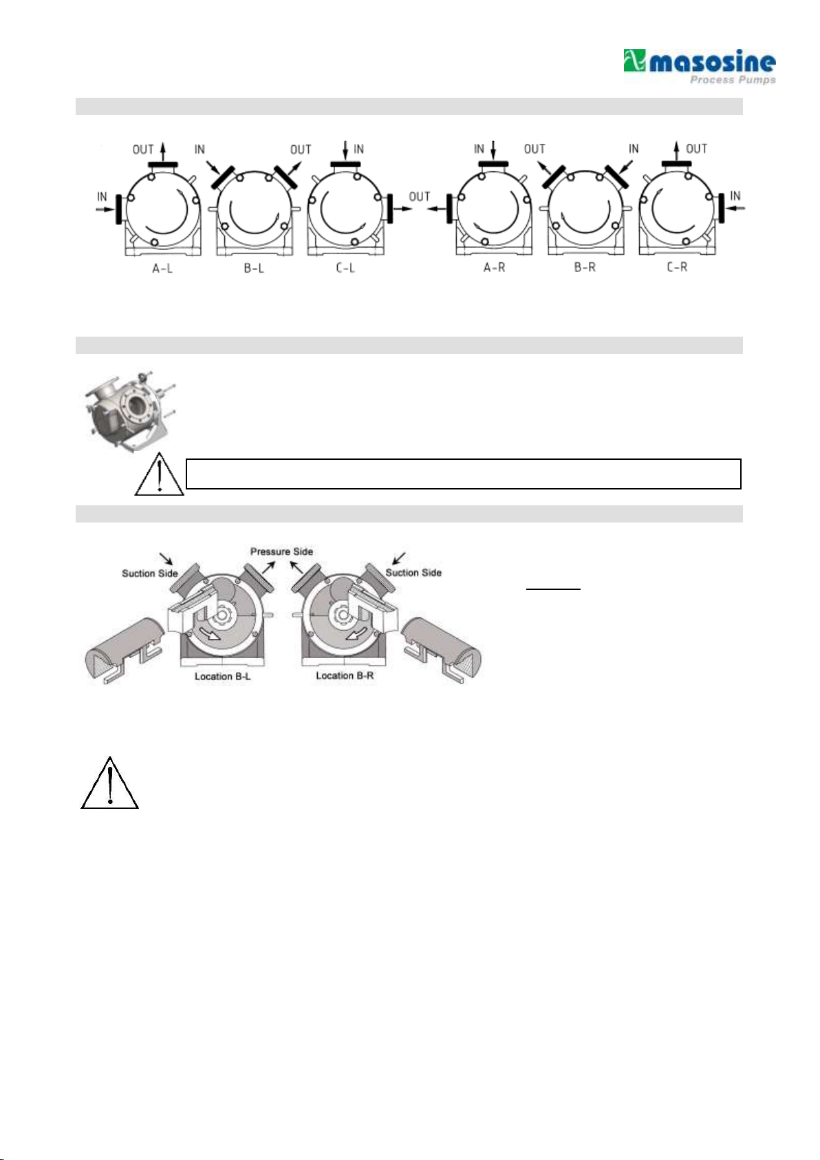
4.14 Special danger points
Rotating rotor in the pump. Danger of crushing or cutting off fingers and hands. The
pump must be protected by the customer so that it is not possible for persons to grasp in
the opening with the rotor running. In the case of work on the stationary Rotor, the drive
must be secured against unintentional switching on. Increased danger exists with
dismantled pipes and opened pump.