Massoth PluG Interface User manual

PluG Schnittstelle
PluG Interface

2
WICHTIGER HINWEIS
Sehr geehrte Kunden, wir empfehlen diese
Produktdokumentation und vor allem auch
die Warnhinweise vor der Inbetriebnahme
gründlich zu lesen und diese zu Beachten.
Für Schäden durch Nichtbeachtung der Hin-
weise übernimmt Massoth keine Haftung.
IMPORTANT NOTE
Dear customer, we strongly recommend
that you read this manual and the warning
notes thoroughly before installation and
operation. Massoth is not responsible for
any damage if this manual or the warning
notes are disregarded.
Inhaltsverzeichnis
• Information...........................................
• Beschreibung (Funktionsumfang).........
• Lieferumfang.........................................
• Warnhinweise.......................................
• Einbau und Anschluss..........................
• Einbauhinweise.....................................
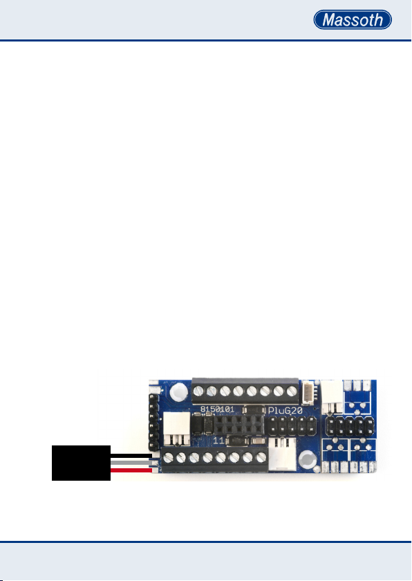
• Bild: PluG Schnittstellenplatine mit
Kontaktbelegung...................................
• Anschluss (Grundfunktion)...................
• Erweiterter Anschluss...........................
• Hilfsspannung.......................................
• Lautstärkeregler....................................
• Reedkontakte........................................
• Taktgeber..............................................
• Pufferspeicher (PowerCap)...................
• BUS......................................................
• Servobetrieb..........................................
• Entkuppleranschluss.............................
• Inbetriebnahme.....................................
• Programmierung...................................
• Technische Daten..................................
• Garantie & Kundendienst......................
• Kontakt zum Hersteller..........................
• Bild: PluG Schnittstellenbelegung ge-
mäß RailCommunity Norm RCN-123....
Table of Contents
• Information...........................................
• Description............................................
• Scope of Supply....................................
• Warning Notes......................................
• Installation and Connection..................
• Installation Notes..................................
• Illustration: PluG Interface
with pinning details...............................
• Connection (basic functions)................
• Connection (extended)..........................
• Auxiliary Voltage...................................
• Volume Control.....................................
• Reed Contacts.......................................
• Hall Sensor (Clock)...............................
• Buffer Operation (PowerCap)................
• BUS......................................................
• Servo Operation....................................
• Uncoupler Operation.............................
• Getting started......................................
• Programming........................................
• TechnicalSpecications.......................
• Warranty & Customer Service..............
• Contact the Manufacturer.....................
• Illustration: PluG Interface Pinning acc.
to RailCommunity standard RCN-123...
3
3
3
3
4
4
5
6
7
7
8
8
9
9
10
10
10
11
11
12
12
13
15

3
1. Information
1.1 Beschreibung (Funktionsumfang)
Die PluG Schnittstellenplatine ist
die universelle Basis für den Deco-
der und das Soundmodul. Durch
die standardisierte Schnittstellen-
technik lassen sich Komponenten
problemlos tauschen, ohne die
VerkabelungderLokzumodi-
zieren.
1.2 Lieferumfang
•eMOTION PluG Schnittstelle
•Bedienungsanleitung
1.3 Warnhinweise
•Beachten Sie unbedingt die Do-
kumentation Ihres Decoders bzgl.
der eingestellten Spannung der
Funktionsausgänge. Vergewissern
Sie sich vor dem Anschluss der
Lampen und Funktionsausgänge
das die Spannung entsprechend
der CV-Liste richtig eingestellt ist!
•Funktionsausgänge dürfen
niemals mit einer Fremdspannung
verbunden werden, dies führt zur
Beschädigung, im schlimmsten
Fall zur Zerstörung des Decoders.
Prüfen Sie vor Anschluss die
Polarität der Decoderausgänge.
Verstärkte Ausgänge sind immer
(-), unverstärkte Ausgänge sind
immer (+).
1. Information
1.1 Description
The PluG interface board is the
universal base for decoders and
sound modules. This standard
interface allows quick and easy re-
trotinstallationandmaintenance
without touching the locomotives
wiring.
1.2 Scope of Supply
•eMOTION PluG Interface
•manual
1.3 Warning Notes
•Please refer to the decoders docu-
menation concerning the settings
of the function outputs. Make sure
the CVs of the function outputs are
set to the appropriate value before
hooking up any lights or other
accessories.
•function outputs must not be
connected with a foreign power
source, this results in damage or
total loss of the decoder. Please
check the polarity of the function
outputs before connecting. Rein-
forced outputs are always (-), not
reinforced outputs are always (+).

4
2. Einbau und Anschluss
2.1 Einbauhinweise
•Vor dem Einbau der Schnittstelle
muss sämtliche Elektronik aus der
betreffenden Lok entfernt werden.
Dies kann unter Umständen auch
Lampenplatinen mit einer analogen
Schaltlogik betreffen.
•Bauen Sie die Schnittstelle ein,
ohne weitere Komponenten
(Decoder, Soundmodul) ein. Diese
werden anschließend aufgesteckt.
•Die Funktionsausgänge FA1...FA4
sowie LV und LH sind gemäß PluG
Norm immer verstärkte Ausgänge
(OpenCollector), die Polarität ist
immer (-). Der Gegenpol ist DEC+.
Die Belastbarkeit entnehmen Sie
bitte den technischen Daten des
Decoders. Beachten Sie dies beim
Anschluss der Verbraucher.
•Die Funktionsausgänge FA5...FA8
sind gemäß PluG Norm immer un-
verstärkte Ausgänge, die Polarität
ist also immer (+). Der Gegenpol
ist DEC-. Die Belastbarkeit beträgt
hier max. 10mA. Beachten Sie dies
beim Anschluss der Verbraucher.
•Prüfen Sie nach dem Einbau der
Schnittstelle in Ihre Lok, dass alle
Kabel richtig angeschlossen sind
und keine Verbindungen zwischen
den Kontakten bestehen.
2. Installation and Connection
2.1 Installation notes
•Before installing the interface into
a locomotive, it is highly recom-
mended to remove all electronics.
This may apply to lighting boards
as well as they may have some
analogspeciedcircuitry.
•Install the interface without any
other components connected
(decoders, sound modules). Those
will be installed later.
•The function outputs FA1...FA4 as
wellasLFandLRarespeciedas
reinforced outputs (OpenCollec-
tor). The polarity is always (-). The
antipole polarity is DEC+. Please
refer to the decoders manual for
the load capacity.
•The function outputs FA5...FA8 are
non-reinforced outputs. The polari-
ty is always (+). The antipole po-
larity is DEC-. The load capacity is
limited to 10mA. Keep this in mind
when connecting a consumer.
•Please check the installation
after installing the interface into
a locomotive. All cables need to
be connected correctly and no
connection between the contacts
must exist. Otherwise the decoder
or sound module may be harmed
or distroyed.

5
Bild: PluG Schnittstellenplatine (mit detaillierter Kontaktbelegung)
Beachten Sie die Polarität der Funktionsausgänge gemäß Decoderdokumentation!
Illustration: PluG Interface (with pinning details)
Please refer to the decoder manual for function output polarity!
REED1
DEC-
REED2
FA4(-)
FA3(-)
DEC+
FA2(-)
FA1(-)
FLH(-)
DEC+
FLV(-)
FA5(+)
DEC-
DEC+
BC
GL-
GL+
MOT-
MOT+
Lautsprecher
Loudspeaker
BUS (SUSI)
DEC-
POTI
---
DEC-
TAKT/CLOCK
(5V+)*
FA5
FA7
FA6(+)
DEC-
FA8(+)
(5V+)*
DEC-
FA7(+)
(5V+)*
DEC-
DEC-
(5V+IN)*
DEC+
Decoder-Schnittstelle
Decoder Interface
Sound-Schnittstelle
Sound Interface
* Die gewünschte Hilfsspannung (5V) muss über 5V+IN eingespeist werden.
* The desired auxiliary voltage (5V) needs to be supplied through 5V+IN.

6
2.2 Anschluss (Grundfunktion)
Wir empfehlen, den Anschluss
Schritt für Schritt durchzuführen,
zu prüfen und zu testen.
•Schließen Sie die Stromabnahme
der Lok an GL+ und GL- an.
•Schließen Sie den Motor bzw. das
Getriebe an MOT+ und MOT- an.
•Schließen Sie die Beleuchtung
an Licht vorne LV(-), Licht hinten
LH(-) und DEC+ an.
•Alle weiteren FA (Funktionsaus-
gänge) schließen Sie bitte gemäß
Schaubild und Dokumentation an.
•Für den Lautsprecher ist eine
separate Steckbuchse vorgesehen.
Hier wird der Lautsprecher einfach
nur eingesteckt. Beachten Sie die
geforderten Lautsprecherkennda-
ten des Soundmoduls.
•Der Decoder wird auf die gekenn-
zeichnete Decoder-Schnittstelle
aufgesteckt. Es gibt nur eine
mögliche Steckrichtung, ein Fehler
ist nahezu ausgeschlossen.
•Das Soundmodul wird auf die
gekennzeichnete Sound-Schnitt-
stelle aufgesteckt. Stecken Sie
das Soundmodul erst nach dem
Decoder auf. Die Ausrichtung
des Soundmoduls ergibt sich
automatisch aus der Position des
aufgesteckten Decoders.
2.2 Connection (basic functions)
We recommend to install the inter-
face and components step by step
and test them individually.
•Connect the power pick up to GL+
(Track+) and GL- (Track-).
•Connect the motor / gearbox to
MOT+ and MOT-.
•Connect light to light front LV(-),
light rear LH(-) and DEC+.
•All other FA (function outputs) are
connected as documented and
illustrated in this manual.
•The loudspeaker is simply
connected with the provided
loudspeaker socket. Please note
theloudspeakerspecications
according to the sound module
documentation.
•The decoder is installed to the
marked decoder interface. There
is only one possible direction of
insertion, a wrong installation is
almost not possible.
•The sound module is installed
to the marked sound module
interface. Install the sound
module after the decoder has been
inserted. The orientation of the
sound module is automatically
determined by the position of the
previuosly plugged in decoder.

7
2.3 Erweiterter Anschluss
Weitere Komponenten schließen
Sie gemäß Schaubild an die
Schraub-, Steck- und Lötkontakte
der Schnittstelle an. Im folgenden
werden einige Komponenten und
deren Anschluss erläutert.
2.3.1. Hilfsspannung
Einige Komponenten (Servo,
Taktgeber, etc.) benötigen eine 5V
(bis max. 6V) Hilfsspannung für
den Betrieb (Festspannungsregler
8242050) Die Anschlüsse sind im
Schaubild mit (5V+)* gekennzeich-
net. Diese wird vom Decoder nicht
zur Verfügung gestellt und muss
über den Kontakt (5V+IN)* separat
eingespeisst werden. Die benötigte
Versorgungsspannung kann an
den Kontakten DEC+ und DEC-
abgenommen werden.
2.3 Connection (extended)
Additional components are
connected as documented to
the screw terminals, plug-in and
soldering contacts. The following
chapter
2.3.1. Auxiliary Voltage
Some components (servos, hall
sensor, etc.) require a separatly
provided 5V (max. 6V) auxiliary
voltage(6Vxedvoltageregulator
8242050). These connections are
marked with (5V+)*. This auxiliary
voltage is not provided through
the decoder and needs to be feed
through the contact (5V+IN)*
seperately. The required supply
voltage can be taken from the
contacts DEC+ and DEC-.
8242050
DEC-
5V+IN
DEC+

8
8242010
DEC-
POTI
---
2.3.2. Lautstärkeregler
Ein Poti (8242010) kann zur Laut-
stärkeregelung an das Soundmo-
dul angeschlossen werden (siehe
Schaubild). Der dritte Kontakt
(5V+) ist im Schaubild nicht
gekennzeichnet, da dieser nicht
zwingend benötigt wird.
2.3.3. Reedkontakte
Zum Auslösen von Warnsignalen
(Glocke, Pfeife, Horn) können
zwei Reedkontakte (8242020)
am Soundmodul angeschlossen
werden (Lötkontakte). Schließen
Sie die Reedkontakteplatine an und
programmieren Sie die gewünsch-
te Funktion in Soundmodul.
2.3.2. Volume Control
An external volume control
(8242010) can be connected to
control the volume of the sound
module manually (see illustration).
The third contact (5V+) is not
marked, since it is not required for
operation.
2.3.3. Reed contacts
To trigger signals by track position
(whistle, bell, horn) a reed contact
unit (8242020) may be conneted
(soldering contacts). Connect the
reed contact unit by soldering as
shown in the illustration and set
the desired functions in the sound
module.
Reed1
DEC-
Reed2

9
2.3.4. Hall Sensor (Clock)
To synchronize the sound with
the wheel rotation a hall sensor
(8242030, 8242035) may be used.
Connect the hall sensor as shown
below (soldering contacts). A 5V
auxiliary voltage is required for
operation.
2.3.5. Buffer Operation (PowerCap)
If a power buffer (e.g. 8151601,
8151701) is used for operation, it
is connected to DEC+, DEC- and
BC (buffer control line). Refer to
the decoder manual and sound
module manual for the required
settings.
2.3.4. Taktgeber
Für die Synchronisation des Ge-
räuschs zur Radumdrehung kann
ein Taktgeber (8242030, 8242035)
angeschlossen werden. Schließen
Sie den Taktgeber gemäß Schau-
bild an. Für den Taktgeber benöti-
gen Sie eine 5V-Hilfspannung.
2.3.5. Pufferspeicher (PowerCap)
Wird ein Pufferspeicher (z.B.
8151601, 8151701) eingesetzt,
kann dieser an den Kontakten
DEC+, DEC- und BC (Steuerlei-
tung) angeschlossen werden. Be-
achten Sie eventuelle Einstellungen
im Decoder oder Soundmodul je
nach Fabrikat.
DEC-
DEC+
BC
8151601
8151701
8242030
8242035
DEC-
CLOCK
(5V+)*

10
2.3.6. BUS (SUSI)
Die Schnittstellenplatine bietet
zusätzlich zum Steckplatz für
ein Soundmodul eine separate
BUS-Buchse für verschiedene
Anwendungen, z.B. Verdampfer.
Alternativ kann hier auch ein SUSI-
fähiges Soundmodul angeschlos-
sen werden.
2.3.7. Servobetrieb
An den Funktionsausgängen FA7
und FA8 können Servos betrieben
werden. Die dafür benötigte
5V-Hilfsspannung muss über
(5V+IN)* separat zu Verfügung
gestellt werden.
2.3.8. Entkuppleranschluss
Die Schnittstellenplatine bietet
zwei zusätzliche Anschlüsse für
den Massoth Entkuppler, dieser
kann direkt eingesteckt werden.
Die Einstellungen müssen im
Decoder entsprechend vorgenom-
men werden.
2.3.6. BUS (SUSI)
Besides the standard sound mo-
dule interface this PluG interface
offers a seperate BUS connection
for various components (e.G.
smoke generator). Alternatively, an
external SUSI sound module may
be connected.
2.3.7. Servo Operation
The function outputs FA7 and FA8
may operate servos. The required
5V auxiliary voltage needs to be
provided through (5V+IN)*.
2.3.8. Uncoupler operation
This PluG interface offers two
seperate connections for Massoth
uncouplers. Refer to the decoder
manual for the required operation
settings.

11
3. Inbetriebnahme
Um die Schnittstelle in Betrieb
zu nehmen, muss ein Decoder
aufgesteckt sein. Bitte beachten
Sie die Details Ihres Decoders und
Soundmoduls zur Inbetriebnahme.
4. Programmierung
Die Schnittstelle ist passiv, sie ist
nicht programmierbar. Sämtliche
Einstellungen werden im aufge-
steckten Decoder und Sound-
modul vorgenommen. Beachten
Sie Bitte die Informationen Ihrer
Komponenten.
3. Getting started
To operate a locomotive with the
PluG interface a decoders has be
be installed. Check your decoder
manual and sound module manual
for details about getting started.
4. Programmierung
This interface board is not pro-
grammable. All settings need to
be set in the installed decoder and
sound module. Please check your
documentation for details.

12
5. Technische Daten
•Temperaturbereich
-20 - 70°C
•Abmessungen
62 x 25 x 17 mm (L x B x H)
Hinweis zur Temperatur: Um Kon-
denswasserbildung zu vermeiden
benutzen Sie die Elektronik bei
Temperaturen unter 0°C nur, wenn
diese vorher aus einem beheizten
Raum kommt. Die Eigenwärme
des Fahrbetriebs reicht aus
um Kondenswasserbildung zu
verhindern.
5.1 Garantie & Kundendienst
MASSOTH gewährt die Fehler-
freiheit dieses Produkts für ein
Jahr. Die gesetzlichen Regelungen
können in einzelnen Ländern ab-
weichen. Verschleißteile sind von
der Garantieleistung ausgeschlos-
sen. Berechtigte Beanstandungen
werden kostenfrei behoben. Für
Reparatur- oder Serviceleistungen
übergeben Sie das Produkt bitte
Ihrem Fachhändler oder senden es
direkt an den Hersteller. Unfrei zu-
rückgesendete Sendungen werden
nicht angenommen. Eine Kopie des
Kaufbelegs wird vorausgesetzt.
Für Schäden durch unsachgemäße
Behandlung oder Fremdeingriff
5. Technical Data
•Temperature range
-20 - 70°C / -4°F to 158°F
•Measurements
62 x 25 x 17 mm (L x W x H)
Note: In case you intend to utilize
this decoder below freezing tempe-
ratures, make sure it was stored
in a heated environment before
operation to prevent the generation
of condensed water. The heat
generated during operation is
sufcienttopreventcondensed
water.
5.1 Warranty & Customer Service
MASSOTH warrants this product
against defects in materials and
workmanship for one year from
the original date of purchase.
Other countries might have
different legal warranty situations.
Normal wear and tear, consumer
modicationsaswellasimproper
use or installation are not covered.
Peripheral component damage is
not covered by this warranty. Valid
warranty claims will be serviced
without charge within the warranty
period. For warranty service please
return the product to you dealer or
send it directly to the manufac-
turer. Return shipping charges are

13
oder Veränderung des Produkts
besteht kein Garantieanspruch. Der
Anspruch auf Serviceleistungen
erlischtunwiderruich.
AufunsererInternetseitenden
Sie die jeweils aktuellen Bro-
schüren, Produktinformationen,
Dokumentation und Softwarepro-
dukte rund um MASSOTH-Pro-
dukte. Irrtümer und Änderungen
vorbehalten.
5.2 Kontakt zum Hersteller
Bitte kontaktieren Sie wie folgt:
Massoth Elektronik GmbH
Mo 14:00-17:30 sowie
Do 8:00-12:00
FON +49 (0)6151-35077-38
FAX +49 (0)6151-35077-44
not covered by MASSOTH. Please
include your proof of purchase
with the returned goods.
Please check our web site for up to
date brochures, product informa-
tion, documentation and software
updates.
Errors and changes excepted.
5.2 Contact the Manufacturer
For technical support contact:
Massoth Elektronik GmbH
Mo 2:00-5:30 p.m. or
Thu 8:00-12:00 a.m.
FON +49 (0)6151-35077-38
FAX +49 (0)6151-35077-44

14

15
Bild: PluG Schnittstellenbelegung (gemäß RailCommunity Norm RCN-123)
Beachten Sie: Eine alternative Verwendung der Kontakte gemäß Norm ist möglich.
Illustration: PluG Interface Pinning (according to RailCommunity standard RCN-123)
Note: Alternative use of contacts in accordance with standard possible.
DEC+
GL+
MOT+
FA6
FA8
Decoder-Schnittstelle
Decoder Interface
Sound-Schnittstelle
Sound Interface
BUS DATA
IN4
DEC+
POTI
Lautsprecher/Loudspeaker
BUS CLOCK
IN3
DEC-
TAKT/CLOCK
Lautsprecher/Loudspeaker
DEC-
GL-
MOT-
Motorschalter
FA7
Pin 11
BUS CLOCK
FA5
FA2
FLV
BC
BUS DATA
FA4
FA3
FLH
FA1
Pin 40
Pin 12

QUALITY
MADE IN
GERMANY
991075 BDA PluG Interface 2014.03
Massoth Elektronik GmbH
Frankensteiner Str. 28 · D-64342 Seeheim · Germany
FON: +49 (0)6151-35077-0 · FAX: +49 (0)6151-35077-44
032377o
RoHS
COMPLIANT
Table of contents