Master Bilt MBGFP-HG User manual

6/17 Rev. D 57-02400
Installation & Operations Manual for
MB FP-H Model
Bottom Mounted Swing lass Door
Freezer Merchandisers With Lighted Sign

6/17 Rev. D 57-02400
2
Customer Service/Warranty Parts
Phone: 800-684-8988
Fax: 866-882-7629
Email: [email protected]

6/17 Rev. D 57-02400
3
TABLE OF CONTENTS
INTRODUCTION.....4
STORE CONDITIONS........4
WARNING LABELS AND SAFETY INSTRUCTIONS..........5
PRE-INSTALLATION INSTRUCTIONS..........................................................................................................................6
Inspection for Shipping Damage.....6
INSTALLATION INSTRUCTIONS....6
eneral Instructions..6
MECHANICAL ....6
ELECTRICAL.......7
Leg / C ster Inst ll tion...7
DOORS.............8
Grill....9
ELECTRONIC REFRIGERATION CONTROL........10
Programming10
List of Parameters.......10
Electrical connections ...10
Probes connections.10
CHECK LIST......12
SERVICE INSTRUCTION12
TEMPERATURE SENSOR, DEFROST HEATER AND FAN MOTOR REPLACEMENT.13
PART LIST.....14
ACCESSORIES ..14-15
SALE AND DISPOSAL....15
WIRING DIAGRAMS..........16-18

6/17 Rev. D 57-02400
4
INTRODUCTION
This manual contains important instructions for installing, using, and servicing a MBGFP Fusion Plus case. A parts
list is included with this manual. Read all these documents carefully before installing or servicing your equipment.
STORE CONDITIONS
The MBGFP cases are designed to operate in the controlled environment of an air-conditioned store. The store
temperature should be at or below 75°F and a relative humidity of 55% or less. At higher temperature or humidity
conditions, the performance of these cases may be affected and the capacity diminished.
The MBGFP cases should not be positioned where it is directly exposed to rays of sun or near a direct source of
radiant heat or airflow. This will adversely affect the case and will result in poor performance.
If this case is to be located against a wall, there should be at least 6” space between the wall and the back of the
case. This space will allow for the circulation of air behind the case, which will prevent condensation on the exterior
surfaces.
NOTICE
Re d this m nu l before inst lling your c binet. Keep the m nu l nd refer to it before
doing ny service on the equipment. F ilure to do so could result in person l injury or
d m ge to the c binet.
DANGER
Improper or f ulty hook-up of electric l components on the refriger tion units c n
result in severe injury or de th.
NEVER use an extension cord for these cabinets. All electrical wiring hook-ups must be done in
accordance with all applicable local, regional or national standards.
NOTICE
Inst ll tion nd service of the refriger tion nd electric l components of the c binet
must be performed by refriger tion mech nic nd/or licensed electrici n.
The portions of this manual covering refrigeration and electrical components contain technical instructions intended
only for persons qualified to perform refrigeration and electrical work.
This manual cannot cover every installation, use or service situation. If you need additional information, call or write
our customer service Department.

6/17 Rev. D 57-02400
5
WARNING LABELS AND SAFETY INSTRUCTIONS
This symbol is the safety-alert symbol. When you see this symbol on your cabinet or in this
manual, be alert to the potential for personal injury or damage to your equipment.
Be sure you understand all safety messages and always follow recommended precautions and safe operating
practices.
NOTICE TO EMPLOYERS
You must m ke sure th t everyone who inst lls, uses or services your c binet is
thoroughly f mili r with ll s fety inform tion nd procedures.
Important safety information is presented in this section and throughout the manual. The following signal words are
used in the warnings and safety messages:
DANGER: Severe injury or death will occur if you ignore the message.
WARNING: Severe injury or death can occur if you ignore the message.
CAUTION: Minor injury or damage to your cabinet can occur if you ignore the message.
NOTICE: This is important installation, operation or service information. If you ignore the
message, you may damage your cabinet.
The w rning nd s fety l bels shown throughout this m nu l re pl ced on your Products c binet t the
f ctory. Follow ll w rning l bel instructions. If ny w rning or s fety l bels become lost or d m ged, c ll
your customer service dep rtment for repl cements.
This label is located on top of the electrical control This label is attached to the cabinet power cord
label and on the wiring channel. on models with a power cord.
CAUTION!
GROUND REQUIRED
FOR SAFE OPERATION

6/17 Rev. D 57-02400
6
PRE-INSTALLATION INSTRUCTIONS
INSPECTION FOR SHIPPING DAMAGE
You are responsible for filing all freight claims with the delivering truck line. Inspect all cartons and crates for damage
as soon as they arrive. If damage is noted to shipping crates or cartons or if a shortage is found, note this on the bill
of lading (all copies) prior to signing.
If damage is discovered when the cabinet is uncrated, immediately call the delivering truck line and follow up the call
with a written report indicating concealed damage to your shipment. Ask for an immediate inspection of your
concealed damage item. Crating material must be retained to show the inspector from the truck line.
INSTALLATION INSTRUCTIONS
GENERAL INSTRUCTIONS
1. Be sure the equipment is properly installed by competent service people.
2. Keep the equipment clean and sanitary so it will meet your local sanitation codes. Clean the cabinet with a mild
detergent and water, then rinse. Do not clean any plastic component of cabinet, such as door handles, with
stainless steel cleaners or any cleaning solution containing methyl acetate.
3. Rotate your stock so that older stock does not accumulate. This is especially important for ice scream. A "First-
In, First-Out" rotation practice will keep the products in good salable condition.
4. Do not place product in the case when it is soft or partially thawed. Also, product should not be put in the case
for at least 6 hours after it is started.
5. Stock cases as quickly as possible, exposing only small quantities to store temperatures for short periods of
time.
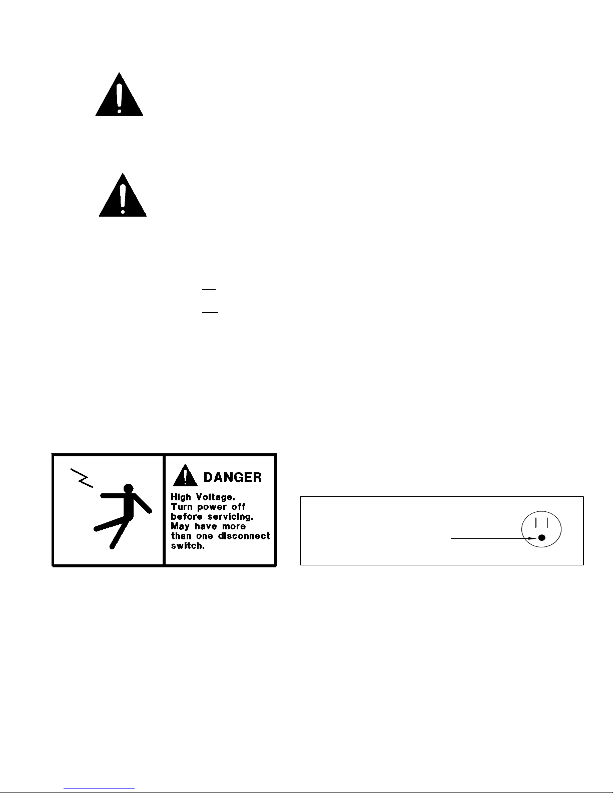
6. When replacing burned out light bars, be sure that the electrical power to the lighting circuit is turned off.
NOTICE TO STORE OWNERS / MANAGERS
Moisture or liquid round or under the c binet is potenti l slip/f ll h z rd for persons w lking by or
working in the gener l re of the c binet. Any c binet m lfunction or housekeeping problem th t cre tes
slip/f ll h z rd round or under the c binet should be corrected immedi tely.
If moisture or liquid is observed around or under the cabinet, an immediate investigation should be made by qualified
personnel to determine the source of the moisture or liquid. The investigation should determine if the cabinet is
malfunctioning or if there is a drainpipe leaking.
MECHANICAL
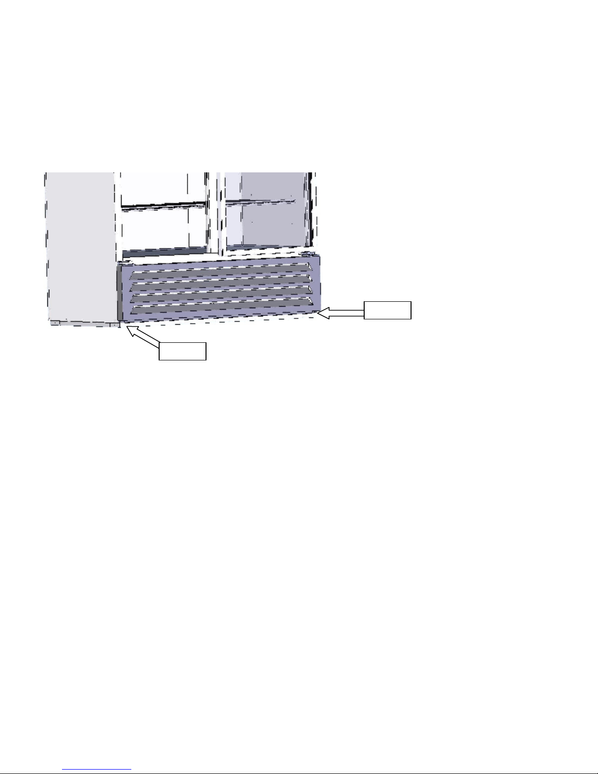
Remove front grille and check refrigeration lines to see that they are free (not touching each other or compressor).
Spin condenser fan blade to see that it is free. Insulate quick connects with pipe insulation to prevent condensation
and/or ice accumulating.
Remove cabinet from crate base and slide into location. Cabinet must be level from side to side and front to back for
correct draining of coil pan and for self-closing doors to operate correctly. Allow minimum of 4” between back of
cabinet and wall and between top of cabinet and ceiling for proper condensing unit air circulation.
To comply with Sanitation requirements the cabinet must be mounted on legs (6” high min.), casters, or the base
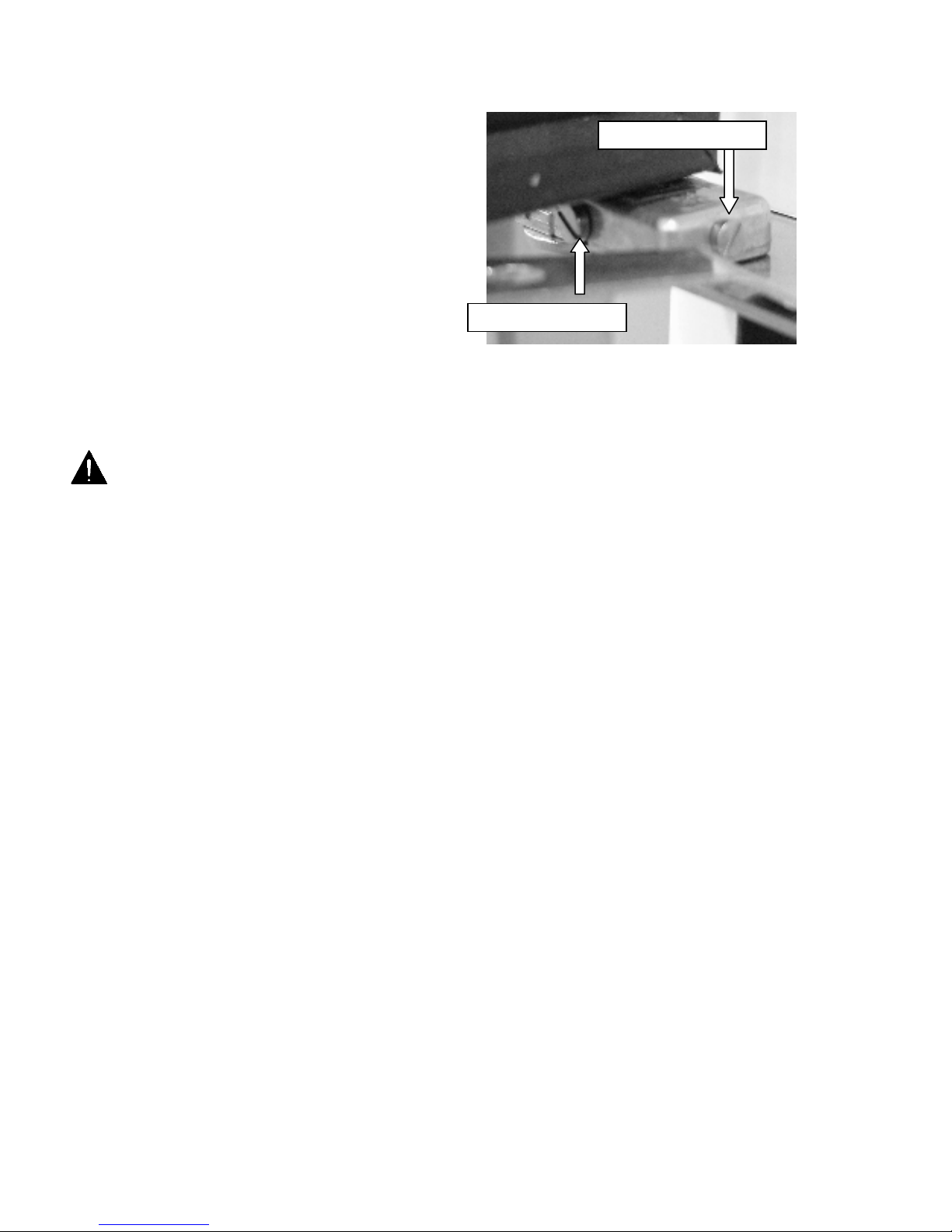
must be sealed to the floor with an N.S.F. listed silicone sealant. When sealing to the floor, leveling bolts can be uses
to assure the cabinet is level before applying silicone sealant.

6/17 Rev. D 57-02400
7
ELECTRICAL
WARNING
Before servicing electric l components in the c se or the doors or door fr mes m ke sure ll
power to c se is off. Alw ys use qu lified technici n.
Check voltage and amps drawn on (TABLE 2) to determine proper line and fuse or circuit breaker size. Check power
supply for low voltage.
For example: If voltage reads “230” with no load, and it drops below “207” when the compressor tries to start, it is an
indication of too small supply wiring or too long to run.
It is recommended that a separate circuit be run for each cabinet to prevent another appliance blowing the fuse or
breaker, causing loss of product.
IMPORTANT
Models (3 door cabinet) are pre-wired internally with a 208-230V NEMA L14-20P plug and should only
be plugged into a NEMA L14-20P recepticle. See wiring diagrams for more details. The cabinet should
be grounded.
LEG / CASTER INSTALLATION
1. Screw legs / casters tightly into the rail
base mounting holes.

6/17 Rev. D 57-02400
8
DOORS
The cabinets have Anthony glass doors
that are equipped with a patented TorqueMaster
hinge system. The doors are easily adjusted using
a flathead screwdriver (Fig.3).
* The tension needs to be checked and set when
first install.
Figure 3
NOTICE
The doors on these c binets re Anti-Fog Gl ss so it is import nt to follow the inform tion below when
cle ning these doors. F ilure to observe the det ils below in cle ning doors will void door supplier
w rr nty.
• Do not use sealants, gaskets, or other materials containing silicone that can contaminate the coating.
• Do not use tape, glue, stickers, attachments, or magic markers on the anti-fog coating.
• Do not use razor blades or any other mechanical device to remove foreign residue or objects directly from
the coated glass.
• Do not use abrasive cleaners or materials on the coated glass. Examples of these cleaners or materials
include Ajax, Brillo, Comet, Scotch Brite, Steel Wool, and Soft Scrub.
• Do not use cleaners or materials on the coated glass that hinder the anti-fog performance by leaving residue
or damaging the surface. Examples of these cleaners include: Armor All, Tilex, Bleach, Windex no-drip,
Windex Wipes, Pledge, or any product containing silicone oils or waxes.
• Recommended cleaners include: Isopropyl Alcohol, reased Lighting, Formula 409 rease & rime,
Formula 409 rease & Surface, Fantastic, Windex Vinegar, Windex Original, Now, Mean reen, or Mr.
Clean (degreasing cleaners).
• Recommended cleaning is with a soft dry or slightly damp towel, or with one of the degreasing cleaners listed
above.
Torque Adjus
tment
Leveling Adjustment

6/17 Rev. D 57-02400
9
GRILL
To remove bottom grill, unscrew the 2 screws on the
bottom for the grill then drop the grill down from the key-slot
hole and pull out. (See Figure 4)
Figure 4
Screw
Screw

6/17 Rev. D 57-02400
10
ELECTRONIC REFRIGERATION CONTROL
Display Lay-out
Compressor When power is first turned on the controller will go through the start-up. After the start-up delay the
compressor comes on. The LED indicator stays on while compressor relay is energized. Display will show actual box
temperature. Picture above is the display layout. The compressor will be cycled off when the actual box temperature
reaches its set point. The compressor indicator will be off.
F n The fans will run during cool mode, cycle during compressor off mode, and off when a defrost is initiated.
When in defrost mode the fans are off until the end of the defrost and the 2 minute drip time has passed. There is 2
minutes delay after a defrost before the fan comes on. If the Evaporator temperature is 35
o
F or below the controller
will override the fan delay. FAN LED indicator is on while fan relay is energized.
Defrost The control uses time defrost with 4 defrost per day. The defrost setting can be reset for special
applications. During defrost the display will show dEF and the defrost LED indicator will be on. The control begins
timing the defrost when power is turned on. Four defrosts per day means it will occur every 6 hours. Example: to
have defrost occur at 8am, 2pm, 8pm, and 2am then power up at one of these four times.
MANUAL DEFROST
Defrosting may also be induced manually by pressing the defrost button for 3 seconds. Once initiated, the unit will go
through a normal defrost and drip time pull down cycle.

6/17 Rev. D 57-02400
11
HOW TO CHANGE THE SETPOINT
HOW TO CHANGE p r meter v lue
LIST OF PARAMETERS
Here is a list of the parameters the value of which can be changed in the programming mode, as well as their ranges.
TABLE 1
Displ y
Symbol P r meter R nge
F ctory
Setting
SP Temperature Set Point SPLSPH -10°F or -15°F
HYS Temperature Differential 1 to 255°F 10°
SPL Minimum Temperature limit setpoint -50SPH -15°F
SPH Maximum Temperature limit setpoint SPH120° 30°F
AHA High Temperature alarm -50120° 45°F
ALA Low Temperature Alarm 50120° -30F
ATD Temperature Alarm Delay 0120min 30min
DFR Number of Defrost Cycle per 24hr 024 4/day
DLI Defrost Termination Temperature -50120° 55°F
DTO Maximum Defrost Duration 1120min 30min
ELECTRICAL CONNECTIONS
The controller is provided with a screw terminal block to connect cables with a cross section up to 2,5 mm
2
. Before
connecting cables make sure the power supply complies with the control’s requirements. Separate the probe cables
from the power supply cables, and the outputs and the power connections. Do not exceed the maximum current
allowed on each relay. In case of heavier loads use a suitable external relay or contactor.
PROBE CONNECTIONS
The probes shall be mounted with the bulb upwards to prevent damage due to casual liquid infiltration. It is
recommended to place the thermostat probe away from air streams to correctly measure the average room
temperature. Place the defrost termination probe among the evaporator fins in the coldest place, where most ice is
formed, far from heaters or from the warmest place during defrost to prevent premature defrost termination.

6/17 Rev. D 57-02400
12
FINAL CHECK LIST
A. Check operating pressures.
B. Check electrical requirements of unit to
supply voltage.
C. Set temperature control for desired
temperature range.
D. Check sight glass for proper refrigerant
charge, if provided.
E. Check system for proper defrost settings and
operation.
F. Check condensing unit for vibrating or
rubbing tubing. Dampen and clamp as
required.
. All valves should be completely opened
counter-clockwise.
H. Check packing nuts on all service valves.
I. Replace all service valve caps and latch unit
covers.
J. Check and set the door tension at the Torque
Adjustment
SERVICE INSTRUCTION
1. High head pressure and high back pressure:
A. Condenser coil clogged or restricted
B. Condenser fan motor defective.
C. Air discharge in rear of cabinet restricted.
2. Low back pressure and low head pressure:
A. Restriction in system.
B. Refrigerant undercharged.
C. Leak in system
3. Pressure normal – cabinet warm:
A. Coil blocked with frost (see #4).
B. Refrigerant undercharged.
C. Control set too warm.
4. Cabinet not cycling – coil blocked with frost:
A. Defective temperature controller.
B. Refrigerant overcharged.
C. Location too hot.
D. Condenser clogged.
E. Condenser fan motor defective.
F. Defrost heater not operating.
5. Compressor starts and runs – but cycles on overload:
A. Low voltage
B. Relay defective.
C. Overload defective.
D. High head pressure (see #1).

6/17 Rev. D 57-02400
13
Temper ture sensor, defrost he ter nd f n motor repl cement
Before making any change, technician should:
1. Disconnect power to the cabinet
2. Remove screws from venturi and pull down
To change a temperature sensor (cabinet sensor or defrost sensor), simply disconnect the sensor wires from the
controller and replace the new sensor in the original position. Use plastic tie to tighten the zone sensor. Insert the
sensor for defrost termination firmly into top-center of the evaporator coil, in between the fins. Make sure the
sensor wires do not touch or are not close to any heater rods.
To change defrost heater – remove screws from drain pan and pull down – remove screws from coil mounting
straps – spring straps open – remove heater shield – pull heater out of slots in coil fins.
To change fan motor – disconnect fan motor leads – remove screws from fan guards and motor mounts.

6/17 Rev. D 57-02400
14
PART LIST
The table below gives componet part numbers. Use this chart when ordering replacement parts for your MBGFP
cabinets. Always Advise Cabinet Serial Number When Ordering Parts
MBGFP23-HG MBGFP27-HG MBGFP48-HG MBGFP74-HG
Ballast 23-01709 23-01709 23-01709 23-01709
Bulb 23-01576 23-01576 23-01575 23-01577
Lamp Holder 23-50562 23-50562 23-50562 23-50562
LED Light Bar ( ingle) 23-01924 (R) 23-01924(R) NA 23-01924(R)
LED Light Bar (Double) NA NA 23-01925 (C) 23-01925 (C)
Female Door Plug (if required) 21-00568 21-00568 21-00568 21-00568
Light witch 23-50793 23-50793 23-50793 23-50793
Expansion Valve 09-10407 09-10407 09-10408 09-10408
Evaporator Coil 07-14098 07-14098 07-14099 07-14100
Evaporator Fan Blade 15-13106 15-13106 15-13106 15-13106
Evaporator Fan Motor 13-13279 13-13279 13-13279 13-13279
Evaporator Fan Guard 25-01324 25-01324 25-01324 25-01324
Defrost Heater 17-09568 17-09568 17-09569 17-09570
Drain Line Heater 17-00404 17-00404 17-00404 17-00404
Defrost Heater afety 19-01164 19-01164 19-01164 19-01164
Compressor 03-15192 03-15192 03-14902 03-14898
Condenser Coil 07-14088 07-14088 07-14089 07-14089
Condenser Fan Motor 13-13101 13-13101 13-13101 13-01283
Condenser Fan Blade 15-13093 15-13093 15-13093 15-13093
Drier 09-09171 09-09171 09-09171 09-09171
Thermometer 44-00963 44-00963 44-00963 44-00963
LAE Controller 19-14243 19-14243 19-14243 19-14243
LAE ensor T1 19-14244 19-14244 19-14244 19-14244
LAE ensor T2 19-14245 19-14245 19-14245 19-14245
Door - LH 31-03925 31-03926 31-03927 31-03927
Door - RH 31-03929 31-03930 31-03928 31-03928
Pilaster 33-01408 33-01408 33-01408 33-01408
Pilaster Clip 33-01011 33-01011 33-01011 33-01011
Wall Guard 25-01376 25-01376 25-01376 25-01376
helf ( ides) 33-01812 (W)
33-01813 (B)
33-01807 (W)
33-01808 (B)
33-01805 (W)
33-01806 (B
33-01805 (W)
33-01806 (B)
helf (Middle) NA NA NA 33-01807(W)
33-01808 (B)
helf (Bottom ides) NA 33-01402 (W)
33-01590 (B)
33-01453 (W)
33-01606 (B)
33-01453 (W)
33-01606 (B)
helf (Bottom Center) NA NA NA 33-01453 (W)
33-01606 (B)

6/17 Rev. D 57-02400
15
Accessories (Includes HD Models)
Description
MBGFP23-HG MBGFP27-HG MBGFP48-HG MBGFP74-HG
Casters (4) 2” Diameter A039-11140 A039-11140 A039-11140
Casters (6) 2” Diameter A044-11140
Legs 6” A039-11170 A039-11170 A039-11170 A044-11170
SALE AND DISPOSAL
OWNER RESPONSIBILITY
If you sell or give away your cabinet; you must make sure that all safety labels and the Installation - Service Manual
are included with it. If you need replacement labels or manuals, factory will provide them free. Contact the
customer service department at (800) 684-8988.
The customer service department should be contacted at the time of sale or disposal of your cabinet so records
may be kept of its new location
If you sell or give away your cabinet and you evacuate the refrigerant charge before shipment, factory recommends
that the refrigerant charge be properly recovered in compliance with section 608 of the Clean Air Act effective
November 1995 and in accordance with all applicable local, regional, or national standards.
The customer service department at Master-Bilt should be contacted at the time of sale or disposal of your cabinet
so records may be kept of its new location.

6/17 Rev. D 57-02400
16

6/17 Rev. D 57-02400
17

6/17 Rev. D 57-02400
18
This manual suits for next models
4
Table of contents
Other Master Bilt Freezer manuals