master mechanic 176578 User manual

20 VOLT LI-ION IMPACT DRIVER
176578
Owner’s Manual
Manufactured For and Distributed By
True Value®Company, Chicago, IL
©2014 True Value Company
Made in China
PRODUCT SPECIFICATIONS
IMPACT DRIVER
Speed:
0–3,000 RPM (no load)
Impact speed:
0–3,500 BPM
Torque:
1,400 in/lbs
Hex drive:
1/4" Quick release
Weight:
2 lb 10 oz (1.19 kg) without battery
BATTERY & CHARGER
Battery voltage:
20V Li-ion (Maximum charged battery
voltage, measured without load, is 20V
with a nominal value of 18V)
18V Ni-Cad
Charger:
1 Hour, Class 2
Will charge battery types:
20V Li-ion #153928
18V Ni-Cad #134458
Charger input:
120V AC, 60 Hz, 60W
Charger output:
18V DC, 2 AMP for Ni-Cad batteries
20V DC, 2 AMP for Li-ion batteries
Replacement battery:
20V Li-ion #178598
Need Assistance?
Call us on our toll free customer support line:
1-866-349-8665 Monday –Friday from 9am to 5pm Eastern Standard Time
Technical questions
Replacement parts
Parts missing from package

2
Product specifications ………….………………………………………………………………...
1
California Prop 65 warning ………………………………………………………………………
2
Table of contents ……………………………………………………………………...………....
2
General safety warnings ……………………………………………………………..……….....
3–4
Safety symbols ……………………………………………………………………………………
3
Eye, ear, & lung protection …………………………………………………………………......
4
Electrical safety ……………………………………………………………………….………....
4
Power tool safety ……………………………………………………………………...………....
5–6
Ventilation warning ……………………………………………………………………………….
5
General warning ………………………………………………………………………………....
5
Work area safety ………………………………………………………….…………..………....
5
Electrical safety ……………………………………………………………………….………....
5
Personal safety ………………………………………………………………………..………....
5–6
Power tools use and care ……………………………………………………………………....
6
Service …………………………………………………………………………………………....
6
Specific safety rules …………………………………………………………………..………....
7
Battery & charger safety …………………………………………………………………………
8
Battery pack recycling ……………………………………………………………………………
8
Symbols ………………………………………………………………………………..………....
9
Know your impact driver ……………………………………………………………………......
10
Assembly and operating ……………………………………………………………..………....
11–16
Forward/reverse switch ………………………………………………………………………….
13
Variable-speed trigger switch …………………………………………………………………...
13
Tightening and removing fasteners …………………………………………………………….
13
LED worklight ……………………………………………………………………………………..
13–14
Preparing screw holes …………………………………………………………………………...
14
Driving screws …………………………………………………………………………………….
14–15
Installing nut drivers for 3/16” to 3/8” nuts ……………………………………………………..
15
Installing impact sockets for 7/16” to ¾” nuts ………………………………………………….
15
Removing nuts ……………………………………………………………………………………
16
Maintenance …………………………………………………………………………..………....
17
Exploded view …………………………………………………………………………………....
18
Parts list ………………………………………………………………………………..………....
19
Warranty ……………………………………………………………………….………………....
20
CALIFORNIA PROP 65 WARNING
Warning: Some dust created by power sanding, sawing, grinding, drilling, and other
construction activities contains chemicals known to the State of California to cause cancer and
birth defects or other reproductive harm. Some examples of these chemicals are:
lead from lead-based paints,
crystalline silica from bricks and cement and other masonry products, and
arsenic and chromium from chemically treated lumber.
Your risk from exposure to these chemicals varies, depending on how often you do this type of
work. To reduce your exposure, work in a well-ventilated area and with approved safety
equipment, such as dust masks that are specially designed to filter out microscopic particles.
Warning: This product contains chemicals known to the State of California to cause cancer
and birth defects or other reproductive harm.
!
!
TABLE OF CONTENTS

3
READ AND UNDERSTAND ALL SAFETY AND OPERATIONAL
INSTRUCTIONS. Failure to follow the safety rules listed below and other basic
safety precautions may result in serious personal injury. KEEP THIS MANUAL,
SALES RECEIPTS AND APPLICABLE WARRANTY FORMS FOR FUTURE
REFERENCE.
Safety Symbols
The purpose of safety symbols is to alert you of the potential safety RISKS.
Recognize and understand them. Follow the instructions provided.
SYMBOL
MEANING
Failure to obey a DANGER safety alert WILL result in
serious personal injury or death to you or to others.
Always obey all messages following this symbol to
reduce the risk of serious personal injury or death.
Failure to obey a WARNING safety alert MAY result in
serious personal injury or death to you or to others.
Always obey all messages following this symbol to
reduce the risk of potential serious personal injury or
death.
Failure to obey a CAUTION safety alert MAY result in
personal injury or property damage to you or to others.
Always obey all messages following this symbol to
reduce the risk of personal injury or property damage.
Failure to obey a NOTICE or a CAUTION (without a
safety alert) MAY result in property damage to you or to
others. Always obey all messages following this
symbol to reduce the risk of property damage.
GENERAL SAFETY WARNINGS
This instruction manual includes the following:
General Safety Rules
Specific Safety Rules and Symbols
Functional Description
Assembly
Operation
Maintenance
Accessories
SAVE THESE INSTRUCTIONS FOR REFERENCE

4
ALWAYS WEAR EYE PROTECTION THAT CONFORMS
WITH CSA REQUIREMENTS or ANSI SAFETY
STANDARD Z87.1
FLYING DEBRIS can cause permanent eye damage.
Prescription eyeglasses ARE NOT a replacement for
proper eye protection.
Non-compliant eyewear can cause serious injury if
broken during the operation of a power tool.
Use hearing protection, particularly during extended
periods of operation of the tool, or if the operation is
noisy.
WEAR A DUST MASK THAT IS DESIGNED TO BE
USED WHEN OPERATING A POWER TOOL IN A
DUSTY ENVIRONMENT.
Dust that is created by power sanding, sawing, grinding,
drilling, and other construction activities may contain
chemicals that are known to cause cancer, birth defects,
or other genetic abnormalities. These chemicals include:
Lead from lead-based paints, Crystalline silica from bricks,
cement, and other masonry products, Arsenic and
chromium from chemically treated lumber
The level of risk from exposure to these chemicals varies,
according to how often this type of work is performed. In
order to reduce exposure to these chemicals, work in a
well-ventilated area, and use approved safety equipment,
such as a dust mask that is specifically designed to filter
out microscopic particles.
To avoid electrical hazards, fire hazards or damage to
the tool, use proper circuit protection.
This tool is wired at the factory for 120 V AC operations. It
must be connected to a 120 V AC, 15 A circuit that is
protected by a time-delayed fuse or circuit breaker. To
avoid shock or fire, replace power cord immediately if it is
worn, cut or damaged in any way.
GENERAL SAFETY WARNINGS
SAVE THESE INSTRUCTIONS FOR REFERENCE

5
WARNING: Read all safety warnings
and instructions. Failure to follow the warnings
and instructions may result in electric shock, fire
and/or serious injury.
Save all warnings and instructions for future
reference.
Work area safety
Keep work area clean and well lit. Cluttered or
dark areas invite accidents.
Do not operate power tools in explosive
atmospheres, such as in the presence of
flammable liquids, gases or dust. Power tools
create sparks which may ignite the dust or
fumes.
Keep children and bystanders away while
operating a power tool. Distractions can cause
you to lose control.
Electrical safety
Power tool plugs must match the outlet.
Never modify the plug in any way. Do not
use any adapter plugs with earthed
(grounded) power tools. Unmodified plugs and
matching outlets will reduce risk of electric
shock.
Avoid body contact with earthed or
grounded surfaces such as pipes, radiators,
ranges and refrigerators. There is an
increased risk of electric shock if your body is
earthed or grounded.
Do not expose power tools to rain or wet
conditions. Water entering a power tool will
increase the risk of electric shock.
Do not abuse the cord. Never use the cord
for carrying, pulling or unplugging the power
tool. Keep cord away from heat, oil, sharp
edges or moving parts. Damaged or
entangled cords increase the risk of electric
shock.
When operating a power tool outdoors, use
an extension cord suitable for outdoor use.
Use of a cord suitable for outdoor use reduces
the risk of electric shock.
If operating a power tool in a damp location
is unavoidable, use a residual current device
(RCD) protected supply. Use of a ground fault
circuit interrupter (GFCI) reduces the risk of
electric shock.
Personal safety
Stay alert, watch what you are doing and use
common sense when operating a power tool.
Do not use a power tool while you are tired
or under the influence of drugs, alcohol or
medication. A moment of inattention while
operating power tools may result in serious
personal injury.
Use personal protective equipment. Always
wear eye protection. Protective equipment
such as dust mask, non-skid safety shoes, hard
hat, or hearing protection used for appropriate
conditions will reduce personal injuries.
Prevent unintentional starting. Ensure the
switch is in the off-position before
connecting to power source and/or battery
pack, picking up or carrying the tool.
Carrying power tools with your finger on the
switch or energizing power tools that have the
switch on invites accidents.
POWER TOOL SAFETY
!
WARNING: Ventilation openings in batteries and chargers must always be
open to allow cooling air to circulate freely. Air vents that are blocked,
restricted or covered may result in the battery or charger overheating.
Overheating may lead to damage to the tool or cause a fire, resulting in
possible serious injury.
!

6
Remove any adjusting key or wrench before
turning the power tool on. A wrench or a key
left attached to a rotating part of the power tool
may result in personal injury.
Do not overreach. Keep proper footing and
balance at all times. This enables better
control of the power tool in unexpected
situations.
Dress properly. Do not wear loose clothing
or jewelry. Keep your hair, clothing and
gloves away from moving parts. Loose
clothes, jewelry or long hair can be caught in
moving parts.
If devices are provided for the connection of
dust extraction and collection facilities,
ensure these are connected and properly
used. Use of dust collection can reduce dust-
related hazards.
Power tool use and care
Do not force the power tool. Use the correct
power tool for your application. The correct
power tool will do the job better and safer at the
rate for which it was designed.
Do not use the power tool if the switch does
not turn it on and off. Any power tool that
cannot be controlled with the switch is
dangerous and must be repaired.
Disconnect the plug from the power source
and/or the battery pack from the power tool
before making any adjustments, changing
accessories, or storing power tools. Such
preventive safety measures reduce the risk of
starting the power tool accidentally.
Store idle power tools out of the reach of
children and do not allow persons unfamiliar
with the power tool or these instructions to
operate the power tool. Power tools are
dangerous in the hands of untrained users.
Maintain power tools. Check for
misalignment or binding of moving parts,
breakage of parts and any other condition
that may affect the power tool’s operation. If
damaged, have the power tool repaired
before use. Many accidents are caused by
poorly maintained power tools.
Keep cutting tools sharp and clean. Properly
maintained cutting tools with sharp cutting
edges are less likely to bind and are easier to
control.
Use the power tool, accessories and tool bits
etc. in accordance with these instructions,
taking into account the working conditions
and the work to be performed. Use of the
power tool for operations different from those
intended could result in a hazardous situation.
Hold power tools by insulated gripping
surfaces when performing an operation
where the cutting tool may contact hidden
wiring or its own cord. Contact with a "live"
wire will make exposed metal parts of the tool
"live" and shock the operator.
Hold power tool by insulated gripping
surfaces, when performing an operation
where the fastener may contact hidden
wiring or its own cord. Fasteners contacting a
″live″ wire may make exposed metal parts of the
power tool ″live″ and could give the operator an
electric shock.
Service
Have your power tool serviced by a qualified
repair person using only identical
replacement parts. This will ensure that the
safety of the power tool is maintained.
POWER TOOL SAFETY

7
WARNING: This product contains
chemicals known to the State of California to
cause cancer and birth defects or other
reproductive harm.
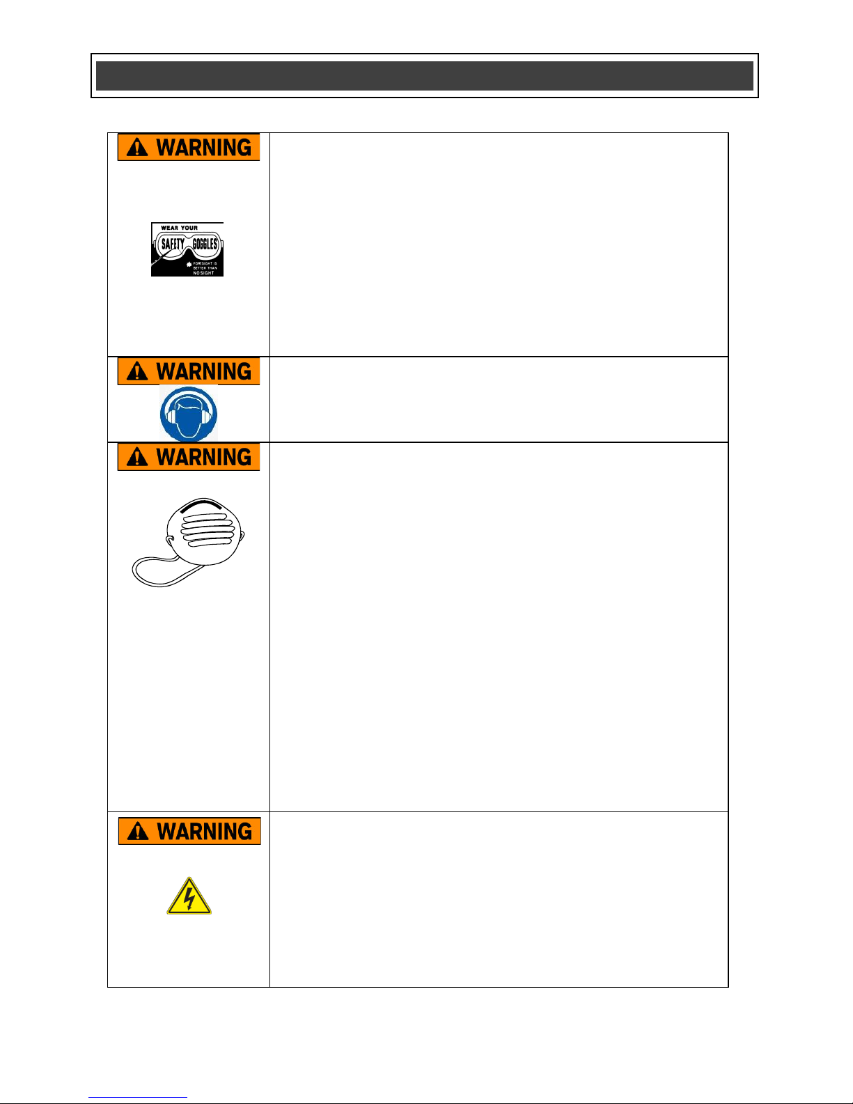
WARNING: Some dust created by power
sanding, sawing, grinding, drilling, and other
construction activities contain chemicals
known to cause cancer, birth defects, or
other reproductive harm. Some samples of
these chemicals are:
lead from lead-based paints,
crystalline silica from bricks and
cement and other masonry products,
and
arsenic and chromium from
chemically-treated lumber.
Your risk from these exposures varies,
depending on how often you do this type of
work. To reduce your exposure to these
chemicals: work in a well-ventilated area, and
work with approved safety equipment, such as
those dust masks that are specially designed to
filter out microscopic particles.
Always wear eye protection. Any
power tool can throw foreign
objects into your eyes and cause
permanent eye damage. ALWAYS
wear safety goggles (not glasses) that comply
with ANSI safety standard Z87.1. Everyday
glasses have only impact resistant lenses. They
ARE NOT safety glasses.
WARNING: Glasses or goggles not in
compliance with ANSI Z87.1 could cause
serious injury when they break.
Always use hearing protection when operating
the impact driver.
Use only impact sockets and accessories that
are designed for use with an impact driver. Do
not use chrome plated sockets and accessories.
Chrome plated sockets and accessories are
designed for hand use only and MUST NOT be
used with an impact driver. They may shatter
and possibly cause serious injury.
Before each use, check the impact sockets and
accessories for excessive wear or cracks. Worn
or damaged sockets or accessories may shatter
and possibly cause serious injury. Worn
accessories may allow the socket to come off
during operation of the impact driver.
After installing any accessory in the hex drive,
pull outward on the accessory to ensure it is
properly installed and cannot be pulled out of
the hex drive.
Never use the impact driver as a torque wrench.
Always use a torque wrench to adjust the
fastener to the specified torque.
Keep the impact driver handle and body clean
and free of oil and grease. Always use a clean
dry cloth when cleaning. Do not use solvents,
brake fluid, gasoline or other petroleum products
to clean the tool. They will damage the tool.
Do not wear neckties or loose clothing.
When wearing gloves, they must be tight fitting
and slip resistant type. Leather gloves offer the
best protection.
Always use two hands when operating the
impact driver. Use one hand on the handle and
the other on the front of the tool body.
Never place your hand so it is touching the
socket or accessory when the tool is turned ON.
Your hand could be seriously injured.
Always remove the battery from the tool before
installing or removing any socket or accessory.
Be ready for components to shift when removing
any fastener. The speed of the fastener removal
could cause unexpected shifting of the
components.
SPECIFIC SAFETY RULES
!
!
!

8
WARNING: Only use the diagnostic
charger supplied with this kit to charge a
20V Li-ion #153928 battery or an 18V Ni-Cd
#134458 battery. Charging any other
batteries may damage the charger and
possibly cause serious injury.
Do not store or carry the battery in a manner in
which metal objects could contact the exposed
metal end. Do not place the battery in aprons,
pockets, drawers, etc. with loose nails, screws,
keys etc. The battery could short circuit causing
a fire, personal injury or damage to the battery.
Never attempt to open the battery for any
reason. If the housing of the battery breaks or
cracks, immediately discontinue use and do not
recharge.
Do not charge the battery if it is wet or shows
any evidence of corrosion.
A small leakage from the battery may occur
under extreme usage, charging or temperature
conditions. This does not indicate a failure.
However, if the outer seal is broken and this
leakage gets on your skin, follow these steps:
1. Wash immediately with soap and water.
2. Neutralize with a mild acid such as lemon
juice or vinegar.
3. If liquid gets into your eyes, flush
immediately with clean water for a
minimum of 10 minutes and seek medical
attention.
NOTE: The battery liquid is slightly acidic.
Do not incinerate the battery. It can explode in a
fire.
To preserve our natural resources, please
recycle or dispose of batteries properly.
The batteries charged by this charger may
contain chemicals and metals that are harmful
to the environment. Never dispose of re-
chargeable batteries in your normal household
garbage or in landfill sites as they will add to the
pollution of the environment.
Do not use an extension cord. Plug the charger
cord directly into an electrical outlet.
Use the charger only in a standard
120V, 60 Hz electrical outlet.
Do not use the charger in wet or damp
conditions. It is intended for indoor use only. Do
not use the charger near sinks or
tubs. Do not immerse the charger in water.
Do not allow the cord to hang over the edge of a
table or counter or touch hot surfaces. The
charger should be placed away from sinks and
hot surfaces.
Do not use the charger to charge any batteries
other than the cordless drill batteries. Other
batteries may explode.
Do not operate charger if the cord or plug is
damaged. Replace the damaged cord and plug
immediately.
Do not operate the charger if it has received a
sharp blow, been dropped or otherwise
damaged in any way. Have a qualified
technician examine the charger and repair it if
necessary. Do not disassemble the charger.
Do NOT charge the batteries when the work
area or the battery temperature is at or below 0°
C (32° F) or above
45° C (113° F).
Unplug the charger when not in use and before
cleaning or maintenance.
BATTERY & CHARGER SAFETY
!
BATTERY PACK RECYCLING

9
This symbol designates that this tool is listed
with U.S. requirements by ETL Testing
Laboratories, Inc.
Conforms to UL Std. 60745-1, and 60745-2-2.
3042597
JD507420
V
Volts
A
Amperes
Hz
Hertz
W
Watts
kW
Kilowatts
Microfarads
L
Litres
kg
Kilograms
H
Hours
N/cm2
Newtons per square
centimetre
Pa
Pascals
BPM
Beats per minute
Min
Minutes
S
Seconds
or a.c.
Alternating current
Three-phase alternating
current
Three-phase alternating
current with neutral
Read all safety warnings
and instructions
Direct current
No load speed
Alternating or direct
current
Class II construction
Splash-proof
construction
Watertight construction
Protective grounding at
grounding terminal,
Class I tools
Revolutions or
reciprocations per
minute
Diameter
Off position
Directional arrow
Warning symbol
Wear your safety
glasses
Wear dust mask
Wear hearing protection
Risk of fire
SYMBOLS
WARNING: Some of the following symbols may appear on the impact
driver. Study these symbols and learn their meaning. Proper interpretation of
these symbols will allow for more efficient and safer operation of this tool.
!

10
KNOW YOUR IMPACT DRIVER
Forward /
reverse switch
Battery
#178598
Battery release
button
Quick release
hex drive
Air vents
Variable speed
trigger switch
Single ended
screwdriver bits
#2
LED worklight
Battery charger
Red
LED
Green
LED
Air vents
Air vents

11
CHARGING THE BATTERY PACK
1. Place the battery charger (1) in a dry
location near a 110–120V 60 Hz electrical
outlet (Fig. 1).
2. Turn the battery (2) upside down and slide
it onto the charger.
NOTE: Make sure the grooves (3) in the
sides of the battery slide over the matching
tabs on the charger (4) until the battery
latch “clicks” into place.
3. Plug the battery charger into the 110–120V
60 Hz wall receptacle.
NOTES:
a) When the charger is plugged into the wall
receptacle and NO battery is on the charger, the
green indicator light (5) will turn ON indicating
the charger is “live”.
b) When a discharged battery is installed on the
charger, the green indicator light will turn OFF
and the red indicator light (6) will FLASH. The
flashing red indicator light indicates the battery
is being charged.
c) If the red indicator light does not come ON,
check to make sure battery pack is slid fully onto
the charger and the electrical outlet is working
properly.
d) See Fig. 2 at right for other indicator light
functions.
e) A new battery pack or one that is completely
run down should be charged for 2 hours. After
normal use, a battery pack should be fully
charged in about one hour.
f) It is normal for the battery charger to hum and
be warm to the touch during operation.
g) If the battery pack does not charge properly,
check to make sure the electrical outlet is “live”.
h) Do NOT charge batteries when the work area
or the battery temperature is at or below 0°C
(32° F) or above 45°C (113° F).
ASSEMBLY AND OPERATING
Green
Light
Red
Light
Battery
Inserted
Into
Charger
Charging
Status
ON
OFF
NO
Charger
connected
to power
supply
OFF
Flashing
YES
Battery
being
charged
ON
OFF
YES
Battery fully
charged
OFF
ON
YES
Battery
defective or
bad contact
ON
ON
YES
Battery too
hot or too
cold to be
charged
Fig. 2
Fig. 1

12
INSTALLING THE BATTERY PACK IN THE
IMPACT DRIVER
1. Remove the discharged battery pack (1)
from the tool by pressing the battery
release button (2) on the rear of the battery
downward (Fig. 3) and pulling the battery
pack out of the tool handle (3) (Fig. 4).
2. Insert the fully charged battery pack into
the matching slots in the rear of the tool
handle where the discharged battery pack
has been removed.
NOTE: The battery release button will
“click”into place when the battery pack is
fully installed.
WARNING: Do not immerse battery
pack in water. Sudden cooling could cause a
hot battery to explode or leak.
ON-BOARD SCREWDRIVER BIT STORAGE
Convenient on-board screwdriver bit storage (1)
is provided on the drill/driver handle base
(Fig. 5).
INSTALLING SCREWDRIVER BITS
WARNING: Use only screwdriver bits,
sockets and accessories that are designed
for use with an impact driver. Do not use
chrome plated sockets and accessories.
Chrome plated sockets and accessories are
designed for hand use only and MUST NOT be
used with an impact driver. They may shatter
and possibly cause serious injury.
WARNING: Always remove the battery
from the tool before changing any sockets, bits
or accessories. You may injure your hand if the
tool is started accidentally.
1. To install a screwdriver bit, pull outward on
the hex drive sleeve (1) (Fig. 6). While
holding the hex drive sleeve out, insert the
bit (2) fully into the hex drive and then
release the outer sleeve.
2. When the hex drive sleeve is released, pull
outward on the bit to ensure the retaining
ball inside the hex drive is engaged with
the groove in the bit (3) to prevent the bit
from sliding out of the hex drive.
3. To remove the bit, pull outward on the hex
drive sleeve and pull the bit out of the hex
drive.
WARNING: Never use a screwdriver bit or
nut driver that does NOT have the locking
groove. These accessories will not be
adequately held in the hex drive and could come
loose and possibly injure the operator.
ASSEMBLY AND OPERATING
!
!
!
!
Fig. 3
Fig. 4
Fig. 5
Fig. 6

13
Fig. 8
FORWARD/REVERSE SWITCH
This impact driver is equipped with a
forward/reverse button (1) (Fig. 7).
1. To operate the impact driver in the forward
direction, press the forward/reverse button
to the LEFT for driving screws or tightening
nuts.
2. To operate the impact driver in the reverse
direction, press the forward/reverse button
to the RIGHT for removing screws or
removing nuts.
NOTE: Never press the forward/reverse button
while the tool it turned ON. Damage to the tool
will result.
VARIABLE-SPEED TRIGGER SWITCH
This impact driver is equipped with a variable-
speed ON/OFF trigger switch.
1. To start impact driver, gently squeeze the
trigger switch (2) (Fig. 8).
NOTE: The impact driver will turn at its slowest
speed when the trigger switch is depressed
slightly. The impact driver will turn at its fastest
speed when the trigger switch is fully
depressed.
2. To stop the impact driver, release the
trigger switch.
NOTE: Operating the tool at a slow speed for an
extended period of time may cause the switch to
overheat. If either the switch gets hot, stop using
the impact driver and allow the tool to cool for at
least 15 minutes.
TIGHTENING AND REMOVING FASTENERS
The most common uses for the impact driver
are to drive or remove screws and to tighten or
loosen small nuts.
The principles for operating the impact driver
are the same for most applications. For
illustrative purposes, driving a wood screw is
shown.
LED WORK LIGHT
The LED work light (3) will automatically turn ON
when the trigger switch (2) is squeezed (Fig. 9).
It will automatically turn OFF when the trigger
switch is released.
ASSEMBLY AND OPERATING
For safety reasons, the operator must
read the sections of this Owner’s Manual
entitled “GENERAL SAFETY WARNINGS”,
“POWER TOOL SAFETY”, “SPECIFIC
SAFETY RULES”, “BATTERY &
CHARGER SAFETY” and “SYMBOLS”
before using this impact driver.
Verify the following every time the impact
driver is used:
1. Safety glasses, safety goggles, or
face shield are being worn.
2. Hearing protection is being worn.
3. Socket, nut driver or screwdriver bit
is the correct size and is “impact
driver”rated.
4. Socket, nut driver or screwdriver bit
is in good condition.
Failure to observe these safety rules will
significantly increase the risk of injury.
WARNING
!
Fig. 7

14
PREPARING SCREW HOLES
It is important to prepare screw holes before
attempting to fasten two pieces of wood
together. Proper preparation will make screws
drive easier and prevent misaligned
components, stripped screw heads, splitting and
separating of wood components.
1. Clamp the components that are to be
screwed together in their desired position
(Fig. 10).
2. Drill a pilot hole (1) through the outer piece
(2) and into the inner piece (3). Drill the
hole 2/3 the diameter of the smooth portion
of the screw shank.
NOTE: If the wood is soft, drill the hole 2/3 the
length of the screw. If the wood is hard, drill the
hole the full length of the screw.
3. Remove the clamp from the two pieces to
be screwed together.
4. Enlarge the hole (1) in the outer piece (2)
so it is the same size as the smooth portion
of the screw shank (Fig. 11).
5. If using a flat head screw, counter-sink the
hole (4) so the head of the screw will be
flush with the surface when fully driven into
place.
DRIVING SCREWS
When driving screws, care must be taken to use
a bit that correctly fits the head of the screw
being driven. Be sure to use the largest bit size
that will properly fit into the head of the screw.
The bit must also be in good condition and not
worn so it will drive screws without slipping out
of the screw head.
Always hold the impact driver with two hands
when driving and removing screws to provide
the best possible control over the tool.
1. Select the correct screwdriver bit for the
screw being driven.
2. Insert the bit into the hex drive
(Fig. 6).
3. Set the forward/reverse button to the LEFT
for driving screws (Fig. 7).
4. Insert the screwdriver bit (1) fully into the
screw head (2) (Fig. 12).
ASSEMBLY AND OPERATING
Fig. 11
Fig. 10
Fig. 9

15
Fig. 13
Fig. 14
DRIVING SCREWS –cont’d
5. While holding the screwdriver firmly against
the screw with both hands and the bit
aligned with the screw, squeeze the trigger
switch and drive the screw.
6. When the screw is driven to the correct
depth, release the switch and the impact
driver will stop.
NOTE: As the screw is driven into the
wood, the torque required to completely
drive the screw into the wood will increase.
The impact function will allow you to
continue driving the screw until it is fully
nested in the countersunk area.
7. Release the trigger as soon as the screw is
driven to the desired depth. Failure to
release the trigger at this point will result in
an overdriven screw and possibly twist the
head off the screw.
NOTE: To remove screws, follow the same
general procedure as for driving screws.
8. Push the forward/reverse button to the
RIGHT for removing screws.
9. Insert the bit fully into the screw head.
10. Hold the impact driver and bit firmly against
the screw head and squeeze the trigger
switch.
NOTE: The impact action will allow you to
remove tight screws.
INSTALLING NUT DRIVERS FOR
3/16" to 3/8" NUTS
1. Select the correct nut driver size.
2. Insert the hex end (1) into the hex drive (2)
(Fig. 13).
NOTE: See Fig. 6 for complete procedure.
INSTALLING IMPACT SOCKETS FOR
7/16" to 3/4" NUTS
1. Insert the hex end of the socket adapter (1)
into the hex drive (2) (Fig. 14).
2. Select the correct socket size.
3. Push the square end of the socket (3) onto
the matching square end of the adaptor (4).
NOTES:
a) See Fig. 6 for complete procedure.
b) Make sure the socket is fully installed
onto the square portion of the adapter.
ASSEMBLY AND OPERATING
This impact driver may be used with nut
drivers and impact sockets. Although these
accessories are NOT included with this tool,
they may be purchased separately.
WARNING: Nut drivers, socket
adaptor and sockets MUST be impact rated
and include the ANSI locking groove.
!
Fig. 12

16
REMOVING NUTS
1. Press the forward/reverse button to the
RIGHT for removing nuts (Fig. 7).
2. Place the socket fully onto the nut.
3. Hold the nut driver socket and impact
driver firmly against the nut with both
hands. With the nut driver aligned with the
nut, squeeze the trigger switch to start the
impact driver and remove the nut.
NOTE: When removing fasteners, do not allow
the impact driver to operate more than 5
seconds unless the fastener begins to turn. If
the fastener fails to turn within 5 seconds,
reverse the direction of rotation and operate the
impact driver in a forward direction on the
fastener for a few seconds. Now switch back to
reverse direction and remove the fastener. This
procedure will usually break loose seized or
"frozen" fasteners.
WARNING: Operating the impact driver for
more that 5 seconds at a time on a seized or
“frozen”fastener will place severe stress on the
impact driver and cause damage. It may also
break the fastener.
ASSEMBLY AND OPERATING
!

17
GENERAL
WARNING: When servicing, use only
identical replacement parts. The use of any
other part may create a hazard or cause
product damage.
DO NOT use solvents when cleaning plastic
parts. Plastics are susceptible to damage from
various types of commercial solvents and may
be damaged by their use. Use a clean cloth to
remove dirt, dust, oil, grease etc.
WARNING: Do not allow brake fluids,
gasoline, petroleum-based products,
penetrating oils, etc. to come into contact
with plastic parts. They contain chemicals
that can damage, weaken or destroy plastic.
DO NOT abuse power tools. Abusive practices
can damage the tool and the workpiece.
WARNING: DO NOT attempt to modify
tools or create accessories. Any such
alteration or modification is misuse and
could result in a hazardous condition leading
to possible serious injury. It will also void
the warranty.
LUBRICATION
All of the bearings in this tool are lubricated with
a sufficient amount of high-grade lubricant for
the life of the unit under normal conditions.
Therefore, no further lubrication is required.
BATTERY PACK REMOVAL AND
PREPARATION FOR RECYCLING
To preserve our natural resources, please
recycle or dispose of batteries properly.
The batteries accompanying this tool may
contain chemicals and metals that are harmful
to the environment. Never dispose of
rechargeable batteries in your normal household
garbage or in landfill sites, because they will add
to the pollution of the environment.
Consult your local waste authority for
information regarding available recycling and
disposal options.
WARNING: Upon removal of the battery
pack, cover the terminals of the battery pack
with electrical tape or heavy-duty adhesive
tape. Never touch both terminals with metal
objects or body parts, because a short
circuit may result. Keep away from children.
Do not attempt to destroy or disassemble
battery pack or remove any of its
components. Rechargeable batteries must
be recycled or disposed of properly. Failure
to comply with these warnings could result
in fire and serious injury.
MAINTENANCE
!
!
!
!

18
EXPLODED VIEW

19
WARNING: When servicing, use only original equipment replacement parts. The use of any
other parts may create a safety hazard or cause damage to the impact driver.
Any attempt to repair or replace electrical parts on this impact driver may create a safety hazard
unless repairs are performed by a qualified technician. For more information, call the Toll-free
Helpline, at 1-866-349-8665 Monday –Friday from 9am to 5pm Eastern Standard Time.
Always order by PART NUMBER, not by key number.
Key #
Part #
Part Name
Quantity
1
4030010106
Screw ST3.5X19
4
2
4040030001
Spring washer Φ4
6
3
2050080131
Fixing ring
1
4
2030020001
Washer NO.1
1
5
2050060004
Bushing spring
1
6
2040170006
Bushing
1
7
3140100001
Armet shell rubber
1
8
2020050060
Aluminum armet
1
9
3140020001
“O” ring
1
10
2010080002
Shaft coat
1
11
3140020002
Rectangle sealing ring
1
12
2030020002
Washer NO.2
1
13
4080030001
Ball Φ3.5
1
14
2040050071
Outer shaft
1
15
4080070001
Ball Φ5.5
2
16
2040200011
Torsion slot
1
17
4080020001
Ball Φ3
27
18
2030020003
Washer No.3
1
19
2050060181
Torsion spring
1
20
2030020004
Washer No.4
1
21
2040050106
Inner shaft
1
22
2010010064
Pin Φ4X9.8
3
23
4110030002
Planetary gear
3
24
2030020229
Washer NO.5
1
25
4010010062
Bearing 6902Z
1
26
2010090037
Inner gear Ring
1
27
4020010001
Screw M4X8
2
28
3150070001
Gear box
1
29
2010180026
Motor gear
1
30
1030080002
Motor
1
31
3010020026
Enclosure
1
32
3120030115
Direction setting button
1
33
1060050024
Switch
1
34
2020180005
Cooling aluminum parts
1
35
1220050002
LED & PCB assemblies
1
36
4020010027
Screw M3X 6
1
37
2030090002
Bit clamp
2
38
3150170007
Plate electrode
1
39
2050080150
Spring
2
40
2030150012
Conducting plate
2
41
1290090008
Battery pack
1
42
4030010034
Screw ST2.9*16
8
PARTS LIST
!

20
Rev 1.9 15/01/2014
3-Year Limited Warranty:
This product is warranted for 3 years against any defects in material and
workmanship. If defective the product will be repaired or replaced free of
charge. Simply provide proof of purchase and return the tool to your place of
purchase. Normal wear or damage due to abuse, mishandling, or
unauthorized repairs is not covered. This warranty does not apply to
accessories. This warranty gives you specific legal rights and you may have
other rights which vary from state to state.
For technical and product support or parts please call 1-866-FIXTOOL
(1-866-349-8665) Monday –Friday from 9am to 5pm Eastern Standard
Time.
Table of contents
Other master mechanic Impact Driver manuals