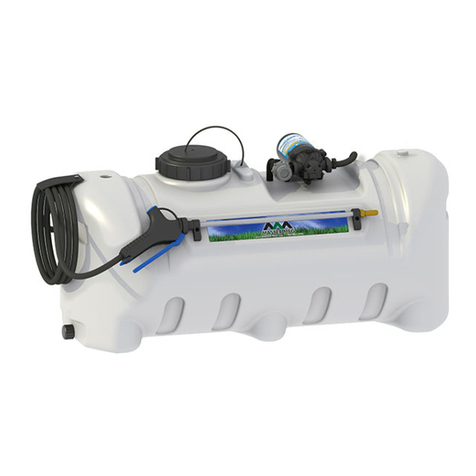
Master MFG S3O-61-060D-MM User manual

S3O-61-060D-MM | Revision 1 Jan. 2020
MASTER MFG
60 GALLON
DELUXE 3-POINT SPRAYER

CONTENTS
Introduction
Page 3
Warranty Parts Service
Page 3
Assembly
Page 4
Wiring Harness
Page 7
Operation
Page 8
Calibration
Page 9
Cleaning & Storage
Page 10
Troubleshooting
Page 11
Parts Breakdown
Page 12

INTRODUCTION
Your Master Manufacturing Deluxe 3-Point Sprayer has been manufactured to provide years of dependable and
efficient use. Proper operation and maintenance will ensure long satisfactory service. The purpose of this
manual is to assist you in the assembly, operation and maintenance of your sprayer or accessories. Please read
through this manual completely to fully understand how to operate and maintain your equipment. Keep your
manual in a safe, convenient place for future reference. Always mention the model and part number in any
correspondence.
Do not allow anyone to operate or maintain this equipment who has not fully read and
comprehended this manual. Failure to follow the recommended procedures may result in personal injury or
death or equipment damage.
Information in this manual is designed to help owners and operators to obtain the best results and safe operation
from their investment. The life of any machine depends largely on the care it is given and we suggest that the
manual should be read and understood and referred to frequently. If for any reason you do not understand the
instructions and safety requirements, please contact your authorized dealer. The intent of this manual is to
provide guidelines to cover general use and to assist in avoiding accidents and injuries.
There may be times when circumstances occur that are not covered in the manual. At those times it is best to
use common sense and contact your authorized dealer or our factory.
The requirements of safety cannot be emphasized enough in this publication. We urge you to make safety your
top priority when using and maintaining the equipment. We strongly advise that anyone allowed to operate this
equipment be thoroughly trained and tested, to prove they understand the fundamentals of safe operation.
WARRANTY PARTS SERVICE
Products sold shall be warranted from defects in workmanship and material when used within the service and
scope for which they were designed for a period of one year from date of purchase.
Warranty covers replacement parts ONLY. Please have your original sales receipt or other proof of purchase
date when requesting any warranty parts. To ensure the correct parts are acquired always provide the model
number of your sprayer/attachment and the part number and description obtained from the illustrated parts
breakdown in this manual.
Warranty is void if the use of chemicals that are corrosive or harmful to the internals of the pump are used. It is
the user’s responsibility to make sure the chemical used is compatible with Viton, Santoprene and
Polypropylene. If the chemical is not found to be compatible the warranty is void. Approved liquids include
non-flammable liquids, pesticides, water for plants and dust control, ice control chemicals, and water-based
non-flammable sealants or stains for outdoor wood surfaces. Please contact Customer Service at 320-340-6464
if you have questions regarding the liquids you would like to use.

ASSEMBLY
Tools Required: Philips Head Screwdriver, Pliers and Socket Wrench.
Most of the assembly has been completed during the manufacturing process. Only a few short steps are
required to complete your sprayer. Open the shipping carton and remove the contents. Follow the steps below
to assemble your 3-point sprayer:
Step 1) Locate screw holes on front of Sprayer Tank. With
Screws, install Gun Clips to the front of Sprayer Tank. Be
sure open end is facing top of the sprayer.
Step 2) Seat Drain Cap Gasket into Drain Cap. Attach Drain
Cap Tether to Top of Drain Cap. Place other end of Drain Cap
Tether over Drain Port. Thread Drain Cap onto Drain Port.
Step 3) Un-thread Tank Lid from Sprayer Tank. Insert
Tank Lid Tether from bottom of Tank Lid, “T” end
first. Pull Tank Lid Tether through top Tank Lid, so ball
end remains inside the Tank Lid. Thread Tank Lid back
on Sprayer Tank. Thread “T” end of Tether through
hole next to Tank opening.

Step 4) Wrap a small amount of Teflon tape around the
threads of the Pressure Gauge. Thread Pressure Gauge into
the top of the Pressure Regulator Assembly. Take care not
to cross-thread the Pressure Gauge. Note: Pressure Gauge
should be facing forward with Regulator Assembly knob.
Step 5) Slip the ½” Hose Clamp over the end of the
Spray Gun Hose. Push Spray Gun Hose onto the bottom
hose barb of the Pressure Regulator Assembly. Tighten
the Hose Clamp with Pliers.
Step 6) Place Fan Tip into Fan Nozzle Cap. Insert
Gasket into Fan Nozzle Cap. Then Place Nozzle Strainer
into Nozzle Assembly Port. Press Fan Nozzle Cap onto
Nozzle Assembly Port. Twist to Lock.
Repeat this step for the other remaining Nozzle
Assembly Ports.

Step 6) Place 1” Bolts through Boom Assembly and into
the Boom Brackets on the rear of the frame. Secure with
Flange Nuts and tighten with a Socket Wrench.
Step 7) Locate Boom Hose and make sure there is a
Washer in the end of Boom Cap. Thread the Boom Hose
to the Shut-Off Valve. Note: Use a knife to cut zip tie
from Boom Assembly to free the Boom Hose.

WIRING HARNESS
Before spraying chemicals, fill the tank half full of plain water to allow familiarization
with the sprayer and to prevent waste of expensive chemicals.
Operating power is obtained
directly from a 12 VDC
source. Be sure to connect
the red to the positive (+)
source and attach the black
to the negative (-) source.
IMPORTANT

OPERATION
!! IMPORTANT !! –It’s important to test the sprayer with plain water after assembly and any extended
period of storage. This will allow you to check for leaks without wasting expensive chemical or damaging
an area that you’re trying to spray.
Attach the sprayer to a tractor, then fill the tank approximately ½ full with water and connect the wiring harness
to a 12VDC source.
Ensure the boom valve is in the closed position, then turn the wiring harness switch to the ON position. The
pump should run for a short period of time until the pump is primed then automatically turn off. KEEP THE
SWITCH ON TO PERFROM THE FOLLOWING TESTS. Check for any leaks and make repairs if necessary.
Using the spray wand, ensure the nozzle is pointed down and away from yourself or others, then cycle the
trigger on the spray gun a few times until water sprays out from the nozzle consistently. Release the trigger and
confirm the pump comes up to pressure and stops. Locate the spray boom valve and turn the valve to the open
position. Confirm the booms spray pattern is facing down and even from side to side. Adjust nozzle position as
necessary. Turn off the spray boom valve. Once again, the pump should come up to pressure and shut off.
Check the entire system for leaks and make any necessary adjustments. Turn the power switch to the off
position.
Your sprayer is equipped with an inline switch located in the wiring harness. This switch is used to operate the
pump on or off.
There is also a secondary switch located in the pump. This switch is designed to turn the pump off when it
reaches 40 psi. This switch is calibrated at the factory and should not be tampered with.
Ensure the basket strainer is in place and fill the tank with the desired amount of water based on the amount of
solution needed. Measure out the chemical required for the amount of fresh water in the tank as specified by the
chemical label. Slowly pour the chemical into the tank while mixing. Initially you can remove the basket
strainer and use the spray gun to spray back into the tank to help the mixing process and purge mixed solution
through the pump and spray wand hose. Make sure you replace the basket strainer when done.
Using the handgun
-Ensure the power switch is in the on position.
-Begin spraying by pointing the spray nozzle toward the ground and squeezing the handle lever. The
pump will turn on automatically.
-The spray pattern exiting the nozzle can be adjusted from a straight stream to a cone pattern by rotating
the nozzle.
Using the spray boom
-Ensure the power switch is in the off position.
-Pull the sprayer to the location you would like to spray and turn the boom valve to the on position.
-Begin pulling the sprayer at the desired MPH (See calibration section) and turn the power switch to the
on position. The pump will start to run and the boom will begin spraying.
-Use the power switch to cycle the pump between spraying and stopping.
-When spraying in rows it is common practice to overlap your spray pattern by 50% to ensure
consistent chemical delivery.

CALIBRATION
Fan Spray Nozzles: The Fan Spray Nozzles on the boom will spray an 156” swath. The nozzle height should
be approximaetly 15” above the objext being sprayed.
GALLONS PER ACRE, 20” SPACING
Nozzle
PSI
GPM
4 MPH
5 MPH
6 MPH
7 MPH
8 MPH
9 MPH
10 MPH
90.080.015
Orange
30
0.17
12.6
10.1
8.4
7.2
6.3
5.6
5.0
40
0.20
14.9
11.9
9.9
8.5
7.4
6.6
5.9
50
0.22
16.3
13.1
10.9
9.3
8.2
7.3
6.5
60
0.24
17.8
14.3
11.9
10.2
8.9
7.9
7.1
75
0.27
20.0
16.1
13.4
11.5
10.0
8.9
8.0
Once you know how much you are going to spray, determine (from the top chart) the spraying pressure(PSI)
and the spraying speed (MPH)
When selecting pressure from the top chart, it is a good idea to try for the 30 PSI range as this allows and
excellent nozzle pattern. At 10 PSI the pattern begins to break up and at 40 PSI you may notice some drift.
Conditions of weather and terrain must be considered when setting the sprayer. Do not spray on windy days.
Protective clothing must be worn in some cases. Be sure to read the cehmical label carefully.
After all calibrations have been completed, add water and chemical to the tank. Always follow chemical
manufacturer’s instrautions for mixing. Conditions of weather and terrain must be considered when setting the
sprayer. Do not spray on windy days. Protective clothing must be worn in some cases. Be sure to read the
cehmical label carefully.

CLEANING & STORAGE
Spray materials can be highly toxic. Make sure to read and follow all warning labels.
Most spray materials are highly corrosive. The most important aspect of long, dependable
service from the sprayer is a thorough cleaning immediately following each use. In addition, the residue of one
type of chemical could cause an undesirable effect when a different chemical is used for a different purpose.
The most effective cleaning method is to pump several rinses of clean water through the tank, pump, hoses,
boom, spray gun, etc. A neutralizing agent such as a solution of Nutra-Sol, a detergent or household ammonia,
as recommended by the chemical manufacturer, can assist in removal of a persistent chemical. When the
system is thoroughly cleaned, drain the tank, suction line, pump, hoses, etc.
The following steps should be followed for the maintenance and storage of your sprayer.
1. Wash and flush out sprayer after completion of each phase of your program. Flush out sprayer when
changing chemicals if there is a possibility of the chemicals being incompatible. Use of a detergent
is advisable if the chemical manufacturer does not make specific cleaning recommendations.
Flush system completely, including nozzles. Never use metal objects to open clogged nozzles.
2. Clean sprayer thoroughly before storing at the end of the spraying season. Permanent type anti-
freeze added to the final rinse will leave a rust inhibiting film in parts of the sprayer.

TROUBLESHOOTING
Pump Will Not Turn On
Check For Loose Wiring
Make Sure Switch Is Turned On
Check The Fuse
Check For Defective Pressure Switch
Tap On Motor To Ensure Brushes Not Stuck
Low Pressure/Low Flow
Check If Inlet Hose/Filter To Pump Is Clogged
Check For Proper Battery Voltage To Pump
Flush Pump w/ Garden Hose Up To Strainer
Pump Cycles
Adjust Spray Wand Tip To See If There Is Back Pressure From
Too Fine of a Mist
Boom Nozzle/Filter Clogged
Check If Filter In Handle Is Clogged
Fuse Is Blown
Excess Voltage
Damaged or Defective Wiring Harness
Defective Pump Motor
Pump Continually Cycles On/Off Creating Too Much Amp
Draw
Pump Leaks
Check For Loose Fasteners & Tighten
Check Pump Seals Degraded. Replace If Needed
Leak In Diaphragm. Replace Diaphragm Assembly
Poor Spray Distribution
Check Suction Strainer & Clean If Necessary
Clogged Intake Tube. Clean If Needed
Worn Spray Gun Nozzle. Replace Spray Gun
Pump Cycles While
Spraying
Check For Leak In System. Tighten Clamps, Fittings or Replace
Spray Gun
Pressure Switch Might Be Faulty. Replace
Check Voltage To Determine If Low
Air Might Be Trapped In System, Purge Air

PARTS BREAKDOWN

PARTS BREAKDOWN

PARTS BREAKDOWN
Table of contents
Other Master MFG Paint Sprayer manuals

Master MFG
Master MFG MASTER GARDNER PCD‐E3‐009B‐MM User manual

Master MFG
Master MFG 12 VOLT SPOT SPRAYER Installation instructions

Master MFG
Master MFG 300 Gallon Space Saver User manual

Master MFG
Master MFG New Direction User manual

Master MFG
Master MFG SSBK-240 User manual

Master MFG
Master MFG Revolt Installation instructions

Master MFG
Master MFG SAO-H3-015B-MM User manual

Master MFG
Master MFG 90700008 User manual

Master MFG
Master MFG PCD-E3-009B-MM MASTER GARDNER User manual