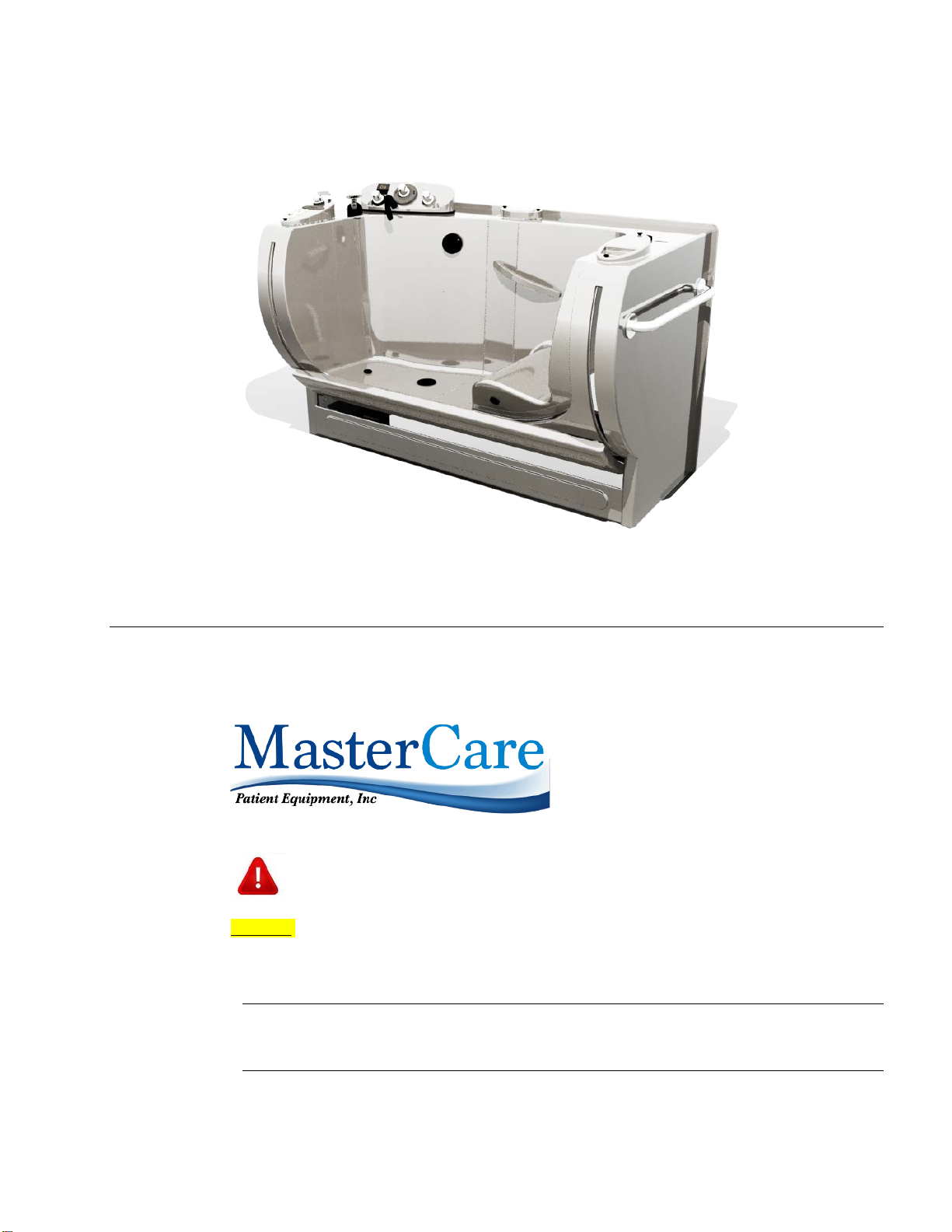
Generation II Entree Bath –All Models
INSTALLATION MANUAL
2071 14th Ave – Columbus, NE 68601
800-798-5867 FAX: 402-563-9102
INSTALLATION CHECK LIST
1. Upon Receipt:
Immediately upon receipt, check for visible freight damage. If damage is found, it must be reported,
communicated and documented immediately to the freight company and MasterCare 1-800-798-5867. Proceed to
inspect the tub for hidden and concealed damage. Leave the tub on the pallet until ready for installation. If the tub
is going to be stored for a period of time before installation, cover it with a tarp to protect it from dust and
construction debris.
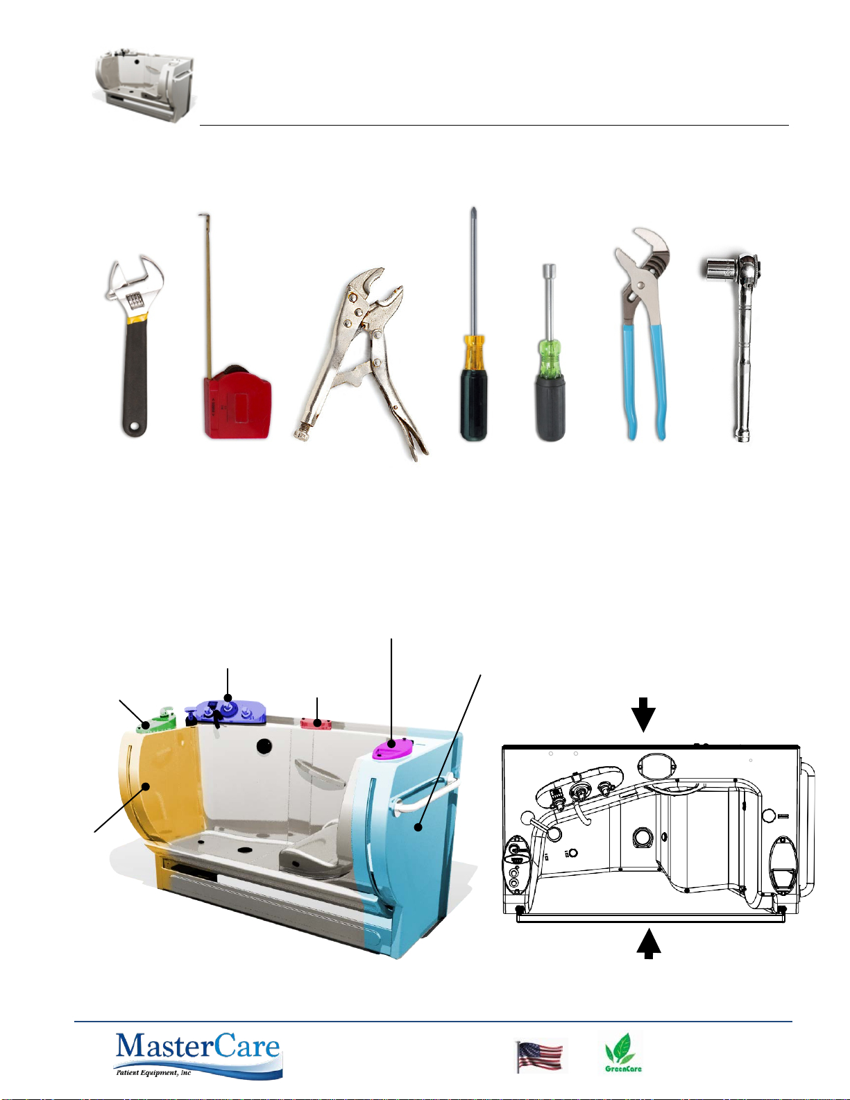
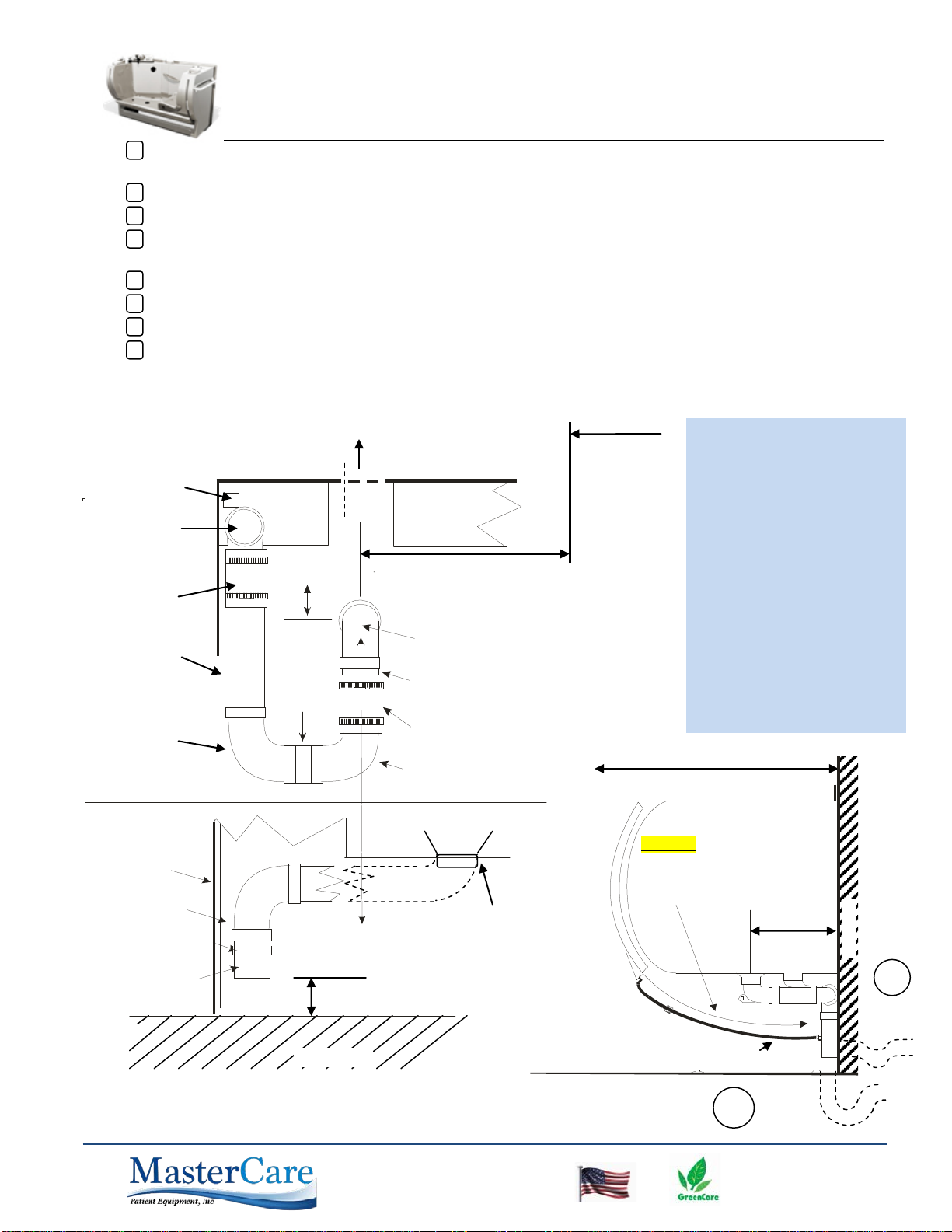
2. Entree Bath Uncrating Instructions: (Note: Read and follow instructions thoroughly.
Refer to the drawing on following page to reference details.)
a. Remove the stretch wrap (plastic) from the outside of the crate.
b. Remove the ten (10) lag screws from the bottom of the crate (Detail 1).
c. Two people will now be required to lift the crate over the top of the Entree
Bath.
d. Set aside the
Entree Gen II Starter Kit box and the Combo Case
from the
pallet. It is recommended to leave the stretch wrap (plastic) on the Entree
Bath until the tub is in its final location.
e. Remove the two (2) 10-32 x ¾” thumbscrews from the Entree cover panel
(Detail 4). Gently remove the cover panel from the tub.
CAUTION: Remove the cover panel before removing the tub from the crate.
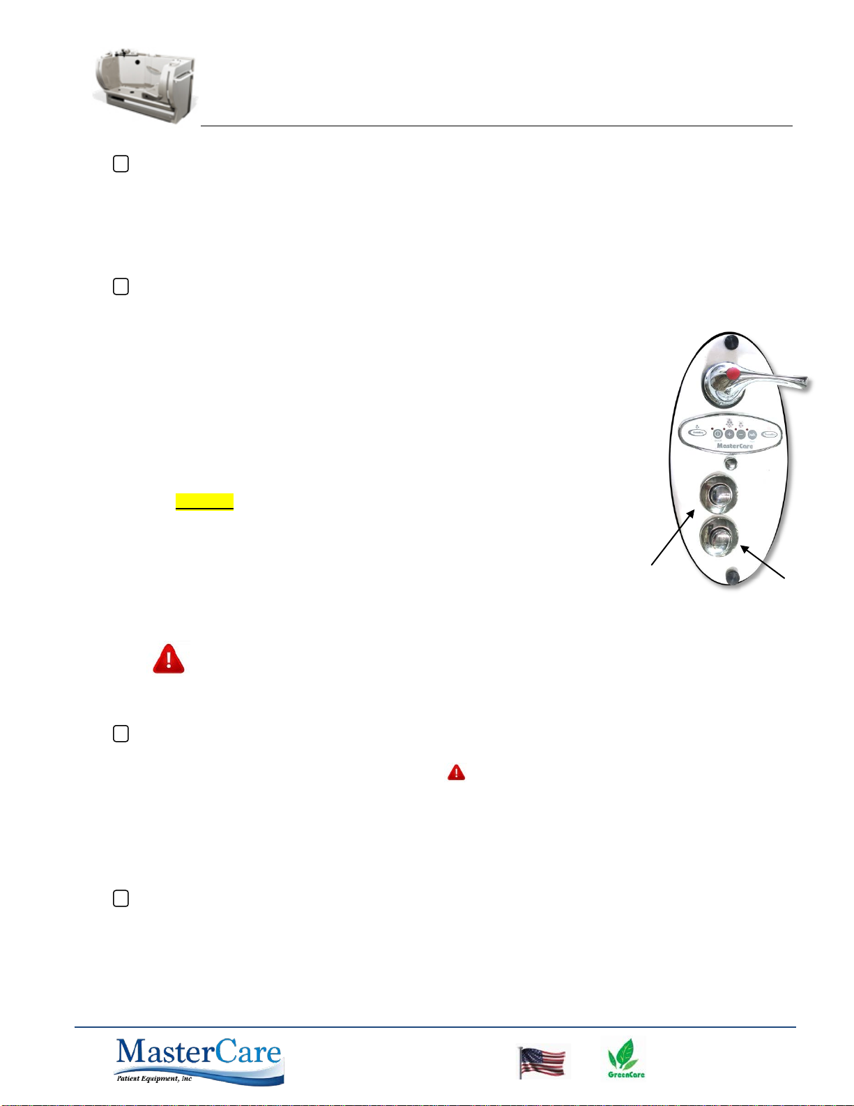
f. Locate the Tub Power Cord, center rear back of tub, then plug in the tub and
close the door halfway by depressing the Door Close button located on the
Foot End Control Panel. Locate the two lag screws by looking through the
service hole located on the backside of the tub (Detail 3). Proceed to
remove the two lag screws; discarding board.
g. Remove the four (4) screws from each of the anchoring plates (Detail 2).
h. The Entree Bath can now be lifted off of the pallet.
The Entree Bath is VERY HEAVY. Two people (Minimum) are required to move the Entree Bath.
i. Position the cover panel onto the front of the Entree Bath and line up the screw holes (Detail 4). Place one
of the 10-32 x ¾” thumbscrews into each hole on the cover panel and tighten accordingly.
3. Transfer and Positioning: The tub is shipped with the door in the open position. To transfer, plug the tub into
an
extension cord and rotate the door to a nearly closed position, by pushing on the Door Close button until the door
rotates all the way up and it just starts to cam in. Do not close the door all the way so that the seal is
compressed. Leaving the door closed with the seal compressed over a long period of time can damage the seal.
The tub may have to be in an open position to get through some doors. After the tub is on-site, leave the special
packing around the
tub door on until after the tub is installed and ready for its test operation. Check again to make
sure the door is not
fully closed and compressing the seal.
4. Connect the electrical service to the tub. The tub comes with a cord with a plug, or it can be hard wired with flex
watertight conduit by an electrician. (Verify that the tub is properly grounded if rewired).
button
button


 owner's manual")