MasterForce 207-1508 User manual

6 Gallon Air Compressor
207-1508
To Reduce The Risk Of Injury, User Must Read And
Understand Operator’s Manual. Save These Instructions For Future Reference.
OPERATOR’S MANUAL
CAUTION:

TABLE OF CONTENTS
Safety Symbols .............................................................................................................................
Safety Instructions ........................................................................................................................
Overview / Specifications ..............................................................................................................
Assembly Instructions ...................................................................................................................
Important Information ...................................................................................................................
Operating Instructions ..................................................................................................................
Maintenance .................................................................................................................................
Troubleshooting ............................................................................................................................
Exploded View ..............................................................................................................................
Parts List .......................................................................................................................................
Page 3
Table Of Contents........................................................................................................................ Page 2
Page 4-6
Page 7
Page 10
Page 9
Tool Compatibility Chart ............................................................................................................... Page 8
Page 11-12
Page 13
Page 14-15
Page 16
Page 17
NOTES
......................................................................................................................................... Page 18
Page 3Page 2
SAFETY SYMBOLS
This Symbol Designates That This Tool Is Listed By Underwriters
Laboratories, To United States And Canadian Standards
This Symbol Designates That This Tool Is Listed By The Canadian
Standards Association, To United States And Canadian Standards
This Symbol Dsignates That This Tool Is Listed By The Intertek
Testing Services, To United States And Canadian Standards
This Symbol Designates That This Tool Is
Listed By Underwriters Laboratories
This Symbol Designates That This Tool Is Listed
By The Canadian Standards Association
A
Hz
W
~
n0
lbs
.../min
Symbol
Amperes
Hertz
Watts
Alternating current
Direct current
No-load speed
Pounds
Per minute
Class II construction
Read the operator’s
Manual
Wear safety glasses
Wear hearing
Protection
Warning symbol
Name
V Volts Voltage
Current
Frequency (cycles per second)
Power
Type of current
Type or characteristic of current
Rotational speed, at no load
Weight
Revolutions, strokes, surface speed orbits,
etc. Per minute
Double-insulated construction
To reduce the risk of injury, read
and understand operator’s manual
Operation of power tool can result in
foreign objects being thrown into eyes
Wear respiratory
Protection
Use of this tool can generate dust
which may cause respiratory injury
Noise from this product
can contribute to hearing loss
Wear gloves Wear gloves to reduce risk of injury
Alerts user to warning messages
Designation / Explanation
Some of the following symbols may be used on your tool. Please study them and learn
their meaning. Proper interpretation of these symbols will allow you to operate the tool
better and safer.

SAFETY INSTRUCTIONS
The purpose of safety symbols is to attract your attention to possible dangers. The safety
symbols, and the explanations with them, deserve your careful attention and understanding.
The symbol warnings do not by themselves eliminate any danger. The instructions and
warnings they give are no substitutes for propper accident prevention measures.
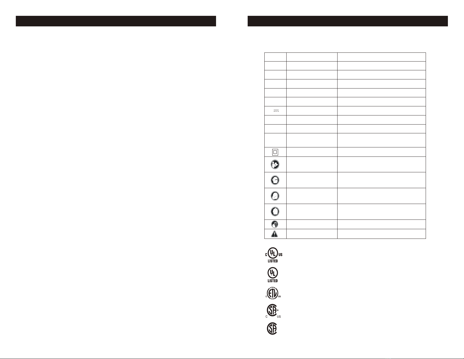
SAFETY ALERT SYMBOL:
Indicates DANGER, WARNING, OR CAUTION.
May be used in conjunction with other symbols or pictographs
Be sure to read and understand all safety insructions in this
manual, including all safety alert symbols such as “DANGER”, “WARNING” and
“CAUTION”, before using this power tool. Failure to follow all instructions listed
below may result in electric shock, fire and/or serious personal injury.
SYMBOL MEANING
Failure to obey this safety warning CAN result in death or
serious injury to yourself or to others. Always follow the safety precautions to
reduce the risk of fire, electric shock and personal injury.
WARNING:
Failure to obey this safety warning MAY result in personal
injury to yourself or others or property damage. Always follow the safety
precautions to reduce the risk of fire, electric shock and personal injury.
CAUTION:
Failure to obey this warning WILL result in death or serious
injury to yourself or to others. Always follow the safety precautions to reduce the
risk of fire, electric shock and personal injury.
DANGER:
WARNING:
WORK AREA SAFETY
1. Keep your work area clean and well lit.
Cluttered workbenches and dark areas invite
accidents.
2. Do not operate power tools in explosive
atmospheres, such as in the presence of
flammable liquids, gases, or dust. Power tools
create sparks which may ignite the dust or
fumes.
3. Keep bystanders, children and visitors
away while operating a power tool.
Distractions can cause you to lose control.
4. Make your workshop childproof with padlocks
and master switches. Lock tools away when not
in use.
5. Make sure the work area has ample lighting
so you can see the work and that there are no
obstructions that will interfere with safe
operation before using your power tool.
PERSONAL SAFETY
SAFETY INSTRUCTIONS
1. Know your power tool. Read the operator’s
manual carefully. Learn the power tools
applications and limitations, as well as the
specific potential hazards related to this tool.
2. Stay alert, watch what you are doing and
use common sense when operating a power
tool.
3. Do not use tool while tired or under the
influence of drugs, alcohol or medication. A
moment of inattention while operating power
tools may result in serious personal injury.
4. Dress properly. Do not wear loose clothing
or jewelry. Pull back long hair. Keep your hair,
clothing, and gloves away from moving parts.
Air vents often cover moving parts and should
also be avoided. Loose clothing, jewelry or
long hair can be caught in moving parts.
5. Avoid accidental starting. Be sure switch is
in “OFF” position before plugging in. Do not
carry tools with your finger on the switch.
Carrying tools with your finger on the switch or
plugging in tools that have the switch in the
“ON” position invites accidents.
6. Remove adjusting keys or wrenches
before turning the tool “ON”. A wrench that is
left attached to a rotating part of the tool may
result in personal injury.
7. Do no overreach. Keep proper footing
and balance at all times. Proper footing and
balance enables better control of the tool in
unexpected situations.
8. Always secure your work. Use clamps or a
vise to hold work when practical. It is safer
than using your hand and frees both hands to
operate tool.
9. Use safety equipment. Always wear eye
protection. Dust mask, non-skid safety shoes,
hard hat or hearing protection must be used
for appropriate conditions.
10. Do not use on a ladder or unstable
support. Stable footing on a solid surface
enables better control of the tool in
unexpected situations.
TOOL USE AND CARE SAFETY
1. Always use clamps or other practical ways
to secure and support the work piece to a
stable platform. Holding the work by hand or
against your body is unstable and may lead to
loss of control.
2. Do not force the tool. Use the correct tool
and blade for your application. The correct tool
and blade will do the job better and safer at
the rate for which it is designed.
3. Do not use the tool if switch does not turn
it “ON” or “OFF”. Any tool that cannot be
controlled with the switch is dangerous and
must be repaired.
4. Disconnect the plug from the power source
before making any adjustments, changing
accessories or storing the tool. Such
preventive safety measures reduce the risk of
starting the tool accidentally.
5. Never leave the tool running. Always turn it
off. Do not leave the tool until it comes to a
complete stop.
6. Store idle tools out of the reach of children
and other untrained persons. Tools are
dangerous in the hands of untrained users.
7. Maintain tools with care. Keep cutting tools
sharp and clean. Properly maintained tools
with sharp cutting edges are less likely to bind
and are easier to control.
8. Check for misalignment or binding of
moving parts, breakage of parts, and any
other condition that may affect the tool’s
operation. If damaged, have the tool serviced
WARNING:
BE SURE to read
and understand all instruction before
operating this power tool. Failure to follow
all instructions listed below may result in
electric shock, fire and/or serious
personal injury.
Page 5Page 4
This product can expose you to chemicals including lead
which is known to the State of California to cause cancer and birth defects or
other reproductive harm.Wash hands after handling. For more information go
to www.P65Warnings.ca.gov/products.
WARNING:

OVERVIEW
SPECIFICATIONS
SAFETY INSTRUCTIONS
EXTENSION CORDS
WARNING:
Check extension cords
before each use. If damaged, replace
immediately. Never use tool with a
damaged cord since touching the
damaged area could cause electrical
shock, resulting in serious injury.
CAUTION:
Keep the extension
cord clear of the working area. Position the
cord so that it will not get caught on
lumber, tools or other obstructions while
you are working with a power tool.
MINIMUM GAUGE FOR EXTENSION CORDS
Ampere Rating
Total Length Of Cord
(When using 120 volts only)
More Than< >Less Than 25ft. 50ft. 100ft. 150ft.
0 6 18 16 16 14
6 10 18 16 14 12
10 12 16 16 14 12
12 16 14 12
Not
Recommended
before using. Many accidents are caused by
poorly maintained tools.
9. Use only accessories that are recommended
for this tool. Accessories that may be suitable
for one tool may become hazardous when used
on another tool.
Use a proper extension cord. Only use cords
listed by Underwriters Laboratories (UL).
Other extension cords can cause a drop in
line voltage, resulting in a loss of power and
overheating of tool. When operating a power
tool outdoors, use an outdoor extension cord
marked “W-A” or “W”. These cords are rated
for outdoor use and reduce the risk of electric
shock.
Page 7Page 6
Item#:
Motor: 120V~, 60Hz, Universal
Running Horsepower: 1.5 HP
Amperes: 13 A
Tank Size: 6.0 U.S. gallons
Air Delivery (CFM*)@40 PSI: 4.0
Air Delivery (CFM*)@90 PSI: 3.0
Cut-in Pressure(PSI): 145
Cut-out Pressure(PSI): 175
Pump Design: Oil-free, Direct Drive
Power Cord: SJ 16AWG × 12 ft
Weight:
ELECTRICAL SAFETY
Handle
Motor & Pump
Tank Drain
Power Switch
Regulator
Safety Valve (Not Visible)
Tank
Quick Couplers
Tool Gauge
1. Avoid body contact with grounded surfaces
such as pipes,radiators, ranges, and
refrigerators. There is an increased risk of
electric shock if your body is grounded.
2. Do not expose power tools to rain or wet
conditions. Water entering a power tool will
increase the risk of electric shock.
3. Do not abuse the cord. Never use the cord
to carry the tool or pull the plug from an outlet.
Keep the cord away from heat, oil, sharp
edges, and moving parts.
4. Replace damaged cords immediately.
Damaged cords increase the risk of electric
shock.
Grounded
outlet
Grounding Pin
Plug
207-1508
This compressor should be used on a
nominal 120V grounded circuit. Use a power
cord that is equipped with a grounding plug.
Verify that the compressor is plugged into an
outlet that has the same configuration as the
plug. Do not use an adaptor with this
compressor.
Note
Tank Gauge
29.3 lbs

Tool Compatibility Chart
SAVE THESE INSTRUCTIONS
This manual contains important safety and operating instructions.
Read all instructions and follow them with use of this product.
Always ensure the use of appropriately matched air tools with your air compressor. Be
sure that the air compressor being used can supply the appropriate volume, pressure and
delivery rate of air to the tool(s) without running continuously. Using tools or combinations
of tools that, together or separately, require more than the air compressor can deliver will
void the air compressor guarantee/warranty.
Compatible compressor and air tool - proper usage and operation
Important Information
Page 9Page 8
PRODUCT FE
207-1508
ATURES
Electric Motor
The motor is used to power the pump. It is equipped with a thermal overload protector.
If the motor overheats for any reason, the thermal overload protector will shut it down in
order to prevent the motor from being damaged.
Air Compressor Pump
The pump compresses the air and discharges it into the tank via the piston that moves up
and down in the cylinder.
Safety Valve
This valve is used to prevent the compressor from building too much pressure. If the
pressure reaches the preset level of the motor, it will automatically pop open. You can also
pull the ring on the valve to open manually.
Power Switch
This switch turns the compressor on and off manually. ALWAYS set this switch to the OFF
position when the compressor is not being used and before unplugging.
Air Pressure Regulator
The regulator is used to adjust the pressure inside the line to the tool that is being used.
Turn the knob clockwise to increase the pressure and counter-clockwise to decrease the
pressure.
Tank Pressure Gauge
The gauge measures the pressure level of the air that is stored in the tank. It cannot be
adjusted by the operator and it does not indicate the pressure inside the line.
Tool Pressure Gauge
The gauge measures the regulated outlet pressure.
Air Outlet (Universal Coupler)
The outlet is connected to the 1/4” (6.4 mm) NPT air hose.
Tank Drain
The tank drain is used to remove moisture from the air tank after the compressor is shut off.
Air Tank
The tank is where the compressed air is stored.
Power Cord
This compressor should be used on a nominal 120V grounded circuit. Use a power cord
that is equipped with a grounding plug. Verify that the compressor is plugged into an
outlet that has the same configuration as the plug. Do not use an adaptor with this
compressor.
This air compressor is ideal for a wide range of jobsite applications. The 6 gallon design
provides optimum pressure. It features a 1.5 HP universal motor and oil-free pump.
The procedures described in this manual are solely for this 6 gallon air compressor
at a maximum pressure of 175 PSI.

Packaging Contents:
DESCRIPTION
Air compressor
Owner’s manual
QTY ILLUSTRATION
Positioning of the air compressor
1
1
231
Assembly Instructions
2
3
FIG. A
FIG. B
1. Position the air compressor (1) near an
electrical outlet (2)(FIG. A).
2. The compressor must be at least
12”(31cm) from any wall (3) or abstruction,
in a clean, well-ventilated area to ensure
sufficient air flow and cooling(FIG. A).
3. Place the air compressor on the floor or
a hard, level surface.
4. Connect the air hose (1) to the
compressor’s air outlet (universal coupler) (2)
with the universal quick plug (3) (FIG. B).
Note: Attach air hose and accessories
(not provided). Apply plumber’s tape on
all the threads to prevent air leakage.
Unpack the air compressor unit. Inspect the unit for damage. If the unit has been damaged,
contact the retailer immediately.
Check the air compressor’s identification label to ensure that you have purchased the
intended model and that it has the required pressure rating for its intended use.
Operating Instructions
1. Set the power switch to the OFF
position (Fig. D).
FIG. C
2. Turn the air pressure regulator knob
counter-clockwise until it stops(Fig. E).
3. Attach hose and accessories (FIG. F).
FIG. F
Hot compressor
surfaces could result in serious injury.
Allow compressor to cool before
touching.
High pressure air
could result in death or serious injury.
Never operate above maximum
operating pressure of the spray
gun or tool.
WARNING:
WARNING:
Notice
If the pump has been transported or
turned upside down (even partially),
allow the pump to sit in a normal,
Check Safety Valve
Before starting compressor, pull the
ring on the safety valve to make sure
that the safety valve operates freely.
If the valve is stuck or does not
operate smoothly, contact a trained
service technician(Fig. C).
Page 11Page 10
FIG. E
upright position (FIG. A) for
approximately 10 minutes before starting.
FIG. D
OFF
1

High pressure air could
result in death or serious injury. Shut off unit,
unplug and release air pressure prior to
servicing.
High pressure air
containning water condensation could
result in minor or moderate injury. Do
not spray at any person.
Risk of serious eye injury
from moisture and debris. Always wear ANSI
Z87.1 safety goggles when opening tank drain.
Operating Instructions
WARNING:
WARNING:
CAUTION:
5. Set the power switch to the ON position
and allow the tank pressure to build. Motor
will stop when tank pressure reaches cut-out
pressure(Fig H).
Shut down
1. Set the power switch (1) to the OFF
position.
2. Unplug the power cord (2).
3. Reduce the pressure in the tank through
the outlet hose. Pulling the safety valve ring
(3) and keeping it open will also reduce the
pressure in the tank(fig. I).
4.Set tank drain (4) (fig. I) to OFF to
ensure tank is drained.
1
3
4
2
FIG. I
Drain the tank
1. Set the power switch to the O (OFF)
position.
2. Turn air pressure regulator knob
counter-clockwise to set the outlet pressure
to zero.
3. Pull and hold ring on safety valve, allowing
air to bleed from the tank until air pressure is
minimized.
4. Place a suitable container under the unit to
catch any water.
5. Slightly tilt unit and turn tank drain counter-
clockwise to open.
6. After the water has been drained,close
the tank drain (clockwise). The air compressor
can now be stored.
4. Close the tank drain (1) . Plug-in
the power cord(2) (FIG. G).
2
1
OFF
ON
FIG. G
Page 13Page 12
Check that all connections are tight. Small leaks in the tank,
hoses,connections or transfer tubes will substantially reduce the
air compressor and tool performance. Spray a small amount of
soapy water around the area of suspected leaks with a spray
bottle. If bubbles appear, repair: replace or reseal the faulty
component. Do not over-tighten any connections.
Before storing the air compressor compressor:
Drain tank (page 12).
Use an air blow gun to clean all dust and debris from the
pressor.
Disconnect and wind up the power cord.
Clean the ventilation openings on the motor enclosure with
a damp cloth.
Drain all moisture from the tank.
Pull the pressure safety valve to release all pressure from the
tank.
Cover the entire unit to protect it from moisture and dust.
Store the air compressor in a clean and dry location.
In cold weather, store the compressor in a warm building when
it is not in use. This will reduce problems related to starting the
motor and the freezing of water condensation.
Pull/actiate the safety valve daily to ensure that it is operating
properly and to clear the valve of any possible obstructions.
DESCRIPTION / REASON SERVICE
INTERVAL
ITEM
Through normal operation of your air compressor,
conndensation water will accumulate in the tank. To prevent
corrosion of the tank from the inside, condensation must be
drained at the end of every workday. Be sure to wear protective
goggles. Relieve the air pressure in the system then open the
tank drain on the bottom of the tank to drain. Under cold
conditions it is especially important to drain the tank after each
use to reduce the chance of problems resulting from the freezing
of condensation water.
NOTE: Refer to instructions on how to drain tank (page 12).
Drain the
tank
Check the
valve
Test for
leaks
Storage
Daily
Daily
Monthly
Prior to
storing
Maintenance
FIG. H
OFF

Troubleshooting
The power cord is not plugged in.
The motor’s thermal overload
protection has tripped.
POSSIBLE CAUSE
PROBLEM
The motor will
not run or start
Plug the power cord into a grounded outlet.
Set the power switch to the ON position.
The power switch is in the
O (OFF) position.
The extension cord is the wrong
wire gauge or is too long.
A fuse has blown or a circuit
breaker has been tripped.
The air tank pressure exceeds
the preset power switch limit.
The safety valve is stuck open.
Electrical connections are loose.
The motor, capacitor, or safety
valve is defective.
The motor runs
continuously
when the
power switch
is in the ON
position.
Check extension cord information (page 6)
for the proper wire gauge and cord length.
Turn the air compressor off, unplug the
power cord and wait until the motor has
cooled down. Plug in the power cord only
after the motor has cooled down, and wait
for at least 5 minutes to make sure the
thermal overload protector has recovered.
Replace the fuse or reset the circuit
breaker.
Verify that the fuse has the proper
amperage.
Check for low voltage conditions.
Disconnect any other electrical appliances
from the circuit or operate the compressor
on a dedicated circuit.
The motor will start automatically when the
tank pressure drops below the cut-in
pressure.
Clean or replace the safety valve.
Contact an authorized service center.
Set the power switch to the OFF
position. If the motor does not shut off,
unplug the air compressor. If the power
switch is defective, replace it.
Check the air requirements of the
accessory that is being used. If it is higher
than the CFM (Cubic Feet per Minute )and
pressure supplied by the compressor
(page 7), a larger capacity air compressor
is needed. Most accessories are rated at
25% of actual CFM while running
continuously.
The prower switch does not
shut off the motor when the air
compressor reaches the cut-out
pressure and the safety valve
activates.
The compressor’s capacity is
not enough.
The regulator
does not
regulate the
pressure.
The regulator or its internal parts
are dirty or damaged.
Replace the regulator.
SOLUTIONS
Troubleshooting
Prolonged excessive use of air.
POSSIBLE CAUSEPROBLEM
The pressure
is low or
there is not
enough air.
Close the tank drain.
Clean or replace the air filter element.
Check the fittings with soapy water. Tighten
or reseal leaking fittings (apply plumber’s
tape on threads). Do not over tighten.
SOLUTIONS
The tank drain is open.
There is a leak at one of the
fittings.
The air intake is restricted.
There is a hole in the air hose.
There is condensation in the air
tank caused by a high level of
atmospheric humidity or because
the air compressor has not been
running long enough.
The tank leaks.
The ventilation is inadequate.
Cooling surfaces are dirty.
There is
moisture in
the discharge
air.
Decrease the amount of air used.
Check the air hose and replace it if
necessary.
Replace the tank immediately. Do not
attempt to repair it.
Relocate the compressor to an area with
cool, dry and well-circulated air.
Clean all cooling surfaces on the pump
and the motor thoroughly.
Replace worn parts and reassemble using
new plumber's tape.
The
compressor
overheats.
Check for worn parts and replace them if
necessary.
Drain the air tank after each use. Drain the
air tank more often in humid weather and
use an air-line filter.
The valve is leaking.
Page 15Page 14

Exploded View
Page 17Page 16
Parts List
Item# Part No. Description
1
2
3
4
J2996980526
J7105350774
J0305340773
J0022520037
F5013701213
Q087A968001
J0801100033
JA265530414
J8335360733
X3040350035
J2983450040
J0809760032
D1015001206
J3262970629
J3262980630
J0813140645
J0780270167
Q0874298001
J1240440020
A0860261134
J2981200040
J0782410032
D3003000011
D3005000119
J0183000632
Q0874308001
AT3802.00.00.01
J0905070201
X3110590032
J2983410668
J0801810032
5
6
7
8
9
10
11
12
13
14
15
16
17
18
19
20
21
22
23
24
25
26
27
28
29
30
Quick Coupler
Manifold
Pressure Regulator
Safety Valve
Pressure Gauge
Pressure Gauge Cover
Bolt M5
Silencer
Transfer Tube
Rubber Pad
Washer
Bolt M8
Power Cord
Handle
Handle
Screw
Screw
Upper Shroud
Crimping Board
Motor/Pump Washer
Screw M5
Washer
Power Switch
Pressure Switch
Check Valve
Lower Shroud
Air Tank
Tank Drain
Rubber Foot
Washer
Qty
2
1
1
1
2
1
1
1
1
3
3
3
1
1
1
2
9
1
1
1
2
2
1
1
1
1
1
1
3
3
Bolt M10 3

NOTES
Page 18 Page 19
SAVE YOUR RECEIPTS
THIS WARRANTY IS VOID WITHOUT THEM
6 Gallon Air Compressor
WARRANTY
90-DAY MONEY BACK GUARANTEE:
This MASTERFORCE®brand power tool carries our 90-DAY Money Back
Guarantee. If you are not completely satisfied with your MASTERFORCE®brand
power tool for any reason within ninety (90) days from the date of purchase, return
the tool with your original receipt to any MENARDS®retail store, and we will provide
you a refund – no questions asked.
3-YEAR LIMITED WARRANTY:
This MASTERFORCE®brand power tool carries our famous No Hassle 3-Year
Limited Warranty to the original purchaser. If, during normal use, this
MASTERFORCE®power tool breaks or fails due to a defect in material or
workmanship within three (3) years from the date of original purchase, simply bring
this tool with the original sales receipt back to your nearest MENARDS®retail store.
At its discretion, MASTERFORCE®agrees to have the tool or any defective part(s)
repaired or replaced with the same or similar MASTERFORCE®product or part
free of charge, within the stated warranty period, when returned by the original
purchaser with original sales receipt. Not withstanding the foregoing, this limited
warranty does not cover any damage that has resulted from abuse or misuse of
the Merchandise. This warranty: (1) excludes expendable parts including but not
limited to blades, brushes, belts, bits, light bulbs, and/or batteries; (2) shall be void
if this tool is used for commercial and/or rental purposes; and (3) does not cover any
losses, injuries to persons/property or costs. This warranty does give you specific
legal rights and you may have other rights, which vary from state to state. Be
careful, tools are dangerous if improperly used or maintained. Seller’s employees
are not qualified to advise you on the use of this Merchandise. Any oral
representation(s) made will not be binding on seller or its employees. The rights
under this limited warranty are to the original purchaser of the Merchandise and
may not be transferred to any subsequent owner. This limited warranty is in lieu of all
warranties, expressed or implied including warranties or merchantability and fitness
for a particular purpose. Seller shall not be liable for any special, incidental, or
consequential damages. The sole exclusive remedy against the seller will be for the
replacement of any defects as provided herein, as long as the seller is willing or able
to replace this product or is willing to refund the purchase price as provided above.
For insurance purposes, seller is not allowed to demonstrate any of these power
tools for you.
For questions / comments, technical assistance or repair parts –
Please Call Toll Free:
1-888-899-0146
(M-F 8 am - 5 pm CT).

© 2021 Menard, Inc., Eau Claire, WI 54703 05/2021
Table of contents