OEM Tools 26100 User manual

Air Compressor
Manual
For questions concerning this air compressor,
please call 866-869-3114
Rev: 001 Part# 1312101633

TABLE OF CONTENTS
PAGE
1 Safety Guidelines - Denitions
Before Using the Air Compressor
2 When Installing or Moving the Compressor
Before Each Use
3 Follow Safety Precautions for Electrical Connection
Plan Ahead to Protect Your Eyes, Hands, Face & Ears
When Operating
4 Spraying Precautions
Perform These Maintenance Operations
5 Typical Compressor Installation
Glossary
6-9 Wiring
10-11 Starting the Compressor
12 QP Compressor
13-14 Troubleshooting
15 Pump and Tank Specs
16 Tank Warning
17 Parts Reference
18 Single Stage and Contractor
19 Two Stage
20 Gas Drive and Duplex
21 QP
22 Electric Two Stage and Duplex
23-24 PAT24 and PAT38
25 T29S
26 B5900
27 T39
28-29 C1
30-31 C2
Back Warranty Statement

UNPACKING
After unpacking unit, inspect carefully
for any damage that may have
occurred during transit. Check for
loose, missing, or damaged parts. If
any damage is observed, a shipping
damage claim must be filed with
carrier. Do not use the OEMTOOLS™
Compressor if broken, bent, cracked
or damaged parts (including labels) are
noted. Any Compressor that appears
damaged in any way, operates
abnormally or is missing parts should
be removed from service immediately.
If you suspect that the Compressor
was subjected to shock load (a
load that was dropped suddenly,
unexpectedly, etc.) immediately
discontinue use until it has been
checked by a factory authorized
service center.
Please read and save these instructions. Read through this owner’s manual carefully before using product. Protect yourself and
others by observing all safety information, warnings, and cautions. Failure to comply with instructions could result in personal
injury and/or damage to product or property. Please retain instructions for future reference.
The following safety information is provided as a guideline to help you operate your Compressor under the safest possible
conditions. Any tool or piece of equipment can be potentially dangerous to use when safety or safe handling instructions are
not known or not followed. The following safety instructions are to provide the user with the information necessary for safe
use and operation. Please read and retain these instructions for the continued safe use of your service system. Failure to
follow instructions listed below may result in serious injury. In addition, make certain that anyone who uses the equipment
understands and follows these safety instructions as well.
Operating Instructions and Parts Manual 26100, 26101, 26102, 26103, 26104, 26105 and 26106
FOR CUSTOMER SERVICE
Technical Question?
CALL 1-866-869-3114
AIR COMPRESSOR
WARNING: Pursuant to California Proposition 65, this product contains chemicals known to the state of California to cause
cancer and birth defects or other reproductive harm. Wash hands after handling.
Explanation of Safety Signal Words
DANGER: Means if safety information is not followed someone will be seriously injured or killed.
WARNING: Indicates a potentially hazardous situation which, if not avoided, could result in death or serious injury.
CAUTION: Indicates a potentially hazardous situation which, if not avoided, may result in minor or moderate injury.
CAUTION: Used without the safety alert symbol indicates a potentially hazardous situation which, if not avoided, may result
in property damage.
NOTES: Provide clarity and helpful information.
WARNING
3/17
2017 OEMTOOLS™1

2
Operating Instructions and Parts Manual 26100, 26101, 26102, 26103, 26104, 26105 and 26106
3/17
2017 OEMTOOLS™
AIR COMPRESSOR
IMPORTANT SAFETY INSTRUCTIONS
Save these instructions.
Improper operation or maintenance of this product
could result in serious injury and property damage.
Read and understand all warnings and operation
instructions before using this compressor.
1. Only persons familiar with these rules of safe
operation should use the air compressor.
2. Read the instruction manual carefully before
attempting to assemble, disassemble or operate
your system. Be thoroughly familiar with the
controls and the proper use of the equipment.
3. Review and understand all safety instructions and
operating procedures in this manual.
4. Review the maintenance methods for this compressor
(See “Maintaining Your Compressor” section).
5. Inspect your work area. Keep work area clean and
well lit.
6. Cluttered areas and benches invite accidents.
Floors must not be slippery from wax or dust.
7. Operate compressor in a well-ventilated area free
from flammable liquids and vapors.
8. Operate compressor in a ventilated area so that
compressor may be properly cooled and the
surrounding air temperature will not be more than
100°F.
9. Never use a compressor in a wet environment.
10.Protect material lines and air lines from damage or
puncture. Keep hose and wires away from sharp
objects, chemical spills, oil, solvents and wet floors.
11. A minimum clearance of 18 inches between the
compressor and a wall is required because objects
could obstruct airflow.
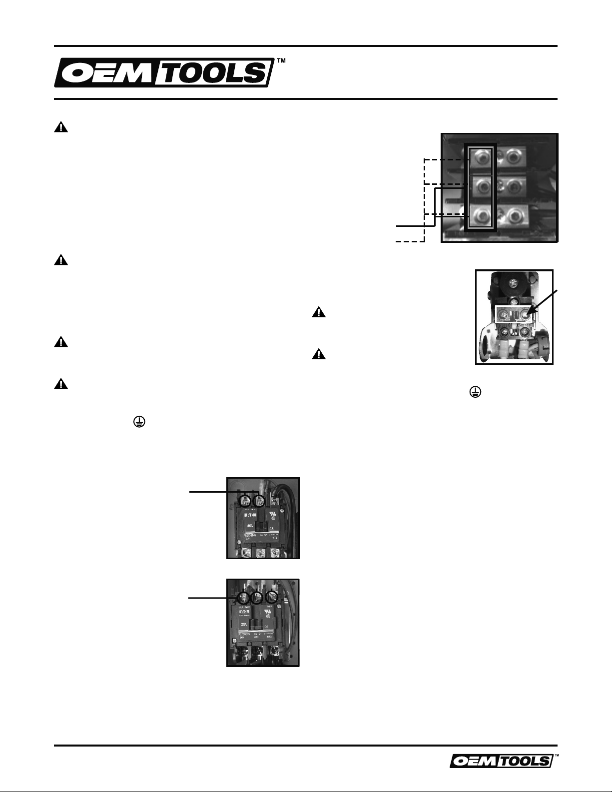
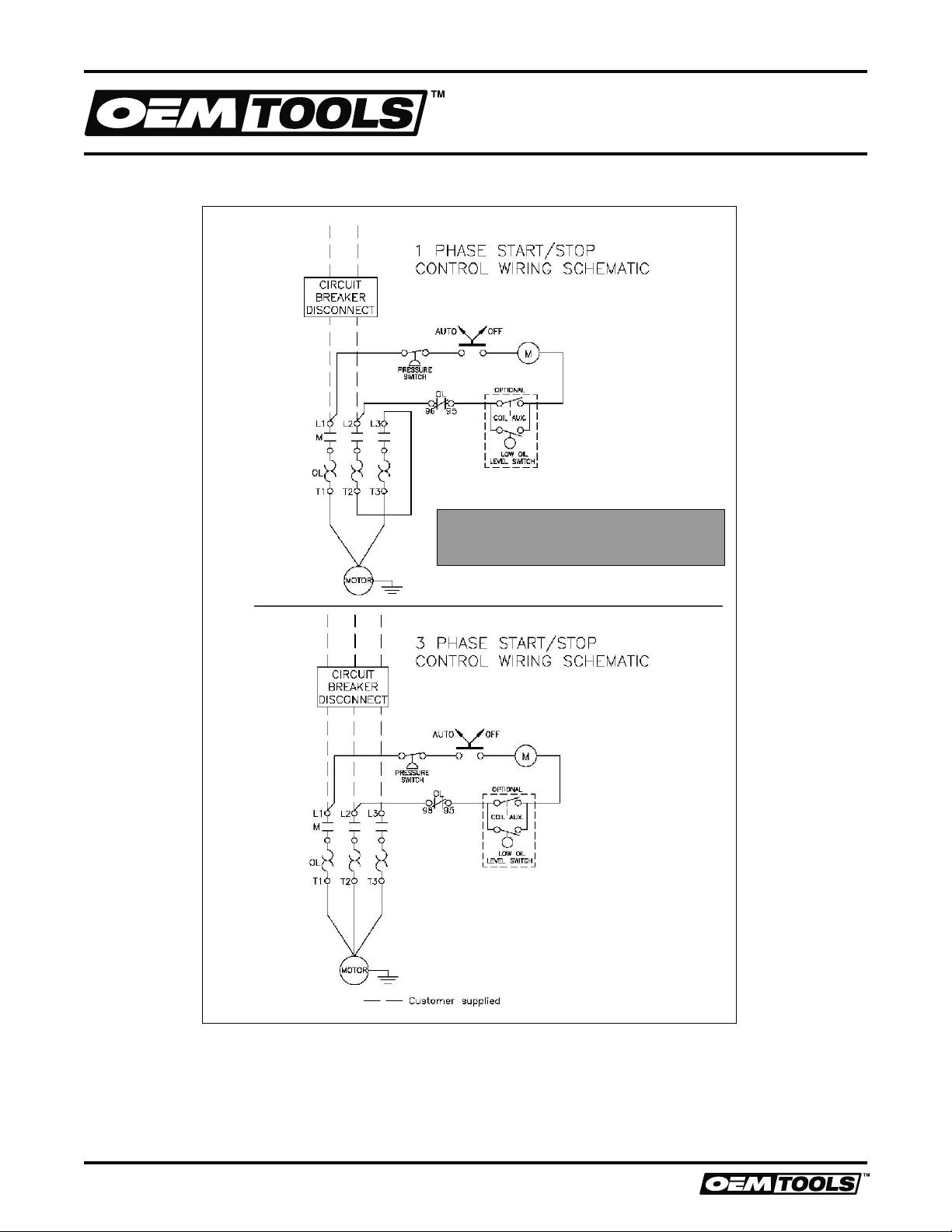
12.The compressor should be located where it can be
directly wired to a circuit breaker. The compressor
should be wired by a qualified electrician.
13.Never store flammable liquids or gases in the
vicinity of an operating compressor.
14.DO NOT locate the compressor air inlet near steam,
paint spray, sandblasting areas or any other source
of contamination. The debris could damage the
motor and pump.
15.Wear safety glasses (meeting ANSI Z87.1 or in
Canada CSA Z94.3-99) and use hearing protection
when operating the unit. Everyday glasses are not
safety glasses.
16.Wear shoes to prevent shock hazards.
17.Tie back long hair.
WARNING
18.Keep fingers away from running compressor. Fast
moving and hot parts may cause injury and/or
burns.
WARNING
19.Be careful when touching the exterior of
compressor, pump, motor and air lines; they may
become hot enough to cause injury.
WARNING
20.Never operate the compressor without a belt guard.
The compressor can start automatically without
warning. Personal injury or property damage could
occur from contact with moving parts.
CAUTION
21.The compressor may be hot even if the unit is
stopped.
WARNING
22.Use of a mask or respirator per chemical
manufacturers’ instructions may be necessary if
there is a chance of inhaling toxic fumes. Read
mask and respirator instructions carefully. Consult
a safety expert if you are not sure about the use of
certain masks or respirators.
BEFORE USING THE AIR COMPRESSOR
Air compressors are utilized in a variety of air
system applications. Because air compressors and
other components (hoses, connectors, air tools,
spray guns, etc.) make up a high pressure pumping
system, the following safety precautions should be
observed at all times.
INSPECT YOUR COMPRESSOR
1. To reduce the risk of injury from accidental starting,
turn switch off and disconnect the power before
checking it.
2. If any part is missing, bent or broken in any way, or
any electrical part does not work properly, keep the
compressor off and disconnected.
3. Check hoses for weak or worn condition before
each use, making certain all connections are
secure. DO NOT use if defect is found.
WARNING
DO NOT operate compressor if damaged during
shipping, handling or use. Damage may result in
bursting and cause injury or property damage.
WARNING
This compressor is not designed for and should not be
used in breathing air applications.
WHEN INSTALLING OR MOVING THE COMPRESSOR
This compressor is extremely top heavy. The
compressor must be bolted to the floor with vibration
pads before operating to prevent equipment damage,
injury or death. DO NOT tighten bolts completely as
this may cause stress to the tank welds.

3
Operating Instructions and Parts Manual 26100, 26101, 26102, 26103, 26104, 26105 and 26106
3/17
2017 OEMTOOLS™
AIR COMPRESSOR
WARNING
DO NOT secure compressor with toggle bolts into
drywall. Drywall sheeting or plaster will not support the
weight of the compressor.
Always shut off gas valve before moving gas drive
compressors.
WARNING
Never use plastic (PVC) pipe for compressed air.
Serious injury or death could result.
CAUTION
Never use the shipping skid for mounting the compressor.
NOTICE
Electric Compressors are not suitable for outdoor
installation.
NOTICE
Gasoline Compressors must be operated outdoors,
sheltered from the weather.
WARNING
Never install a shut off valve between the compressor
pump and tank. Personal injury and/or equipment
damage could occur.
FOLLOW THE SAFETY PRECAUTIONS FOR
ELECTRICAL CONNECTIONS
1. Follow all local electrical and safety codes, as
well as the National Electric Code (NEC) and the
Occupational Safety and Health Act (OSHA).
2. Wiring and fuses should follow electrical codes,
current capacity and be properly grounded.
3. Protect wires from contact with sharp objects.
CAUTION
All electrical connections should be made by a
qualified electrician.
WHEN OPERATING
1. DO NOT exceed the pressure rating of any
component of the system.
2. Release pressure within the system slowly to
prevent flying dust and debris.
3. If the equipment starts to abnormally vibrate,
STOP the compressor immediately and check
for the cause.
WARNING
Never change the safety valve or pressure switch
settings. Keep safety valve free from paint and other
accumulations. See compressor specification decal
for maximum operating pressure. DO NOT operate
with the pressure switch set higher than the maximum
operating pressure.
SPRAYING PRECAUTIONS
WARNING
Never point a spray gun at yourself or any other
person or animal. Accidental discharge may result in
serious injury.
REDUCE THE RISK OF DANGEROUS
ENVIRONMENT
WARNING
Extreme caution should be taken when spraying
flammable liquids as the spark from a motor or
pressure switch may cause a fire or explosion. Ample
ventilation must be provided.
WARNING
Spray in a well-ventilated area to keep fumes from
collecting and causing serious injury and fire hazards.
1. DO NOT spray in the vicinity of open flames or
other places where a spark can cause ignition.
2. DO NOT smoke when spraying paint, insecticides,
or other flammable substances.
BE INFORMED ABOUT THE MATERIALS YOU USE
1. When spraying with solvents or toxic chemicals,
follow the instructions provided by the chemical
manufacturer. Consult a safety expert if unsure
about the use of masks or respirators.
2. If the material you intend to spray contains
trichloreoethane and methylene chloride, do
not use accessories that contain aluminum or
galvanized materials, as these chemicals can react
with galvanized components causing corrosion
and weakening equipment. Use stainless steel
accessories.
PERFORM THESE MAINTENANCE OPERATIONS
1. Do regular maintenance; keep all nuts, bolts,
and screws tight, to be sure equipment is in safe
working condition.
2. Inspect tank yearly for rust, pin holes or any other
imperfections that could cause it to become unsafe.
WARNING
NEVER attempt to repair or modify a tank! Welding,
drilling or any other modification will weaken the tank
resulting in damage from rupture or explosion. Always
replace worn, cracked or damaged tanks.
3. Clean electrical equipment with an approved
cleaning agent, such as a dry, non-flammable
cleaning solvent.
4. Drain tanks of moisture after each day’s use. If unit
will not be used for awhile, it is best to leave the
drain cock open until such time as it is to be used.
This will allow moisture to completely drain out and
help prevent corrosion of inside of tank.

4
Operating Instructions and Parts Manual 26100, 26101, 26102, 26103, 26104, 26105 and 26106
3/17
2017 OEMTOOLS™
AIR COMPRESSOR
5. Always disconnect from power source before
working on or near a motor, or its connected load.
If power disconnect point is out of sight, secure it in
the “OFF” position and tag it to prevent unexpected
application of power.
WARNING
Disconnect power and depressurize system before
servicing air compressor. Slightly open drain cock after
shutting off compressor.
DAILY
Check oil level at sight glass. Oil level should be 1/2 to
slightly higher in the oil sight glass.
Drain moisture from tank.
Verify the pressure switch unloader is working
by listening for a brief hissing sound when the
compressor shuts off.
Visually check the compressor for loose parts, excessive
noise or vibration. Tighten any necessary part.
MONTHLY
(Make sure the main power is off.) Check the belts for
tension. Belts should not move up and down when the
compressor runs and when stopped, should not have
more than ½ in of play when depressed. Be careful not
to over tighten belts during adjustment.
Remove and check air filter, replace if necessary.
Change oil every 3 months or 300 hours. A compressor
grade 30 Wt. non-detergent oil should be used. 40 Wt.
non-detergent for single stage.
TYPICAL COMPRESSOR INSTALLATION
Chart 1a
Vibration Pad
Compressor
Leg
Lag Bolt
Floor
Flat
Washer
Shim
(If Necessary)
Flex
Hose
Air
Dryer
To Air System
Regulator
GLOSSARY OF TERMS
AIR FILTER - Porous element contained within a
metal or plastic housing attached to the compressor
cylinder head which removes impurity from the intake
air of the compressor.
AIR TANK - Cylindrical component which contains
the compressed air.
CHECK VALVE - Device which prevents compressed
air from flowing back from the air tank to the
compressor pump.
ELECTRIC MOTOR - Device which provides the
rotational force necessary to operate the compressor
pump.
PRESSURE GAUGE - Device which shows the tank
or regulated pressure of the compressed air.
PRESSURE SWITCH - Device which automatically
controls the on/off cycling of the compressor. It stops
the compressor when the cut-off pressure in the tank
is reached and starts the compressor when the air
pressure drops below the cut-in pressure.
PSI (POUNDS PER SQUARE INCH) - Measurement
of the pressure exerted by the force of air. The
actual PSI is measured by a pressure gauge on the
compressor.
PUMP - Device which produces the compressed air
with a reciprocating piston contained within a cylinder.
SAFETY VALVE - Device which prevents air pressure
in the air tank from rising over a predetermined limit.
THERMAL OVERLOAD SWITCH - Device,
integrated into the electric motor winding, which
automatically “shuts off” the compressor if the
temperature of the electric motor exceeds a
predetermined limit.
Overload
Adjustment
+
-
Vibration Pads (See Chart 1a)

5
Operating Instructions and Parts Manual 26100, 26101, 26102, 26103, 26104, 26105 and 26106
3/17
2017 OEMTOOLS™
AIR COMPRESSOR
DO NOT MAKE CONNECTIONS AT THE PRESSURE
SWITCH (UNITS WITH MAGNETIC STARTERS)
SINGLE PHASE
Incoming power should be
connected to L1 and L2 at
the top of the magnetic starter
WIRING
WARNING
ALL ELECTRICAL WIRING SHOULD BE DONE
BY A QUALIFIED ELECTRICIAN
GENERAL INFORMATION
Adequate wiring and motor protection should be
provided for all stationary compressors. Wiring used
for other machinery should not be used. A qualified
electrician familiar with local electrical codes in your
area should be used. Size supply wiring per NEC
(National Electric Code) requirements.
WARNING
To reduce the risk of electrical hazards, fire hazards
or damage to the compressor, use proper circuit
protection. Your compressor is wired at the factory
for operation using the voltage shown. Connect the
compressor to a power source with the correct breaker
size.
CAUTION
Overheating, short circuiting and fire damage will result
from inadequate wiring.
WARNING
Electrical connections must be properly grounded.
Ground connections should be connected at the
grounding screw.
.
DUPLEX WIRING
(INSIDE CONTROLLER ON THE BOTTOM)
THREE PHASE
Incoming power should be
connected to L1, L2 and L3 at
the top of the magnetic starter
FOR MODELS WITHOUT MAGNETIC STARTER
Incoming power should
be connected to the
post marked (Line)
WARNING
DO NOT make connections
on prewired posts marked (Motor)
WARNING
Electrical connections must be
properly grounded. Ground connections should be
connected at the grounding screw.
SINGLE PHASE
THREE PHASE

6
Operating Instructions and Parts Manual 26100, 26101, 26102, 26103, 26104, 26105 and 26106
3/17
2017 OEMTOOLS™
AIR COMPRESSOR
WIRING
Single and Three Phase
With Mag Starter

7
Operating Instructions and Parts Manual 26100, 26101, 26102, 26103, 26104, 26105 and 26106
3/17
2017 OEMTOOLS™
AIR COMPRESSOR
WIRING
Single and Three Phase
Duplex

8
Operating Instructions and Parts Manual 26100, 26101, 26102, 26103, 26104, 26105 and 26106
3/17
2017 OEMTOOLS™
AIR COMPRESSOR
WIRING
Single and Three Phase
QP

9
Operating Instructions and Parts Manual 26100, 26101, 26102, 26103, 26104, 26105 and 26106
3/17
2017 OEMTOOLS™
AIR COMPRESSOR
STARTING THE COMPRESSOR
Prior to actually running the compressor, check the
following items:
Crankcase oil - Make sure the sight glass shows ½ full
or slightly above.
Make sure all rags, tools, oil, etc. are away from the unit.
Open the air system to free it of any pressure.
Switch the compressor on for a few revolutions to
make sure the rotation is correct. Correct rotation is
clockwise when facing the sight glass on the pump.
Operate the compressor for a few minutes unloaded
(air system open) then allow the compressor to pump
up. Make sure the electrical pressure switch properly
switches off the compressor according to the setting
desired. 175 for Two Stage.
(135 PSI - Single Stage or 165 PSI - RCP-561VNS)
CAUTION
Make sure the pressure in the tank does not exceed its
rating. Single Stage units - 135 PSI Two Stage units at
a maximum of 175 PSI.
(165 for Model 8090255525)
If the pressure gauge indicates a pressure that is
higher than these maximum pressures, shut off
compressor immediately and call your distributor.
(DUPLEX MODELS)
ALTERNATING RUNNING PROCEDURE
Initial power to the controller takes about 5 seconds to
power up and run Motor A will start and then Motor B
after a 10 second delay
Both motors will run until unit reaches cutoff pressure
(175 PSI)
Each time the unit starts after initial start, the “Lead”
motor will alternate
If the unit runs for more than 5 minutes, the second
Motor will come on and run until the unit reaches
cutoff pressure
The second motor will also come on if the air demand
is higher than one pump/motor can produce and the
pressure drops to around 135 PSI (10 sec. delay)
A OR B RUNNING PROCEDURE
By selecting A or B on the switch,
either Pump/Motor A or Pump/Motor B
will operate independently, as a
simplex compressor.
(GAS DRIVE MODELS)
PLEASE REFER TO YOUR ENGINE OPERATION
MANUAL FOR PROPER STARTING INSTRUCTIONS.
GASOLINE DRIVEN COMPRESSORS ARE EQUIPPED
WITH A COLD START VALVE FOR LOADLESS
STARTS.
NOTE: IN SOME INSTANCES, IT STILL MAY BE
NECESSARY TO LIFT THE TOGGLE ON THE
UNLOADER/PILOT VALVE TO RELIEVE THE HEAD
PRESSURE. See Figure 1 below.
BATTERY CONNECTION INSTRUCTIONS FOR
ELECTRIC START ENGINES
Note: Make sure to follow instructions carefully to
avoid a short and possible damage to the starter
solenoid and/or battery.
1. Connect the positive (+) terminal on the battery to
the starter solenoid.
2. Connect the negative (-) terminal on the battery
to an engine mounting bolt or other acceptable
ground connection.
Always connect the positive (+) battery cable to the
starter solenoid before connecting the negative (-)
battery cable.
NUMBER 2 WIRE OR LARGER IS REQUIRED
BATTERY
(12 Volt)
(+)(-)
GROUND
Starter Solenoid
COLD START PROCEDURE
(GASOLINE ENGINE UNITS)
WARNING
DO NOT operate gasoline engine units in an enclosed area.
· Release any remaining tank pressure by slowly
opening the manual drain valve.
· Turn on the engine gasoline supply.
· Put the choke in the “On” position.
· Close the service valve and put Unloader lever in
the “unload” (A) Position for Briggs and Stratton
and Honda engine driven models, or the “load” (B)
position for Kohler engine models.
· Start the engine, release the choke, and allow the
engine to warm up for two to three minutes.
· Return the unloader lever to the “load” (B) position
on Briggs and Stratton and Honda driven models.
NOTE: Turn the gasoline supply off when the
compressor is not being used.
NORMAL
OPERATION
FIGURE 1

10
Operating Instructions and Parts Manual 26100, 26101, 26102, 26103, 26104, 26105 and 26106
3/17
2017 OEMTOOLS™
AIR COMPRESSOR
WARNING
Oil and moisture residue must be drained from the air
receiver daily or after each use. Accumulations of oil
residue in the receiver can be ignited by embers of
carbon created by the heat of compression causing an
explosion, damage to property and injury to personnel.
WARNING
DO NOT open a manual tank drain valve on any air
tank containing more than 30 PSIG of air pressure!
WARNING
Never attempt to relieve an air tank by removing a pipe
plug or any other system component!
AIR TANK INSPECTION
Recommended Air Tank Inspection Intervals The
factory recommends that all air tanks be inspected at
scheduled intervals. Refer to Recommended Air Tank
Inspection Intervals Table for relative information.
Refer to federal, state or provincial, or local codes for
mandatory air tank maintenance information.
MANUALLY DRAINING AN AIR TANK:
Step 1) Disconnect and lockout the compressor
from the power source (electric models) or
disconnect the spark plug wire from the spark
plug (gas engine models).
Step 2) Tank(s) subjected to freezing temperatures
may contain ice. Store the compressor in
a heated area before attempting to drain
moisture from the tank(s). Reduce the air
pressure in the tank to 30 PSIG by pulling
the pressure relief valve ring.
Step 3) Slowly open the drain valve and allow the
moisture and air mixture to drain from the tank.
Step 4) Once the moisture has been completely
drained, close the drain valve.
TANK SPECIFICATIONS
PUMP SPECIFICATIONS
RECOMMENDED AIR TANK INSPECTION
Pump Model Pump P/N Cyl. No. Stages
PAT24 4116091136 2 1
PAT38 4116091337 2 1
T39 4116090019 2 2
T29S 4116090112 2 2
B5900 4116090137 2 2
C1 1312202800 2 2
C2 1312202700 4 2
Pump
Model
Cyl. Diam. In. (mm) Stroke
In.
(mm)
Max
RPM
Oil Cap.
Qt. (L)
Displacement
@ max RPM
1st Stg 2nd Stg CFM L/M
PAT24 2.48 (63) N/A 1.50 (38) 1400 .56 (0.53) 11.71 331.59
PAT38 2.48 (63) N/A 2.36 (60) 1400 .91 (.86) 18.49 523.58
T39 4.13 (105) 2.05 (52) 2.95 (60) 1400 1.09 (1.03) 32.02 906.63
T29S 3.74 (85) 1.97 (45) 1.97 (45) 1400 1.44 (1.36) 17.53 496.50
B5900 4.13 (105) 2.16 (55) 2.16 (55) 1400 1.72 (1.63) 23.44 663.84
C1 4.13 (105) 2.16 (55) 3.5 (89) 1000 1.31 (1.24) 27.13 768.33
C2 4.13 (105) 2.16 (55) 3.5 (89) 900 1.5 (1.42) 48.84 1382.99
Pump
Model
Bolt Torque Ft./Lbs. (NM)
Conrod Head Cylinder Bearing
Housing Flywheel
PAT24 N/A 18-20 (24-27) 18-20 (24-27) 5-7 (7-10) 18-20 (24-27)
PAT38 N/A 18-20 (24-27) 18-20 (24-27) 5-7 (7-10) 18-20 (24-27)
T39 20-22 (27-30) 30-33 (40-45) 16-19 (22-26) 19-22 (26-30) 34-37 (46-50)
T29S 18-20 (24-27) 18-20 (24-27) 18-20 (24-27) 5-7 (7-10) 18-20 (24-27)
B5900 18-20 (24-27) 18-20 (24-27) 18-20 (24-27) 5-7 (7-10) 18-20 (24-27)
C1 34-37 (46-50) 34-37 (46-50) 19-27 (26-37) 14-19 (19-26) 47-57 (64-77)
C2 34-37 (46-50) 34-37 (46-50) 19-27 (26-37) 14-19 (19-26) 47-57 (64-77)
Tank
Capacity
Horizontal
or Vertical
Minimum Allowance Call Visually
Inspect
Hydrostatically
Inspect
Head Shell
8 Gal. Horizontal 0.096 0.094 Yearly 10 Years
8 Gal. Twin Horz. 0.098 0.098 Yearly 10 Years
10 Gal. Twin Horz. 0.118 0.118 Yearly 10 Years
20 Gal. Horizontal 0.094 0.094 Yearly 10 Years
26 Gal. Vertical 0.094 0.094 Yearly 10 Years
30 Gal. Horizontal 0.109 0.098 Yearly 10 Years
60 Gal. Vertical 0.094 0.094 Yearly 10 Years
80 Gal. Vertical 0.149 0.133 Yearly 10 Years
80 Gal. Horizontal 0.109 0.133 Yearly 10 Years
120 Gal. Vertical 0.163 0.199 Yearly 10 Years
120 Gal. &
Duplex
Horizontal 0.131 0.159 Yearly 10 Years
200 Gal.
Duplex
Horizontal 0.163 0.199 Yearly 10 Years
Volume Max Pressure. Discharge Conn
Gal. Liter PSI Bar NPT
20H 76 150 10.345 1/4"
26V 99 150 10.345 1/4"
60V 228 170 11.724 1/2"
2X4 2X15.2 200 13.793 3/8"
2X5 2X19 200 13.793 3/8"
80H 228 200 13.793 3/4"
80V 300 200 13.793 3/4"
30H 114 200 13.793 3/4"
120V 456 200 13.793 3/4"
120H 456 200 13.793 3/4"
120D 456 200 13.793 3/4"
200D 760 200 13.793 3/4"

11
Operating Instructions and Parts Manual 26100, 26101, 26102, 26103, 26104, 26105 and 26106
3/17
2017 OEMTOOLS™
AIR COMPRESSOR
Low discharge pressure 1. Compressor too small for application
2. Air leaks
3. Restricted intake air
4. Blown gasket(s)
5. Broken or misaligned valves
1. Reduce air demand or use a compressor with
more air capacity.
2. Listen for air leaks. Apply a soap solution to all
fittings and connections. Bubbles will form at
points of leakage. Tighten or replace fittings or
connections.
3. Clean or replace air filter.
4. Replace necessary gaskets.
5. Remove head and inspect for broken or
misaligned valves. Replace valves, if necessary.
Excessive noise knocking 1. Loose drive pulley or flywheel
2. Low on oil
3. Worn connecting rod or connecting rod
bearing
4. Noisy check valve
1. Tighten drive pulley or flywheel bolt.
2. Check for proper oil level. Low or dirty oil may
cause bearing damage.
3. Replace connecting rod and/or connecting rod
bearings.
4. Replace check valve.
Excessive oil carryover 1. Worn piston rings
2. Restricted intake air
3. Too much oil in compressor
4. Incorrect oil viscosity
1. Replace with new piston rings.
2. Clean or replace air filter.
3. Drain oil to proper oil level.
4. Use a quality non-detergent 30 or 40 wt oil
specified for each model (Page 4).
Water in tank and/or discharge line 1. Normal. Amount of water will increase as
humidity in the air increases.
1. Drain tank at least once per day.
2. Add an in-line filter to reduce moisture in the
air line.
Will not run or motor hums 1. Low voltage
2. Malfunctioning pressure switch
3. Malfunctioning check valve
1. Check voltage with volt meter across both
legs of incoming power. Check reset button
on motor.
2. Repair or replace pressure switch.
3. Replace check valve or pressure switch.
Breaker or reset repeatedly trips 1. Incorrect breaker size
2. Low voltage
3. Malfunctioning motor
4. Loose electrical connections
5. Malfunctioning pressure switch
6. Malfunctioning check valve
1. Make sure the breaker is sized properly. See
page 6 in this manual.
2. Check voltage with volt meter across both
legs of incoming power.
3. Replace motor.
4. Check all electrical connections.
5. Adjust or replace pressure switch.
6. Replace check valve.
Tank does not hold pressure when not
running and shut off valve is closed
1. Malfunctioning check valve
2. Loose fittings or connections
3. Crack or pin hole in tank
1. Replace check valve.
2. Tighten or replace fittings or connections.
3. Replace tank. Do not attempt to repair tank.
Pressure switch unloader constantly
leaking air
1. Malfunctioning check valve 1. Replace check valve if unloader bleeds
constantly.
Pressure switch not unloading 1. Malfunctioning pressure switch 1. Replace pressure switch if it does not release
air pressure briefly when unit shuts off.
Excessive vibration 1. Improper installation
2. Loose belts
3. Misaligned flywheel or drive pulley
1. Make sure unit is mounted on a level surface
with vibration pads.
2. Replace belts. Align and tighten properly.
3. Align flywheel and drive pulley.
Overheating 1. Compressor too small for application
2. Cooling surfaces dirty
3. Improper cooling
1. Reduce air demand or use a compressor with
more air capacity.
2. Clean all cooling surfaces of dirt and dust.
3. Install compressor in an area with adequate cool
dry air.
CAUTION Install a new head gasket
each time head is removed
DANGER DO NOT remove check valve
with air pressure in tank
DANGER DO NOT remove check valve
with air pressure in tank
DANGER DO NOT remove check valve
with air pressure in tank
DANGER DO NOT remove check valve
with air pressure in tank
DANGER DO NOT remove check valve
with air pressure in tank
DANGER DO NOT remove check valve
with air pressure in tank
TROUBLESHOOTING GUIDE

12
Operating Instructions and Parts Manual 26100, 26101, 26102, 26103, 26104, 26105 and 26106
3/17
2017 OEMTOOLS™
AIR COMPRESSOR
Chicago Pneumatic Full Two-Year Warranty Statement
The Company warrants that the Equipment manufactured by it and delivered hereunder shall be free from
defects in material and workmanship for a period of twenty four (24) Months from the date of initial start-up, or
twenty four (24) Months from the date of shipment from the manufacturer, whichever occurs first. The foregoing
warranty period shall apply to all Equipment, except for the following: (A) all two stage reciprocating stationary
models are warranted for the earlier of twenty-four (24) Months from the date of initial operation or thirty (30)
months from date of shipment from the manufacturer. (B) Replacement parts will be warranted for three (3)
months from the date of shipment from the manufacturer. Should the failure to conform to this warranty be
reported in writing to the Company within said period, the Company shall, at its option, correct such non -
conformity by suitable repair to such Equipment, or furnish a replacement part F.O.B point of shipment, provided
that the Purchaser has installed, maintained, and operated such Equipment in accordance with good industry
practices, and has complied with specific recommendations of the Company. Accessories and equipment
furnished by the Company, but manufactured by others, shall carry whatever warranty the manufacturer
conveyed to the Company and which can be passed on to the Purchaser. The Company shall not be liable for
any repairs, replacements, or adjustments to the Equipment, or any costs of labor performed by the Purchaser
without the Company’s prior written approval.
The Company makes no performance warranty unless specifically stated within its proposal, and the effects
of corrosion, erosion, and normal wear and tear are specifically excluded from the Company’s warranty. In the
event performance warranties are expressly included, the Company’s obligation shall be to correct in the manner
and for the period of time provided above.
THE COMPANY MAKES NO OTHER WARRANTY OR REPRESENTATION OF ANY KIND WHATSOEVER,
EXPRESSED OR IMPLIED, EXCEPT THAT OF TITLE, AND ALL IMPLIED WARRANTIES OF MERCHANTABILITY
AND FITNESS FOR A PARTICULAR PURPOSE, ARE HEREBY DISCLAIMED. THIS WARRANTY SUPERSEDES
ALL PREVIOUS WARRANTY STATEMENTS.
Correction by the Company of non-conformities, whether patent or latent, in the manner and for the period of
time provided above, shall constitute fulfillment of all liabilities of the Company and its distributors for such non-
conformities with respect to, or arising out of such Equipment.
LIMITATION OF LIABILITY
THE REMEDIES OF THE PURCHASER SET FORTH HEREIN ARE EXCLUSIVE, AND THE TOTAL LIABILITY OF
THE COMPANY, ITS DISTRIBUTORSAND SUPPLIERS WITH RESPECT TO CONTRACT OR THE EQUIPMENT
AND SERVICES FURNISHED IN CONNECTION WITH THE PERFORMANCE OR BREACH THEREOF, OR FROM
THE MANUFACTURE, SALE, DELIVERY, INSTALLATION, REPAIR OR TECHNICAL DIRECTION COVERED OR
FURNISHED UNDER CONTRACT, WHETHER BASED ON CONTRACT, WARRANTY, NEGLIGENCE, INDEMNITY,
STRICT LIABILITY OR OTHERWISE, SHALL NOT EXCEED THE PURCHASE PRICE OF THE EQUIPMENT UPON
WHICH SUCH LIABILITY IS BASED.
THE COMPANY, ITS DISTRIBUTORS AND ITS SUPPLIERS SHALL IN NO EVENT BE LIABLE TO THE
PURCHASER, ANY SUCCESSORS IN INTEREST, OR ANY BENEFICIARY OR ASSIGNEE OF THE CONTRACT
FOR ANY CONSEQUENTIAL, INCIDENTAL, INDIRECT, SPECIAL OR PUNITIVE DAMAGES ARISING OUT OF
THIS CONTRACT OR ANY BREACH THEREOF, OR ANY DEFECT IN, OR FAILURE OF, OR MALFUNCTION OF
THE EQUIPMENT, WHETHER OR NOT BASED ON LOSS OF USE, LOST PROFITS OR REVENUE, INTEREST,
LOST GOODWILL, WORK STOPPAGE, IMPAIRMENT OF OTHER GOODS, LOSS BY REASON OF SHUTDOWN
OR NON-OPERATION, COST OF PURCHASE OF REPLACEMENT POWER, OR CLAIMS OF PURCHASER OR
CUSTOMERS OF PURCHASER FOR SERVICE INTERRUPTION, WHETHER OR NOT SUCH LOSS OR DAMAGE
IS BASED ON CONTRACT, WARRANTY, NEGLIGENCE, INDEMNITY, STRICT LIABILITY OR OTHERWISE.
For warranty information call Chicago Pneumatic 1-886-869-3114 (Parts and Technical)
CONTACT US
3580 E. Raines Road, Suite 3, Memphis, TN 38118
Tel: 1-866-458-2472
www.oem-tools.com
This manual suits for next models
6
Table of contents
Popular Air Compressor manuals by other brands

imcoinsa
imcoinsa 04606 Instruction book

Parkside
Parkside PKZ 180 B2 Translation of the original instructions

Craftsman
Craftsman 919.167802 user manual

Atlas Copco
Atlas Copco GA 11 VSD Instruction book

Craftsman
Craftsman 919.165180 owner's manual

Schneider Airsystems
Schneider Airsystems UNM 410-10-50 W Original operating manual