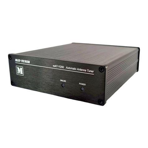
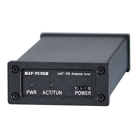
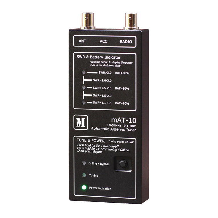
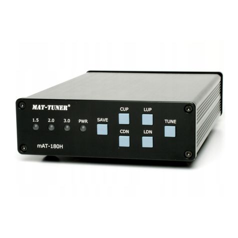
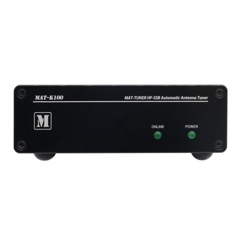
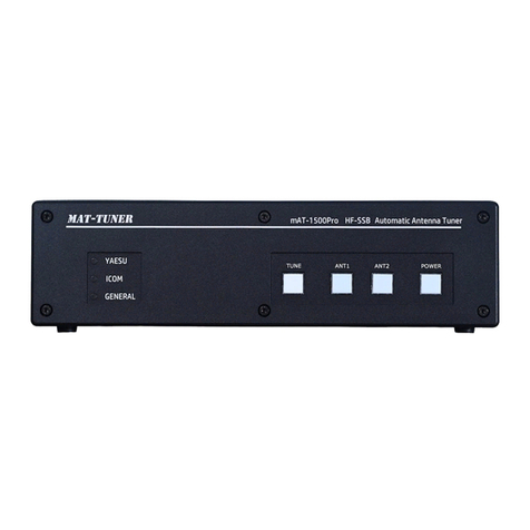
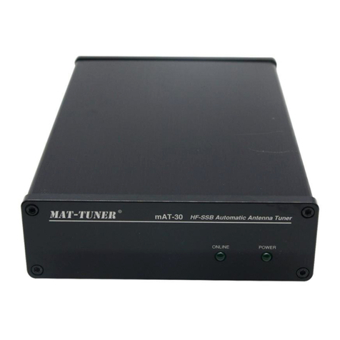
MAT-TUNER® Instruction Manual
USABLE TRANSCEIVERS
Most HF transceivers can use mAT-125E. They only need to satis y two conditions: the RF
power level can be adjusted below 20 W, and they have at least one o AM, FM, CW, FSK, RTTY
modes to output constant carrier.
It should be noted that in the tuning process, a larger VSWR can be detected by the
transceiver. Because the output power o the transceiver is very low, this high VSWR should not
damage the transceiver. Some transceivers are very sensitive to this high VSWR even at low
power levels and they may turn o the transmitting carrier, which will cause the tuning to stop.
Yaesu transceivers are particularly susceptible to this issue. For Yaesu, the mAT-30 tuner will not
cause the radio to stop transmitting in the presence o higher VSWR while tuning, even at low
power output.
INSTALLATION
1. Connect the HF/50 MHz antenna jack on the transceiver to the “RF IN” jack on the back o
the mAT-125E, using a 50 ohm coax cable rated 120 watts or greater.
2. Connect the antenna eedline coax to the “ANTENNA” jack on the rear o the mAT-125E.
3. Grounding the mAT-125E tuner will enhance its per ormance and sa ety. We recommend
that you connect your tuner to a suitable ground; a common ground rod connected to buried
radials is pre erred, but a single ground rod or a cold water pipe can also be used. We strongly
recommend the use o a properly installed, high quality lightning arrestor on all antenna cables
O ERATION
As with other general tuners, a constant RF signal o 1-20 watts power level is needed to be
present at the tuner input during the tuning cycle. This signal should be CW, FM, FSK, or RTTY.
The power level o the input RF signal must not be greater than 20 watts, otherwise it will shorten
the li e o the tuning cycle, and the tuner can be damaged.
The mAT-125E ha two modes o operation: automatic and semi-automatic. Users can easily
switch between the two modes o work by using multi- unction combination buttons.
Automatic Mode: When the RF signal is input into the mAT-125E, the tuner veri ies that the
power at its input (FORWARD) is within the prede ined range (1-20W). Power above this range
can damage the relays due to hot switching, while power below the prede ined range can cause
inaccurate tuning. I the tune power is within the speci ied range, the tuner captures a 20ms
sample o the signal. The sample signal requency is divided by 128 and measured by a counter.
The tuner reads the tuning data corresponding to the measured requency rom its internal memory
(such data exists i tuning was previously per ormed or this requency). The tuner sets the tuning
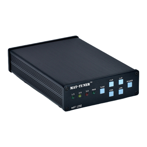
network according to that data and measures the resulting VSWR, and displays the current VSWR
by the LED o the ront panel. Even i SWR is higher than 2:1 the tuning cycle will not be
activated unless the TUNE key is pressed and released.
Semi-automatic: When the RF signal is input into the mAT-125E, the tuner only measures the
current VSWR and displays the results through the LED on the ront panel. A tuning cycle is not
initiated until the [TUNE] key is pressed. When the [TUNE] key is pressed and released, similar
to the automatic mode, the tuner measures the requency o the input signal, reads the
con iguration data rom the corresponding memory, and con igures the LC tuning network. A ter
completing the above operation, the tuner will measure the current VSWR. I VSWR<1.5,the
tuning is completed. I it is higher, a new tuning cycle is started. When the tuner completes the
tuning process it stores the tuning network data in memory in a location corresponding to the
current requency.
3 / 5
