Matchless 1949 CLUBMAN G3L User manual

MATCHLESS
MOTOR CYCLES
PROPRIETORS : ASSOCIATED MOTOR CYCLES LIMITED
PLUMSTEAD · LONDON · S.E.18
MAINTENANCE
MANUAL
AND
INSTRUCTION
BOOK
for
1 9 4 9
350 c
.
c. and 500 c.c.
CLUBMAN MODELS
O
.
H.V., MA TCHLESS
EDITION CM-7


Supplied free, upon application, with each new motor cycle. Replacement Copies, 2/6 each
EDITION CM-7
A — M
Matchless Motor Cycles
MAINTENANCE MANUAL
AND INSTRUCTION BOOK
for 1949
Models 49/G3L and 49/G80L
Compiled and Issued by the Manufacturers :
MATCHLESS MOTOR CYCLES
(Proprietors: ASSOCIATED MOTOR CYCLES LIMITED)
Registered Offices:
PLUMSTEAD ROAD, PLUMSTEAD
LONDON, S.E.18 .. ENGLAND
Nearest Station :
WOOLWICH ARSENAL
(Southern Railway)
Factories :
BURRAGE GROVE and MAXEY ROAD
PLUMSTEAD, S.E.18
Telegrams and Cables: "MATCHLESS, WOL-LONDON"
Telephone : WOOIwich 1 22 3 (5 Lines)
Codes : A.B.C. 5th and 6th Edition ; Bentley's ; and Private Codes
All correspondence to :—
MATCHLESS MOTOR CYCLES, PLUMSTEAD ROAD, LONDON, S.E.18

1949 MATCHLESS "Clubman" MODELS
350 "CLUBMAN" Model G3L 500 "CLUBMAN" Model G80L
49/G3L — Bore 69 mm. Stroke 93 mm. Capacity 347 c.c.
49/G80L — Bore 82·5 mm. Stroke 93 mm. Capacity 498 c.c.
Motorcycling is one of the most economical and pleasurable
modes of transport. It is our sincere wish that every
" MATCHLESS" owner should obtain, from his mount, the
service, comfort and innumerable miles of low-cost travel
that we have earnestly endeavoured to build into it.
However, it must be remembered that although a motor cycle
is of simple design and construction, it is, nevertheless, a
highly specialised piece of engineering. In consequence, it
must be intelligently and efficiently maintained in order to
provide unfailing reliability.
In this book are non-technical instructions for carrying out
all the maintenance operations likely to be called for in
strenuous service and illustrations are provided to assist.
Neglect to make essential adjustments, only casual attention
to lubrication and the lack of periodical maintenance attention
will soon neutralise the best efforts of the designers and may
bring needless trouble to the owner.
We are always pleased to give " MATCHLESS " owners the
full benefit of our wide experience in matters relating to
motor cycles of our manufacture and in paragraph 113 will
be found details of the particulars that should be given us
when making such an enquiry.
MATCHLESS MOTOR CYCLES
INTRODUCTION
2

DATA
1 DATA
(a) Description.
Models
Engine number
Frame number
Cubic Capacity (Actual)
Cylinder bore
Stroke
Compression Ratio
Standard
"350"
"500"
350 & 500
350 & 500
350
500
350
500
350 & 500
350
500
500
Stamped on left-hand side of crankcase.
Stamped on right-hand side of seat lug.
(Below saddle).
347 Cubic Centimetres.
498 Cubic Centimetres.
69 Millimetres.
82.5 Millimetres.
93 Millimetres.
6.4 to 1.
6.2 to 1. (With plate fitted).
7.47 to 1. (No plate fitted).
(b) Capacities.
Front fork
Gear box
Oil tank
Petrol tank
10 fluid ounces, 284 c.c.
20 fluid ozs. (1 pint), 568 c.c.
4 pints.
3 gallons.
(c) Carburetter.
Main Jet size
Throttle size
Choke size
Taper needle
350
500
350
500
350
500
350
500
150.
180.
6/4.
29/4.
1 inch diameter.
1-3/32 inches diameter.
T-6-Std.
T-29-Std.
(d) Chains.
Front chain
Rear chain
Dynamo chain
Magneto chain
350
500
350 & 500
350 & 500
350 & 500
½"pitch,
½"pitch,
s"pitch,
a" pitch,
a" pitch,
.305 wide, 66 links.
.305 wide, 67 links.
.380 wide, 94 links.
.225 wide, 49 links.
.225 wide, 58 links.
B—M
Taper needle located in 3rd notch from top, 350, and 2nd from top, 500.
(Dynamo and Magneto chains are " endless.")
…
…
…
…
…
…
…
…
…
…
…
…
3

(e) Gear ratios (Touring).
Top
Third
Second
First
350 Solo.
Engine Sprocket,
18teeth
5.83 to
1
7.5 to
1
10.2 to
1
15.5 to
1
500 Solo.
Engine Sprocket,
21 teeth
5.0 to
1
6.4 to
1
8.8 to
1
13.4 to
1
500 Sidecar.
Engine Sprocket,
19teeth
5.4 to 1
7.0 to
1
9.6 to
1
14.6 to
1
(f) Gear Ratios (Competition).
Top
Third
Second
First
350 Solo.
Engine Sprocket,
6 teeth 17 teeth
6.56 6.13
8.38 7.93
14.42 12.91
20.94 19.58
500 Solo.
Engine Sprocket,
18 teeth 19 teeth
5.83
7.46
12.84
18.50
5.49
7.1
11.55
17.52
(g) Ignition setting.
The ignition setting, with the ignition control in the fully advanced position, is
½"before top dead centre.
(h) Sparking plug.
Type
Thread
Reach
Point gap
LODGE H-14,
14Millimetres.
½".
.020" to .025".
(i) Piston dimensions.
Top land
Second land
Third land
Top of skirt
Bottom of skirt
350
2.6877"
2.6962"
2.6962"
2.7172"
2.7177"
500
3.2145"
3.2260"
3.2190"
3.2485"
3.2490"
(j) Piston rings
All above measurements are subject to a toleration limit of + or — .0005".
Model
350
500
Diameter
2-23/32"
3¼"
Width of
Com-
pression
ring
z"
z"
Width of
Scraper
ring
8"
8"
Ring
gap
(Normal)
.006" to
.008"
.006" to
.008"
Maximum
permiss-
ible wear
.030"
.030"
Clearance
in
groove
.003"
.003"
Two compression and one scraper ring are fitted to each piston.
All piston rings supplied by us are "gapped " before despatch and therefore
are ready for immediate fitting and use.
…………………
… … … … … … …
… … … … … …
… … … … … …
… … … … … …
… …
… …
… …
… …
… …
… …
… …
…
4

(k) Spokes. (300 and 500).
(I) Valve timing. (350 and 500).
(m) Valves.
(n) Gear box ratios.
(o) Wheel sizes. (350 and 500).
(p) Weight Unladen.
Front, left side. 5 x"by 8g. by 10g. Butted.
Front, right side. 8 8" by 9g. by 11g. Butted.
Rear, both sides. 8 8" by 6g. by 9g. Butted.
Spoke lengths are measured under the head. (Not overall length).
Inlet valve opens 32° before top dead centre.
Inlet valve closes 63° after bottom dead centre.
Exhaust valve opens 65° before bottom dead centre.
Exhaust valve closes 30° after top dead centre.
(For checking, see Para. 49.)
Model
350
500
Clearance
(with cold
engine).
Nil.
Nil.
Inlet head
diameter
1-19/32"
1.687"
Exhaust
head
diameter
1½"
1.687"
Stem
diameter
a"
a"
Seat
angle
45°
45°
Valve head measurements are subject to a toleration limit of + or — 0005".
Valve stem actual measurement is minus .0035" to minus .0045" exhaust and .002"
to .003 ' inlet.
Standard Models
Top 1 to 1
3rd 1 to 1.28
2nd 1 to 1.76
1st 1 to 2.67
Competition Models
Top 1 to 1
3rd 1 to 1.28
2nd 1 to 2.09
1st 1 to 3.16
Touring Models:
Tyres. 26" by 3.25". (Front and back), 350 c.c. model.
26" by 3.25" Front, 26" by 3.50" Rear, 500 c.c. model.
Rims. 19" by 2½". (Front and back).
Front and rear rims are not interchangeable because the spoke nipple
diameters differ. Those used in the front are .225" in diameter and those
used in the rear are .250" in diameter.
Competition Models:
Tyres. 27" by 3.00" Front, 27" by 4.00" Rear.
Rims. 21" by 2¼" Front, 19" by 3" Rear.
Wheel bearing end play is .002".
350 c.c. Model — 340 lbs.
500 c.c. Model — 350 lbs.
5

CONTROLS
(1)
(2)
(3)
(4)
(5)
(6)
(7)
(8)
(9)
(10)
(11)
(12)
(13)
(14)
(15)
(16)
(17)
Throttletwistgrip.Twistinwardstoopen.Whenfullyclosedengineshould
justidlewhenhot.
Aircontrollever.Pullinwardstoincreaseairsupply.Onceset,whenengine
haswarmedup,requiresnoalterationfordifferentroadspeeds.Shouldbefully
closedtostartenginefromcold.
Ignitioncontrol.Advancesandretardsignitionpoint.Pullinwardstoadvance.
Retardtwo-fifthsoftotalmovementforstarting.
Valvelifterlever.Smallleverclosetoclutchlever.Liftsexhaustvalvefrom
seat,releasingcompressionincombustionchamber,enablingenginetobeeasily
rotatedforstarting.Alsousedforstoppingengineifthrottlestopisset
asadvisedinPara.(1)above.AlsoseePara.6.
Clutchlever.Largeleverinfrontoflefthand.Griptoreleaseclutchsothat
drivetorearwheelisdisconnected.Usedwhenmovingawayfromstandstill
andwhenchanginggear.
Frontbrakelever.Largeleverinfrontofrighthand.Griptooperatefront
wheelbrakeand,fornormalbraking,useinconjunctionwithrearbrakeappli-
cation.SeePara.9.
Rearbrakepedal.Depresswithleftfoottoapplyrearbrake.Applygently
anduseincreasingpressureasroadspeeddecreases.
Gearchangepedal.Controlsselectionofthefourspeeds,orratios,between
engineandrearwheelrevolutions,witha " free,"orneutral,position.See
Para.7 andIllustration3.
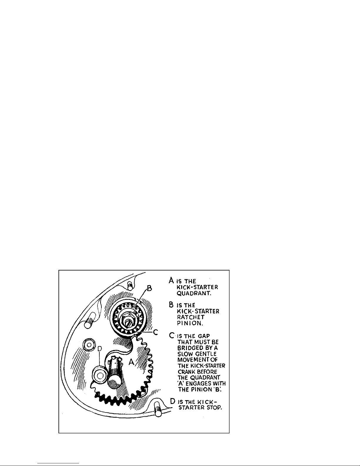
Kick-starterpedal.Thealmostverticalpedalonrighthandsideofgearbox.
FordetailsofuseseePara.5 andIllustration2.
Lightingswitch.Intopofheadlamp.Controlslampsbyrotatingleverwhich
hasthreepositions:—
(1)" OFF."Lampsnoton.
(2)" L."Pilotbulbinheadlampandrearlampon.
(3)" H."Headandrearlampson.Headlamphasa doublefilament.See
Item(17)below.
Ammeter.Intopofheadlamp.Indicatesflowofelectriccurrentin,orout,
ofbattery.("Charge" or" Discharge.")
Hornpushswitch.Depressbuttontosoundhorn.
Gearboxfillercap.SeeParas.23and66.
Footrest.Forrider.
Petroltankfillercap.Torelease,slightlydepress,turn,andthenliftaway.
Oiltankfillercap.OperatedasPetroltankfillercap(15).
Dippingswitch.Triggerswitchonlefthandlebar.Usedtoselectnormalor
"dipped" beamofheadlampwhenmainlightingswitchleverisinthe" H "
position.
2CONTROLS
6

Before using the machine, sit on the saddle and become familiar with the position and
operation of the various controls. Pay particular attention to the gear positions See
Para. 7 and Illustration 3.
Although all the controls are adjustable for position, the only ones that may require
alteration to suit the individual taste of the rider are the foot brake pedal (see Para. 89),
and the gear change foot pedal (see Para. 7). If any adjustment is made to the rear
brake pedal make certain the brake does not bind and also see there is not excessive
free pedal movement before the brake comes ',' on." (See Para. 90).
Illustration1
Showing Controls.
C—M
7

DRIVING
3FUEL
AtthetimeofpublishingthisInstructionBookonlyonegradeofmotorfuelison
sale,butitmaybethatsoonthevariousgradesofpre-warpetrolwillagainbe
available.
Werecommendtheuseonlyofbestqualityfuelbecausethesmallamountofeconomy
thatmightbeconsideredtoaccruebyusingthecheaperfuelsismorethanoffsetby
theadvantagesobtainedbyusingonlyNumberOnegrades.
Whenusinganti-pinkingfuels,ifbyreasonoftravellingslowlyintopgear(suchas
mayoccurunderheavytrafficconditionsorwhenascendinga steephill),theengine
commencestolabour,itisnecessarytochangedowntoa lowergearinorderto
lessonthestrainontheengineandtransmission.A gooddriverisabletosense such
conditionsandwillmakethechangebeforetheenginehasreachedthestageofdistress.
Rememberthegearboxisprovidedtobeusedandfulluseshouldbemadeofthe
lowergearsinordertoobtaineffortlessrunningandhillclimbing.
4FUELSUPPLY
Twopetroltapsaresituatedunderneaththerearendofthepetroltank.(Oneeach
side).Bothmustbeshutoffwhenthemachineisleftstandingformorethana few
minutes.
Thetapplungersworkhorizontally.Toopen,thehexagonknob(marked" Push-On")
ispushedtowardsthebodyofthetap.Toclose,presstheroundmilledknob(marked
"Push-Off").
Normally,onlyusethetapontherighthandsideofthemachineandtheothersidewill
thenactasa reservesupply.Alwaysre-fuelassoonaspossibleafterbeingforcedto
calluponthereserve,andthenatonceclosethe" reserve " tap.
Itwillbenotedthat,byfittingtwopetroltaps,itispossibletoremovethepetroltank
fromthemachinewithoutthenecessityoffirstdrainingitoffuel.
Illustration 2
Kick-starterquadrant
andratchetpinion.
8

5STARTINGTHEENGINE
(a) Seethatthereissufficientfuelinthepetroltank
(b) Seethatthereissufficientoilintheoiltank.
(c) Seethatthegearpedalisintheneutralposition.(SeePara.7).
(d) Pushinwardthehexagonalendofoffsidepetroltapslide.
(e) Seethattheaircontrolleverisinthefullyclosedposition.
(f) Fullyadvancetheignitionandthenslackbackthecontrollevertwo-fifthsofits
totalmovement.
(g) Openthethrottlenotmorethanone-sixthofthetotalmovementofthetwistgrip.
(h) Depresstheplungeronthetopofthecarburetterfloatchamberuntilitcanbe
feltthechamberisfullofpetrol.
(i)Raisethevalvelifterleverand,whilekeepingitraised,turnovertheengineseveral
timesbydepressingthekick-starterpedal,threetimes,theobjectbeingtofree
theengine.(Thisonlyappliesiftheengineiscold.)
(j) Depressthekick-starteruntilcompressionisfelt,thenraisethevalvelifterlever
andeasetheenginejustovercompression.Then,afterallowingthekick-starter
pedaltonearlyreturntoitsnormalposition,giveita longswingingkickwiththe
valveclosedandtheengineshouldimmediatelyfire.
Thekick-startermechanismmustbeallowedtoproperlyengagebeforeputtingheavy
pressureonthekick-startercrankpedalpin.Thatmeanstherearetwodefinite
andseparatemovementswhenoperatingthemechanismbydepressingthecrank.
Thefirstisa slowandgentlemovementwhichendswhenitisfeltthequadranthas
engagedwiththeteethontheratchetpinion.(SeeIllustration2).
Illustration3
Showingtherelative
positionstakenupbythe
movinggearindicator
whenthevariousgearsare
engaged.
Themovinggearindicator
isattachedtothecontrol
spindleandthefixedgear
indicatorislocatedonthe
kick-startercasecover.
Thetwoindicatorsare
onlyinlinewitheach
otherwhenthefootgear
changepedalisinthe
neutralposition.
Thefirstslowandgentlemovementisessentialtoavoiddamagetotheteethofthe
kick-starterquadrant.
Aftertheenginehasstarted,slowlyopentheairleveruntilitrunsevenly.Thenset
thethrottlesothattheengineisrunningata moderatespeed(neitherracingnorticking
over)andallowtowarmup.Whiledoingthis,checktheoilcirculationasdetailedin
Para.12.Themachinecanthenbetakenontheroad.
DON'TS:—
Donotraceuptheenginefromcold.
Donotfloodthecarburettertosuchanextentthatpetrolisdripping,becausethen
intheeventofa backfirethereisa dangerofsuchloosepetroligniting.Thiscannot
possiblyhappenifthestartinginstructionsabovearecarefullyfollowed,butinthe
eventofa firethereisnocauseforpanic.Merelyturnoffthepetroltaptoisolate
themainsupply,openthethrottlewideandturntheengineoveronceortwicewith
thevalvelifterraised,whensuctionwilldotherest.
9

6 STOPPING THE ENGINE
To stop the engine, close the throttle, raise the valve lifter lever and keep it raised
until the engine has ceased to revolve.
7 ON THE ROAD
Having started and warmed up the engine, take the machine off the stand, sit astride it,
free the clutch by pulling up the large lever on the left bar and engage the lowest gear.
Next, slowly release the clutch lever and the machine will commence to move forward.
As it does this, the engine speed will tend to drop as it picks up the load so it will be
necessary to slightly increase the throttle opening, bit by bit, to keep the engine speed
gently rising.
When well under way, disengage the clutch, slightly close the throttle, engage second
gear and release the clutch lever, then open up the throttle to increase the speed of
the machine. Repeat these operations in order to engage third and top gears.
To engage a higher gear the pedal is pressed downward with the toe and a lower gear is
obtained by raising the pedal with the instep. To engage first gear from the neutral
position, the pedal is therefore raised. After each pedal movement, internal springs
return the pedal to its normal horizontal position.
The pedal must be moved to the full extent of its travel when selecting a gear, either
up or down. It must not be " stamped down " or jabbed, but firmly and decisively
moved till it stops. A half-hearted movement may not give full engagement. Keep
the foot off the pedal when driving and between each gear change because, unless the
lever can freely return to its normal central position, the next gear cannot be engaged.
Finally, fully advance the ignition and leave it in that position unless it is necessary to
retard in order to ease the engine and so prevent " pinking " when pulling hard on a
gradient.
8 NOTES ON DRIVING
If, at first, the lowest gear will not engage, release the clutch lever and after a second
or two, make another attempt. This condition may exist in a new machine, but it
tends to disappear after a little use.
Always endeavour to make the movements of hand (on the clutch) and foot (on the
gear pedal) as simultaneous as possible, and remember, in all gear changes a steady
pressure of the foot is desirable. This pressure should be maintained until the clutch
lever is fully released. It is not sufficient to just jab the foot pedal and then release
the clutch lever. When actually in motion, it will be found sufficient to merely free
the clutch a trifle to ease the drive when changing gear and with reasonable care changes
of gear can then be made without a sound.
Do not race the engine unnecessarily or let in the clutch sufficiently suddenly to cause
the rear wheel to spin. Take a pride in making a smooth get-away.
When changing up to a higher gear, as the clutch is freed, the throttle should be slightly
closed so that the engine speed may be reduced to keep in step with the higher gear
ratio. Conversely, when changing down to a lower gear, the throttle is to be regulated
so that the engine speed is increased to keep in step with the lower gear ratio.
Do not slip the clutch to control the road speed.
The clutch must only be used when starting from a standstill and when changing gear.
It must not be operated to ease the engine instead of changing gear, or be held out
in order to "free-wheel."
The exhaust valve may be lifted, when the machine is being slowly ridden, with first
gear engaged, down exceptionally steep, or difficult, gradients to prevent the rear
wheel locking on a loose surface.
10

TheexhaustvalvelifterisNOTusedinnormaldrivingonmainandsecondaryroads.
Whentravellingslowly,suchasmayoccurintrafficorona hill,andtheenginecommences
tolabour,itisthennecessarytochangetoa lowergear.Engine" knocking " or
"pinking" anda harshnessinthetransmissionaresymptomsofsuchlabourandalthough
reliefcansometimesbefoundbyretardingtheignition,itisgenerallymuchbetterto
changedown.A gooddriverisabletosensesuchconditionsandwillmakethechange
beforetheenginehasreachedthestageofdistress.Thegearboxisprovidedtobe
usedandconsequentlyfulluseshouldbemadeoftheintermediategearstoobtain
effortlessrunningandsmoothhillclimbing.
Keepthefeetclearofthebrakeandgearpedalswhennotactuallyusingthemandkeep
thehandofftheclutchleverwhennotisuse.
Driveasmuchaspossibleonthethrottle,makingtheminimumuseofthebrakes.
9STOPPINGTHEMACHINE
Tostopthemachine,closethethrottle,declutchbyliftingthelargeleverontheleft
bar,andgentlyapplybothbrakes,increasingthepressureonthemastheroadspeed
ofthemachinedecreases.Placethegearchangefootpedalintheneutralposition
andstoptheengine.(SeePara.6).
Beforeleavingthemachine,turnoffthefuelsupply,becauseshouldthecarburetter
floodwhiletheengineisstationery,thereisa possibilityofneatfuelenteringthecylinder
viatheinletport.Whenthisoccurs,thereisa riskoffirewhenre-startingandreal
dangerofoildilutionwiththeconsequentriskofengineseizure.
Whenusingthemachineonwetorgreasyroads,itisgenerallybettertoapplyBOTH
brakestogether,becausesuddenorharshapplicationofeitherbrakeonly,undersuch
conditions,mayresultina skid.
Inallconditions,itisadvisabletomakea habitofalwaysusingbothbrakestogether
ratherthantohabituallyusingtherearbrakeandreservingthefrontbrakeforemergency.
10RUNNINGIN
Foratleastthefirst500miles,caretoavoidover-drivingmustbetakenand,underno
circumstancesmusttheenginebedrivenonfullthrottleduringthis" runningin"
period.Aboveall,theenginemustnotbeallowedtoattaina highrateofrevolutions
eitherwhenontheroadorrunningidle.Tobeonthesafeside,thefollowingspeeds
shouldnotbeexceededinthevariousgears: 1st,10m.p.h.; 2nd,15m.p.h.; 3rd,
25m.p.h.; andtop,30m.p.h.
Specialattentionmustbegivenduringtherunninginperiodtosuchdetailsastappet
adjustment,chains,brakes,contactbreakerpoints,wheelbearingsandsteeringhead
bearings,allofwhichtendtobeddowninthefirsthundredmilesorso.Particular
notemustbemadeoftheadjustmentofsteeringheadbearings,which,ifrunina slack
condition,willbequicklyruined.Afterthisbeddingdownprocesshastakenplace,
adjustmentstosuchdetailswillprobablyonlybenecessaryatlengthyintervals.
11AFTERRUNNINGIN
Afterthefirst500milesofrunning,speedonthevariousgearsmaysafelybegradually
increased,butundernocircumstancesshouldtheenginebedrivenatmaximum
poweroutputuntilatleast2,000mileshavebeencovered.Althoughtheengineis
capableof" revving"veryfast,over-revvingmust,atalltimes,beavoided,particularly
onthelowergears.
11

Illustration4
Showingtheoiltankwiththefeltfilterin
itscylindricalhousingandthemetalstrainer
mountedontheentryendofthefeedpipe
union.Alsoshowsthedirectionofflowof
oilfromtanktoengineandreturnflowfrom
enginetotankviathesmallspout,located
sothatitcanbeinspectedbyremovingthe
tankfillercap(mentionedinPara.12).
12CHECKINGOILCIRCULATION
Provisionismadetoobservetheoilincirculationanditisnecessarytodothisbefore
eachrun.
Ifthefillercapontheoiltankisremoved,thereturningoilcanbeseenrunningfrom
thesmallspoutjustinsidethefillercaporifice.Thischeckshouldbemadeimmediately
afterstartingtheenginefromcold.Thisisbecausewhiletheengineisstationary,oil
fromallpartsoftheinterioroftheenginedrains,backintothecrankcasesump,sothat,
untilthissurplusiscleared,thereturnflowisverypositiveandcontinuous.Therefore,
iftheoilcirculationisderanged,thefactisapparentatoncebythelackofa steady
returnflow.
Itshouldberememberedthatnormallythereturnflowissomewhatspasmodicand
mixedwithairbubbles.Thisispartlyduetothefactthatthereturnportionofthe
oilpumpplungerhasgreater pumpingcapacitythanthatdeliveringfreshoil,andpartly
duetothevariationsintheamountofoilinsuspenseinthecrankcaseaccordingtothe
enginespeed.Forexample,upona suddenacceleration,thereturnflowmaycompletely
ceasefora time,only,ofcourse,upondeceleration,toresumeata greater ratethan
normal.
13PILLIONPASSENGERS
Theadditionofweighttotherearofa motorcyclemayaffectitssteering.Therefore
theridermustmakesomeallowanceforthedifferenceinthe"feel" ofthemachine
whena passengeriscarried.
Thereartyrepressuremustbeincreasedtosatisfactorilycarryanyincreasedload.
(SeePara.97).
12

LUBRICATION
14LUBRICANTSTOUSE
EfficientIubricationisofvitalimportanceanditisfalseeconomytousecheapoilsand
greases.
Werecommendthefollowinglubricantsforuseinmachinesofourmake:—
FORENGINELUBRICATIONINSUMMER:
Castrol"GrandPrix"
TripleShell
Mobiloil" D "
Essolube" Racer"
Motorine" B deLuxe"
FORENGINELUBRICATIONINWINTER:
Castrol" XXL"
DoubleShell
Mobiloil" BB"
Essolube" Racer"
Motorine" C "
FORGEARBOXLUBRICATION:
EngineOil(SummerGradeasabove).
FORHUBLUBRICATIONANDALLFRAMEPARTSUSINGGREASE:
Castrolease" Medium"
Shell" Retinax" GreaseCD.
MobilgreaseNo.2
EssoGrease
Belmoline" C "
FORTELEDRAULICFRONTFORKS:
Castrolite
SingleShell
Mobiloil"Arctic
Essolube20
Motorine" E "
FORREARCHAINS:
Tallow
WhenbuyingoilsandgreasesitisadvisabletospecifytheBrandaswellasthegrade
and,asanadditionalprecaution,toonlybuyinsealedcontainersorfrombranded
cabinets.
13

15FILLINGTHEGREASEGUN
Thestandardgreasegunconsistsofa barrelhavinga springloadedendcap,towhich
isfixeda centresteelpistonintheshapeofa longrod.Thispistonfitsintoa small
cylindermadeinonewiththescrewedtopcap,ontheendofwhichisthecuppednozzle
thatfitsoverthegreasenipples.Inthebarrelofthegun,andslidingonthecentral
pistonrod,isa corkpiston.
ThegreasemustbefilledontheTOPofthecorkpiston.Thegunmaybefilledby
insertingthegreaseinthebarrelofthegunbymeansofa lathorsimilar"spoon."
However,itisbettertoobtainthegreasepackedinthespecialcontainersthatare
supplied,havingloosecollarsinwhichareholessothat,byplacingthebarrelofthe
gunovertheholeinthecentralfloatingplateand.pressingdownwards,thegunis
instantlychargedwithgrease.Twistingthegun,and,atthesametime,takingitaway
fromthefloatingplate,leavesthetopofthegunbarrelflushwithgrease,andthenall
thatremainstobedoneistoreplacethescrewedtopcap.
Illustration5
EngineOilCirculation.
14

16 ENGINE LUBRICATION SYSTEM
This is by dry sump system. Oil feeds, by gravity, from the oil tank to the pump in the
crankcase. The pump forces oil to various parts, which then drains to the bottom of
crankcase sump. The pump then returns oil to the tank. This process is continuous
while the engine is revolving. The pump is designed to return more oil to the tank
than it can force into the engine. Therefore the crankcase sump is kept clearof excess oil.
A felt cartridge filter, in the oil tank, removes foreign matter collected by the oil in its
passage through the engine. A metal gauze strainer is fitted to the oil feed pipe in the
oil tank to prevent pieces of fluff, etc., which may find their way into the tank when
replenishing, from entering the oil pump. (See Illustration 4).
Felt filter and metal strainer should be cleaned in petrol each time the oil tank is drained.
17 ENGINE OIL PUMP
The pump has only one moving part. This is the plunger which revolves and reciprocates.
Rotation is caused by the worm gear on the timing side flywheel axle. Reciprocation
is caused by the guide pin which engages in the profiled groove cut on the plunger.
Oil is fed to the pump through the lower of the two oil pipes between tank and crank-
case and is returned through the upper pipe.
If, for any reason, the crankcase halves are separated, the oil pump plunger must
be removed from its housing before attempting to separate the crankcase
halves. (See Para. 52.)
18 ENGINE OIL CIRCULATION
The oil pump forces oil through :—
(a) A passage cutthrough the timing side flywheel axle, timing side flywheel and crank
pin to lubricate the big-end bearing. The splash passes to interior of cylinder, to
lubricate the cylinder and piston, and then falls into the crankcase sump.
(b) A passage in crankcase, controlled by ball valve, direct to the cylinder, to assist in
cylinder and piston lubrication and then falls into the crankcase sump.
(c) A passage in timing gear case where it " builds up " to a predetermined level to
lubricate the timing gears and then falls into the crankcase sump.
(d) Through a pipe from the front of oil pump housing to the rocker box by which
all rocker gear and valve stem"! are lubricated and then falls through the push rod
cover tubes and tappet guides to the timing gear case and, from there, drains into
the crankcase sump, as detailed in Para. (c).
The oil pump extracts oil in the crankcase sump and returns it to oil tank. On its way
it passes through the felt cartridge filter located in the oil tank.
19 THE OIL TANK AND FILTERS
The level of oil in the tank should never be less than about half-full (otherwise the small
amount of oil becomes excessively hot and dirty, thereby impairing lubrication and
cooling), or more than within one inch of filler cap opening (otherwise, upon starting
the engine, the bulk of oil then in the crankcase sump may be greater than the space
left in the oil tank.
The oil filter is made in cylindrical form of thick felt and is supported by a tubular wire
cage. The felt is not detachable from the cage.
A metal gauze strainer (secured to the feed pipe union) stands in the oil tank.
Subsequent to the renewal of oil at 500 and 1,000 miles it should be changed every
five thousand miles. When oil is changed, both felt filter and metal strainer should be
removed and cleaned in petrol.
D—M
15

Foraccesstooilfilter:—
Unscrewthehexagonalheadedcapontopofoiltankandwithdrawthedishedwasher
andspring.Theninserta fingerinthefeltfilterandgentlyraisesameuntilthe
topendtouchestheunderneathofsaddle.Thenbyencirclingthefilterwiththehandit
willbefoundpossibletoexertsufficientupwardpressureontheflexiblesaddletopto
permitthefiltertobecompletelywithdrawnwithoutdistortion.Careisneededto
avoidkinkingthefilter.
Tore-fitfilter:—
Reverseaboveinstructions.
Note:—
If,afterthefilterhasbeenremovedfromthetank,itisdamaged,sothatthe
feltisperforated,ortheendsdistorted,itisessentialtodiscarditandtofita
newfilter.
Becarefultoavoiddamagingthefilterdrthecorkwasherunderthehexagonal
cap.
Foraccesstometalstrainer(afteroilhasbeendrainedfromtank):—
Removeoilfeedpipefromunionscrewedintobottomofoiltank.Thisispipe
nearertorearwheelandisremovedbyunscrewingitsunionnut.
Springawaypipefromunion.
Unscrewunionfrombottomofoiltank.Metalstrainerisintegralpartofthis
union.
Tore-fitmetalstrainer:—
Reverseaboveinstructions.
20ADJUSTMENTOFOILFEED
Theinternalflowofoilisregulatedbyfixedrestrictions.Noadjustmentisprovided
exceptfortheoilfeedtotheinletvalvestem.Thisadjustmentismadebya needle
pointedscrewlocatedintherightsideofcylinderhead.(SeeIllustration6).Itis
lockedinpositionbya nut.Theapproximatecorrectsettingisonesixthofa complete
turnfromthefullyclosedposition.Oncesetitrequireslittle,orno,adjustment.
Inletvalvesqueakindicatestheoilfeedadjustmentisnotopenenough.Excessiveoil
consumption,a smokyexhaustoranoiledsparkingplug,generallyindicatestheoil
feedadjustmentisopentoomuch.
21EXHAUSTVALVESTEMLUBRICATION
Theexhaustvalvestemislubricatedbyoilfedthrougha passagedrilledinthecylinder
head.Noadjustmentisprovided.Allexcessoilisby-passedbacktothetiminggear
case.
22LUBRICATIONPOINTSTOREMEMBER
Adirty,orchoked,feltoilfiltercausesheavyoilconsumption.Thisisbecausethe
returnflowofoiltotheoiltankisslowed,orevenalmostcompletelystopped,thereby
allowinganexcessofoilto" buildup" inthecrankcasesump,muchofwhichpasses
tothepiston.
Acloggedmetalstrainer,inthegravityfeedpipe,willalsocauseimproper,orno,oil
circulation.Thiscanonlyoccurastheresultofaddingdirtyoilwhenreplenishingthe
tank.
Bothendcapsonpumpplungerhousingmustbeair-tight.
Checkoilcirculationbeforestartingeachrun.
16

Illustration6
Theinlet valveguideisshownwithdrawnasalsoistheinletvalvestem
adjustingscrew(withlocknut).
(By courtesy of " Motor Cycling ")
1
2
3
4
S
6
7
8
9
PLAINHOLE,TOACCOMMODATECYLIN-
DERHEADRETAININGBOLT.
GUIDE,FORVALVE.
CYLINDERHEAD.
TAPPEDHOLE,TOACCOMMODATE
ROCKERBOXRETAININGBOLT.
PLAINHOLE,TOACCOMMODATEVALVE
GUIDE.
TAPPEDHOLE,TOACCOMMODATE
CARBURETTERRETAININGSTUD.
INLETPORT.
TAPPEDHOLE,TOACCOMMODATE
CARBURETTERRETAININGSTUD.
PLAINHOLE,TOACCOMMODATECYLIN-
DERHEADRETAININGBOLT.
10
II
12
13
14
15
16
TAPPEDHOLE,TOACCOMMODATE
NEEDLESCREW.
NEEDLESCREW,ADJUSTINGOILFEED
TOINLETVALVE.
LOCKNUT,FORNEEDLEADJUSTING
SCREW.
PLAINHOLE,FOROILFEEDTOINLET
VALVE.
PLAINHOLE,TOACCOMMODATEPUSH
RODCOVERTUBETOPGASKET.
PLAINHOLE,FOROILFEEDTOEXHAUST
VALVE.
TAPPEDHOLE,FORSPARKINGPLUG.
17

23 GEAR BOX LUBRICATION
The gear box must not be entirely filled with oil, and, under normal conditions,
the addition of about two ounces of oil every 1,000 miles will be sufficient.
Excessive oil will cause leakage. (Correct content 20 fluid ozs. (1 pint) 568 c.c).
In no circumstances must heavy grease be used for gear box lubrication. See para. 14.
Lubricant may be inserted through grease nipple on the kick-starter case or through
the filler cap orifice.
A screwed drain plug in gear box shell (low down at rear) facilitates gear box flushing
and change of lubricant.
24 CHAIN LUBRICATION
Front driving chain and dynamo chain run in oil bath. (Front chaincase.) Use engine
oil. Maintain level to height of the inspection cap opening.
Oil in front chaincase also lubricates the engine shock absorber. Transmission harshness
generally indicates level of oil in chaincase is too low.
Remove chaincase inspection cap each week, inspect level of oil, top-up as necessary.
To remove inspection cap :—
Unscrew knurled screw about four turns.
Slide cap sideways, till the back plate can be slipped through the opening, and
take away the complete cap assembly.
When replacing inspection cap, centralise cork washer and then fully tighten
knurled screw. Essential this is kept tight otherwise cap assembly will be lost.
Rear driving chain should be removed for lubrication. Clean chain in paraffin, drain
and wipe. Immerse in bath of molten tallow, leave for several minutes, remove and
allow excess lubricant to drain off and then replace on machine. Engine oil is a poor
substitute for tallow and, if used, chain should be allowed to soak for several hours.
Lubricate rear chain every two thousand miles in Summer and every thousand miles in
Winter.
Magneto chain runs in case packed with grease. A grease nipple is fitted to the case
cover. Inject small quantity of grease every thousand miles.
25 HUB LUBRICATION
Keep hubs packed with grease. This prevents entry of water and dirt. Nipples in
centre of hubs. Inject small quantity of grease. Excessive grease may reach brakes
and impair their efficiency.
26 BRAKE EXPANDER LUBRICATION
Nipple on each brake expander bush. (One on front brake cover plate, one on rear
brake cover plate.) Use grease very sparingly. Excessive grease may impair efficiency
of brake.
27 BRAKE ROD JOINT LUBRICATION
A few drops of engine oil on each brake rod yoke end pin and on the threaded rear
portion of brake rod. (One yoke end pin at each end of brake rod and one at bottom
end of front brake cable).
18
Other manuals for 1949 CLUBMAN G3L
1
This manual suits for next models
1
Table of contents
Other Matchless Motorcycle manuals