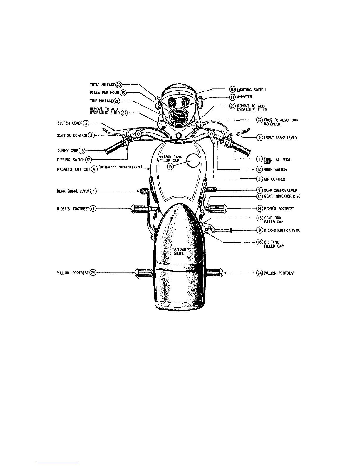
Matchless 1949 CLUBMAN G3L User manual

MAINTENANCE
MANUAL
AND
INSTRUCTION
BOOK
1955
350c.c.and500c.c.
for
MATCHLESS
SPRING FRAME AND RIGID
SINGLE CYLINDER MODELS
PRICE 2/6 NETT
MATCHLESS
M O T O R C Y C L E S
PROPRIETORS : ASSOCIATED MOTOR CYCLES LIMITED
PLUMSTEAD • LONDON • S.E.18


for
1955
SINGLE CYLINDER MOTOR CYCLES
Compiled and Issued by the Manufacturers :
MATCHLESS MOTOR CYCLES
(Proprietors : ASSOCIATED MOTOR CYCLES LIMITED)
Registered Offices :
PLUMSTEAD ROAD, PLUMSTEAD
LONDON, S.E.18 .. ENGLAND
Nearest Station :
WOOLWICH ARSENAL
(Southern Region Railway)
Factories :
BURRAGE GROVE and MAXEY ROAD
PLUMSTEAD. S.E.18
Telegrams and Cables : "MATCHLESS, WOL-LONDON"
Telephone : WOOLwich 1 2 2 3 (7 Lines)
Codes : A.B.C. 5th and 6th Edition ; Bentley's ; and Private Codes
All correspondence to :
MATCHLESS MOTOR CYCLES, PLUMSTEAD ROAD, LONDON. S.E.18
Price: TWO SHILLINGS and SIXPENCE
A—S
MAIN TENANCE MANUAL
AND INSTRUCTION BOOK

1955MATCHLESSMODELS
350MODELG3LRIGIDFRAME(TOURING)
350MODELG3LSSPRINGFRAME(TOURING)
350MODELG3LCRIGIDFRAME(COMPETITION)
350MODELG3LCSSPRINGFRAME(COMPETITION)
500MODELG80RIGIDFRAME(TOURING)
500MODELG80SSPRINGFRAME(TOURING)
500MODELG80CRIGIDFRAME(COMPETITION)
500MODELG80CSSPRINGFRAME(COMPETITION)
G3LandG80RigidFrame
G3LSandG80SSpringFrame

INTRODUCTION
Themodernmotorcycleunquestionablyprovidesoneofthemosthealthy,
economicalandpleasantmeansoftransport.Inadditionbyreasonofits
superbbraking,highpowertoweightratioandeaseofcontrolitis,ifused
withduecareoneofthesafestvehiclesontheroad.
Itisoursinceredesirethateveryownershouldobtainfromhismount
theservice,comfortandinnumerablemilesoflowcosttravelthatwehave
earnestlyendeavouredtobuildintoit.
Itmustbeborneinmindhowever,thatalthoughofsimpledesignand
construction,itisneverthelessa highlyspecialisedpieceOfengineering
andmustinconsequencebeintelligentlyandefficientlymaintainedin
ordertoprovideunfailingreliability.
Inthisbookweprovidenon-technicalinstructionsforcarryingoutallthe
maintenanceoperationslikelytobecalledforinnormalservice,'together
withassistingillustrations.
Toownersoflongexperiencewetenderapologiesfortheelementary
natureofsomeofthecontentsofthishandbook,butownerswhether
noviceorexpertareadvisedtoreadthecontentsfrombeginningtoend.
Weareatalltimespleasedtogiveownersthefullbenefitofourwide
experienceinmattersrelatingtomotorcyclesofourmanufactureand
elsewherewillbefounddetailsoftheparticularsrequiredwhenmaking
enquiriesofourServiceDepartment.
ASSOCIATEDMOTORCYCLES
Safety on the Road
Intheinterest ofSafetyontheRoada fewwordsofwarningareperhapsnotoutof
placehere.
Theoutstandingmanoeuverabilityofa motorcycleoverallothervehiclesontheroad
makesitnecessarytoexercisecautionatalltimes.
Thereareunfortunatelya fewmotor-cyclistswhoserecklessdrivingconstitutesa
menacenotonlytothemselvesbutalsotootherroadusersresultinginthetotallyfalse
impressioninsomequartersthatmotorcyclingisa dangerouspastime.
Takea prideinyourridingtechniqueandneverrelyupontheotherfellowdoingthe
rightthing.
Yourexampleofcareful,courteousandunobtrusiveridingwillmateriallycontributeto
roadsafetyandtothereputationofa finesportingpastime.
B—S.
3

DATA
Engine Number Stamped on left hand side of crankcase
frame Number Stamped on seat lug of main frame, on right hand side (below the saddle
Bore 350 c.c. Models—2·7187 in. (2Fin.)
500 c.c. Models—3250 in. (3¼in.)
Stroke
All Models—93 mm. (3·5625in.)
Engine capacity, in cubic centimetes 350 Models—55/16M, 55/16MS, 55/16MC and 55/16MCS—347
500 Models—55/18, 55/18S, 55/18C and 55/18CS—498
Capacities
Location British Metric
Engine 350 c.c.
Engine 500 c.c.
Gear box
Front fork (each side)
Rear leg (each leg)*
Rear wheel fork hinge bearing*
Fuel Tank (all except Competition)
Fuel tank (Competition)
Oil tank (to top level mark)
*On Spring Frame Models only.
21·170 cub. in.
30-380 cub. in.
1 pint
6½
fl.
ozs.
3 fl. ozs.
1½
fl.
ozs.
3¾gallons
2¼gallons
4½pints
347 c.c.
498 c.c.
568·2 c.c.
184·6 c.c.
85 c.c.
42·6 c.c.
17·04 litres
10·2285 litres
2·557 litres
Carburetter (Touring and Rigid Frame Competition Models only)
Type
Main jet
Pilot jet
Throttle valve
Choke size
Needle position
Needle jet
350
c.c.
Monobloc 376/5
376/100 size 210
376/076 size 30
376/060 size 3
1·1/16"
Central notch
376/072 size ·1065
500 c.c.
Monobloc 389/1
376/100 size 260
376/076 size 30
389/060 size 3
1·5/32"
Central notch
376/072 size ·1065
NOTE—
Early 1955 Models 500 c.c. up to Engine No. 27,000 are fitted with type Monobloc 376/14 carburetters
with main jet size 240, throttle valve 376/060 size 3 and needle position 2nd notch from top.
All Spring Frame Competition Models are fitted with T.T. type carburetters.
Compression ratios
Model
350
500
Normal
ratio
6·53 to 1
6·26 to 1
High
ratio
According to piston.
See Spares List for
ratios available.
… … … … … … … …
… … … … … … … … …
… … … … … … … … …
… … …
… … … … …
… … … … …
… … … …
… … … …
… … … …
… … …
… … …
… … … … … …
… …
… … … … … … … …
…………………
…………………
…………………
…………………
…………………
………………
4

Model
Touring
Competition (Rigid)
Competition (Spring)
First gear
2·65 to 1
3·199 to 1
2·65 to 1
Second gear
1·70 to1
2·437 to 1
1·70 to
1
Third gear
1·308 to 1
1·575 to 1
1·308 to 1
Fourth gear (top)
1
to 1
1
to 1
1
to 1
Gear box ratios
Gear ratios, Touring (Rigid and Spring Frame) and Spring Frame Competition
Models
Engine sprocket size
15 teeth
(c) 16 teeth
17 teach
(a) 18 teeth
19 teeth
20 teeth
21 teeth
First gear
18·55 to 1
17·32 to 1
16·32 to 1
15·44 to 1
14·55 to 1
13·91 to 1
13·25 to 1
Second gear
11·90 to
1
11·15 to 1
10·47 to 1
9·90 to 1
9·33 to 1
8·91 to 1
8·50 to 1
Third gear
9·15 to 1
8·58 to 1
8·05 to 1
7·63 to 1
7·18 to
1
6·86 to 1
6·54 to 1
Fourth gear
(top)
7 to 1
6·56 to 1
6·16 to 1
5·83 to 1
5·49 to 1
5·25 to 1
5·0 to 1
(a) Standard (or 350 c.c. Touring Models and 500 c.c. Spring Frame Competition Models.
(b) Standard for 500 c.c. Touring Models.
(c) Standard for 350 c.c. Spring Frame Competition Models.
Gear ratios, Competition Rigid Frame Models
Engine sprocket size
15 teeth
(a) 16 teeth
17 teeth
18 teeth
19 teeth
20 teeth
21 teeth
First gear
22·4 to 1
21·0
to 1
19·7 to
1
18·68 to 1
17·57 to 1
16·8 to
1
16·0 to
1
Second gear
17·25 to 1
15·98 to 1
15·0 to 1
14·2 to 1
13·38 to 1
12·8 to
1
12·18 to
1
Third gear
11·03 to 1
10·33 to 1
9·7 to
1
9·2 to
1
8·65 to 1
8·37 to 1
7·81 to 1
Fourth gear
(top)
7 to 1
6·56 to 1
6·16 to
1
5·83 to 1
5·49 to 1
5·25 to 1
5·0 to 1
(a) Standard for 350 c.c. Models.
(b) Standard for 500 c.c. Models.
Ignition (magneto)
Model
Touring 350 c.c.
Touring 500 c.c.
All Competition
Make
Lucas
Lucas
Lucas
Type
SR-1
SR-1
NR-1
Rotation
Anti-clock
Anti-clock
Anti-clock
Point gap
·012 in.
·012 in.
·012 in.
Ignition point before top
dead centre (with control
in fully advanced position)
Normal 39°—½"
Normal 39°—½"
Normal 39°—½"
Lighting (bulbs)
Location.
Head lamp (Pre-focus)
Pilot lamps
Rear lamp
Speedometer
Type
Double filament
Single contact
Double filament
Single contact
Voltage
6
6
6
6
Wattage
30x24
3
18& 3
1·8
Part
number
312
988
352
53205
(b)
(b)
… … …
… … …
… … …
… … …
… … …
… … …
… … …
… … …
… …
…
… … …
… … …
… … …
… … …
… … …
… … …
… … …
… … …
… … …
… … …
… … …
… … …
… …
… …
…
5

Oversize parts
The following are the only " oversize " variations provided for the 350 and 500 c.c. Single Cylinder machines.
Big-end rollers :
·001 in. oversize
Cylinder re-bore :
·020 in. and ·040 in. oversize
Pistons and rings :
·020 in. and ·040 in. oversize
Pistons (standard size)
Model Top of skirt diameter
350 2·7176 in.
500 3·2490 in.
Front to rear clearance
·001 in.
·001 in.
Part number
013504
013505
All above measurements are subject to a toleration limit of + or — ·0005 in.
Piston rings
Piston ring gap—Normal
Permissible maximum
Piston ring clearance in groove
·006 in.
·030 in.
·002 in.
Sparking Plug
Model
All
Make
K.L.G.
Type
FE80
Thread
14 mm.
Reach
¾ in.
Point gap
·020 to ·022 in.
Valve timing
All timing gears are marked for ease of setting. (See Illustration 10)
With Marks coinciding correct timing is assured.
Valve Guide Projection (Top of Guide to Boss)
Inlet—½" Exhaust—½"
Valve timing pinion
Retained by nut, threaded vin. by 26 threads per in. Left hand thread Part number 000221.
Weight
Model
350
500
Standard
Rigid frame
344 lbs.
353 lbs.
Spring frame
375 lbs.
386 lbs.
Competition
Rigid frame
300 lbs.
303 lbs.
Weight of machine with empty tanks
Wheels (bearing end play)
Bearing end play ·002 in. (just a perceptible rim rock).
… … … … … … … … …
… … … … … … … …
… … … … … … … … …
…
… …
… …
… …
… … …
… … …
… … …
6

CONTROLS
(1) Throttle twist grip. On right handlebar. Twist inwards to open. When
fully closed engine should just Idle when hot.
(2) Air lever. Small lever on right handlebar. Pull Inwards to increase air supply
to carburetter. Once set, when engine has warmed up, requires no alteration
for different road speeds. Should be fully closed when starting engine from cold.
(3) Ignition lever. When fitted, Small lever on left handlebar. Advances and
retards ignition point. Pull inwards to retard. Retard two-fifths of total
movement for starting. (Only used on Competition Models).
(4) Valve lifter lever. Small lever close to clutch lever. Lifts exhaust valve from
seat, releasing compression in combustion chamber, enabling engine to be easily
rotated for starting. Also used for stopping engine if throttle stop is set as
advised above.
(5) Clutch lever. Large lever on left handlebar. Grip to release clutch so that
drive to rear wheel is disconnected.
(6) Front brake lever. Large lever on right handlebar. Grip to operate front
wheel brake and, for normalbraking, use in conjunction with rear brake application.
(7) Rear brake lever. Pedal close to left side foot rest. Depress with left foot to
apply rear brake. Apply gently and use increasing pressure as the road speed
decreases.
(8) Gear change lever. Pedal in horizontal position close to right foot rest. Con-
trols selection of the four speeds, or ratios, between engine and rear wheel
revolutions, with a " free," or neutral, position. See illustration 2.
(9) Kick-starter lever. Vertical pedal on right hand side of gear box.
(10) Lighting switch. In top of head lamp. Controls lamps by a rotating lever which
has three positions :
(1) " OFF " Lamps not on.
(2) " L " Pilot lamps, rear lamp and speedometer lamp on.
(3) " H " Main head lamp, rear lamp and speedometer lamp on.
(11) Ammeter. In top of head lamp. Indicates flow of electric current, in, or out,
of battery. (" Charge " or " Discharge.")
(12) Horn switch. Press switch on right handlebar.
(13) Gear box filler cap. Located on top edge of kick-starter case cover. Allows
Insertion of lubricant and access to clutch Inner wire and internal clutch operating
lever.
(14) Footrest for rider.
(15) Petrol tank filler cap. Located in top of fuel tank. To release, slightly depress,
turn fully to the left, and then lift away. There are two locking positions. The
middle position, between the fully tightened down and " lift away " positions,
is in the nature of a " safety " device to prevent loss that might be occasioned by
unauthorised meddling.
(16) Oil tank filler cap. Located on top edge of oil tank. The construction and
operation is exactly as the petrol tank filler cap.
(17) Dipping switch. Trigger switch on left handlebar. Used to select normal or
" dipped " beam of head lamp when main lighting switch lever is in the " H "
position. (The main head lamp bulb has two filaments.)
C—S.
7

If any adjustment is made to the rear brake pedal make certain the brake does not bind
and also see there is not excessive free pedal movement before the brake comes " on. "
Illustration 1
Showing Controls
Before using the machine, sit on the saddle and become familiar with the position and
operation of the various controls. Pay particular attention to the gear positions.
8

DRIVING
FUEL
Althoughvariousqualityfuelsareagainavailableownersareadvisedtouseonlythe
best.Thesmalleconomythatmightbeconsideredtoaccruebyusingthecheaper
gradesismorethanoffsetbytheadvantagesobtainedbyusingonlyNumberOne
Grades.
FUELSUPPLY
Twofuelfeedtapsaresituatedunderneaththerearendofthepetroltank.(Oneeach
side.)Bothmustbeshutoffwhenthemachineisleftstandingformorethana few
minutes.
Thetap plungersworkhorizontally.Toopen,pullplungerout.Pushrightintoclose.
Normally,onlyusethetapontherighthandsideofthemachineandthentheother
sidewillactasa reservesupply.Alwaysre-fuelassoonaspossibleafterbeingforced
to calluponthereserve(approx.½gallon),andthen,at once,closethe" reserve" tap.
Itwillbenotedthat,byfittingtwopetrolfeedtaps,itispossibletoremovethepetrol
tankfromthemachinewithoutthenecessityof firstdrainingit of fuel.
STARTINGTHEENGINEFROMCOLD
(a) Seethatthereissufficientfuelinthepetroltank.
(b) SeethatthereIssufficientoilIntheoiltank.
(c) SeethatthegearpedalisIntheneutralposition.
(d) Pulloutwardtheplungerofoff-sidepetroltap.
(e) SeethattheaircontrolleverisInthefullyclosedposition.
(f) Openthethrottlenotmorethanone-sixthofthetotalmovementofthetwistgrip.
(g) DepresstheplungeronthetopofthecarburetterfloatchamberuntilItcanbe
feltthechamberIsfullofpetrol.
(h) Raisethevalvelifterleverand,whilekeepingitraised,turnovertheengineseveral
timesbydepressingthekick-starterpedal,threetimes,theobjectbeingtofree
theengine.(Thisonlyappliesiftheengineitcold.)
(i) Depressthekick-starteruntilcompressionisfelt,thenraisethevalvelifterlever
andeasetheenginejustovercompression.Then,afterallowingthekick-starter
pedaltoreturnnearlytoitsnormalposition,giveita longswingingkickwiththe
valveclosed.Flywheelmomentumwillcarryovercompressionandtheengine
shouldfireimmediately.Ifitfailstodosorepeatexactlythesameprocess.
Donotallowkickstartertoreturnviolentlyagainstitsstop.
Thekick-startermechanismmustbeallowedtoengageproperlybeforeputtingheavy
pressureonthekick-startercrankpedalpin.Thatmeanstherearetwodefinite
andseparatemovementswhenoperatingthemechanismbydepressingthecrank.
ThefirstIsa slowandgentlemovementwhichendswhenitisfeltthequadranthas
engagedwiththeteethontheratchetpinion.
9

Illustration2
Showingthegearindi-
catordrumwhichupon
assemblyissettorecord
thevariousgearsand
neutralposition,asthe
respectivefigure orletter
Nregisterswithindex
markonthegearboxshell.
Uponre-asembly,after
dismantlingforanypur-
pose,theindexdiscshould
becorrectlyre-setfor
futurereference.
Thefirstslowandgentlemovementisessentialtoavoiddamagetotheteethofthe
kick-starterquadrant.
Aftertheenginehasstarted,slowlyopentheairleveruntilitrunsevenly.Thenset
thethrottlesothattheengineisrunningata moderatespeed(neitherracingnorticking
over)andallowtowarmup.Whiledoingthis,checktheoilcirculationasdetailedin
page13.Themachinecanthenbetakenontheroad.
NOTE—Donotraceuptheenginefromcoldanddonotfloodthecarburettertosuch
anextentthatpetrolisdrippingbecausethen,intheeventofa backfire,there
isa dangerofsuchloosepetroligniting.Thiscannotpossiblyhappenifthe
startinginstructionsarecarefullyfollowed,but,intheeventofa fire,thereis
nocauseforpanic.Merelyturnoffthepetroltaptoisolatethemainsupply,
openwidethethrottleandturnovertheenginebyoperatingthekick-starter
pedalwhensuctionwillextinguishthefire.
STOPPINGTHEENGINE
Tostoptheengine,closethethrottle,raisethevalvelifterleverandkeepitraised
untiltheenginehasceasedtorevolve.
ONTHEROAD
Havingstartedandwarmeduptheengine,takethemachineoffthestand,sitastrideit,
freetheclutchbypullingupthelargeleverontheleftbarandengagethelowestgear.
Next,slowlyreleasetheclutchleverandthemachinewillcommencetomoveforward.
Asitdoesthis,theenginespeedwilltendtodropasitpicksuptheloadsoItwillbe
necessarytoincreasethethrottleopening,gradually,tokeeptheenginespeedgently
rising.
Whenwellunderway.disengagetheclutch,slightlyclosethethrottle,engagesecond
gearandreleasetheclutchlever,thenopenupthethrottletoincreasethespeedof
themachine.Repeattheseoperationsinordertoengagethirdandtopgears.
Toengagea highergearthepedalispresseddownwardwiththetoeanda lowergearIt
obtainedbyraisingthepedalwiththeinstep.Toengagefirstgearfromtheneutral
position,thepedalisthereforeraised.Aftereachpedalmovement,internalsprings
returnthepedaltoitsnormalhorizontalposition.
Thepedalmustbemovedtothefullextentofitstravelwhenselectinga gear,either
upordown.Itmustnotbe" stampeddown" orjabbed,butfirmlyanddecisively
movedtillitstops.A half-heartedmovementmaynotgivefullengagement.Keep
thefootoffthepedalwhendrivingandbetweeneachgearchangebecause,unlessthe
levercanfreelyreturntoitsnormalcentralposition,thenextgearcannotbeengaged.
10

STOPPINGTHEMACHINE
Tostopthemachine,closethethrottle,declutchbyliftingthelargeleverontheleft
handlebar,andgentlyapplybothbrakes, increasingthepressureonthemastheroad
speedofthemachinedecreases.Placethegearchangefootpedalintheneutralposition
andstoptheengine.
Beforeleavingthemachine,turnoffthefuelsupply.
IMPORTANTNOTICE
NEVERDRIVEAWAYATHIGHSPEEDWHENSTARTINGA RUNWITHA
COLDENGINE.GIVETHEOILA CHANCETOWARMUPANDTHINOUT.
PARTICULARLYWHENTHEMACHINEISCOLD.UNTILTHEOILREACHES
ITSNORMALRUNNINGTEMPERATURETHECIRCULATIONIS
RESTRICTED.SEIZURESCANBEAVOIDEDBYTAKINGTHISSIMPLE
ESSENTIALPRECAUTION.
RUNNINGIN
Althoughitiscustomarytoquote permittedmaximumspeedsonthevariousgears
duringtheperiodofrunningin,thesearereallynoguidetooverdriving,theonlyessential
thingtoavoidbeingtheuseoflargethrottleopening.
Iftheprecautionistakenoflimitingtheuseofthethrottletoaboutone-thirdofIts
openingduringthefirst1,000miles,irrespectiveoftheroadspeed,andwhetheronthe
levelorclimbing,thenecessaryconditionsforrunninginwillhavebeenobserved.
Specialattentionmustbegiven,duringtherunninginperiod,tosuchdetailsasvalve
rockeradjustment,chains,brakes, contactbreakerpoints,andsteeringheadbearings,
allofwhichtendtobeddowninthefirsthundredmilesorso.Particularnotemustbe
madeoftheadjustmentofsteeringheadbearings,which,ifrunina slackcondition,wilt
bequicklyruined.Afterthisbeddingdownprocesshastakenplace,adjustmentsto
suchdetailswillonlybenecessaryatlengthyintervals.
Afterabout1,000mileshavebeencoveredlargerthrottleopeningsmaybegradually
Indulgedinforshortburstsonly.
Untilatleast2,000mileshavebeencoveredtheownerofa newmachineisstrongly
advisedtocurbhisnaturaldesiretolearnthemount'smaximumcapabilities.Restraint
Inthisdirectionwillbeamplyrepaidlater.
11

NOTESONDRIVING
If,atfirst,thelowestgearwillnotengage,releasetheclutchleverandaftera secondor
two,makeanotherattempt.Thisconditionmayexistina newmachine,butittendsto
disappearaftera littleuse.
Alwaysendeavourtomakethemovementsofhand(ontheclutch)andfoot(onthegear
pedal)assimultaneousaspossible,andremember,inall gearchanges,a steadypressure
ofthefootisdesirable.Thispressureshouldbemaintaineduntiltheclutchisfully
released.Itisnotsufficientjusttojabthefootpedalandthenreleasetheclutchlever.
Whenactuallyinmotion,itwillbefound sufficienttomerelyfreetheclutcha trifle,
toeasethedrivewhenchanginggearand,withreasonablecare,changesofgearthen
canbemadewithouta sound.
DonotunnecessarilyracetheengineorletIntheclutchsufficientlysuddenlytocause
therearwheeltospin.Takea prideinmakinga smooth,silentget-away.
Whenchanginguptoa highergear,astheclutchisfreed,thethrottleshouldbeslightly
closedsothattheenginespeedisreducedtokeepinstepwiththehighergearratio.
Conversely,whenchangingdowntoa lowergear,thethrottleshouldberegulatedso
thattheenginespeedisincreasedtokeepinstepwiththelowergearratio.
Donotsliptheclutchtocontroltheroadspeed.
Theclutchisintendedtobeusedonlywhenstartingfroma standstillandwhenchanging
gear.ItmustNOTbeoperatedtoeasetheengine,insteadofchanginggear,orbeheld
out,inorderto" free-wheel."
TheexhaustvalvelifterisNOTusedinnormaldrivingonmainandsecondaryroads.
Whentravellingslowly,suchasmayoccurintrafficorona hill,andtheenginecommences
tolabour,itisthennecessarytochangetoa lowergear.Engine" knocking" or
"pinking" anda harshnessinthetransmissionaresymptomsofsuchlabour.A good
driverisabletosensesuchconditionsandwillmakethechangebeforetheenginehas
reachedthestageofdistress.Thegearboxisprovidedtobeusedandconsequently
fulluseshouldbemadeoftheintermediategearstoobtaineffortlessrunningandsmooth
hillclimbing.
Keepthefeetclearofthebrakeandgearpedalswhennotactuallyusingthem andkeep
thehandofftheclutchleverwhennotinuse.
Driveasmuchaspossibleonthethrottle,makingtheminimumuseofthebrakes.
Whenusingthemachineonwetorgreasyroads,ItisgenerallybettertoapplyBOTH
brakestogether,becausesuddenorharshapplicationofeitherbrakeonly,undersuch
conditions,mayresultina skid.
Inall conditions,Itisadvisabletomakea habitofalwaysusingbothbrakestogether
ratherthanhabituallyusingtherearbrakeandreservingthefrontbrakeforemergency.
12

REMOVE CAP SPRING AND
DISHED SEAT FOR SPRING,
TO OBTAIN ACCESS TO
FELT FILTER FOR I T S
WITHDRAWAL.
VENT PIPE PREVENTING
AIR LOCKS.
WITH CAP REMOVED THE
OIL FLOW IS VISIBLE.
TOP LEVEL MARK.
LOW LEVEL MARK.
TUBE FORMING CHAMBER
FOR OIL FILTER, THEREBY
ISOLATING IT FROM THE
OIL TANK
DRAIN
PLUG.
OIL RETURN PIPE FROM
ENGINE RETURN PUMP.
METAL GAUZE FILTER (PULL
OFF OIL FEED PIPE WITH ITS
CONNECTING RUBBER TUBE,
AND FILTER CAN THEN BE
WITHDRAWN DOWNWARDS) GRAVITY PIPE TO ENGINE
OIL FEED PUMP.
CHECKINGOILCIRCULATION
ProvisionismadetoobservetheoilincirculationandItisadvisabletodothisbefore
eachrun.
Ifthefillercapontheoiltankisremovedthebentoverendoftheoilreturnpipewill
benoticedsometwoinchesbelowthelevelofthefillercaporificeandthereturning
oilcanbeseenrunningfromit.ThischeckshouldbemadeImmediatelyafterstarting
theenginefromcold.Thisisbecausewhiletheengineisstationary,oilfromallparts
oftheinterioroftheenginedrainsbackintothecrankcasesump,sothat,untilthissurplus
Iscleared,thereturnflowisverypositiveandcontinuous.Therefore,iftheoilcircula-
tionisderanged,thefactisapparentatoncebythelackofa steadyreturnflow.
Illustration3
Showingtheoiltankwiththefeltfilterinitscylindricalhousingandthe
metalstrainermountedontheentryendofthefeedpipeunion.Also
showsthedirectionofflowofoilfromtanktoengineandreturnflowfrom
enginetotankviathesmallspout,locatedsothatitcanbeinspectedby
removingthetankfillercap.Anairventpipeisprovidedtoensurefree-
domfromair-locks.
13

LUBRICANTSTOUSE
Efficientlubricationisofvitalimportanceanditisfalseeconomytousecheapoilsand
greases.
Werecommendthefollowinglubricantstouseinmachinesofourmake:
FORENGINELUBRICATION
SUMMER
MobiloilD
CastrolGrandPrix
Energol50
Essolube50
ShellMotorOilX-100
(SAE-50)
(SAE-50)
(SAE-50)
(SAE-50)
(SAE-50)
WINTER
MobiloilA
CastrolXL
Energol30
Essolube30
ShellMotor Oil X-100
(SAE-30)
(SAE-30)
(SAE-30)
(SAE-30)
(SAE-40)
FORGEARBOXLUBRICATION
MobiloilD (SAE-50)
CastrolGrandPrix(SAE-50)
Energol50(SAE-50)
Essolube50(SAE-50)
ShellMotorOilX-100(SAE-50)
MobilgreaseNo.4
CastroleaseHeavy
EnergreaseC3
EssoPressureGunGrease
ShellRetinaxGreaseC D . orA.
FORTELEDRAULICFRONTFORKSANDTELEDRAULICREARLEGS
FORREARCHAINS
MobilgreaseNo.2
EssoFluidGrease
EnergolA.O.
CastroleaseGreaseGraphited
HeatedUntilJustFluid
SeeApplicationInstructions,page19
WhenbuyingoilsandgreasesitisadvisabletospecifytheBrandaswellasthegrade
and,asanadditionalprecaution,tobuyonlyinsealedcontainersorfrombrandedcabinets.
MobiloilArctic
Castrolite
Energol20
Essolube20
ShellMotorOilX-100
(SAE-20)
(SAE-20)
(SAE-20)
(SAE-20)
(SAE-20)
LUBRICATION
FORHUBLUBRICATIONANDALLFRAMEPARTSUS;NGGREASE
14

ENGINE LUBRICATION SYSTEM
This is by dry sump system. OH feeds, by gravity, from the oil tank to the pump In the
crankcase. The pump forces oil to various parts, which then drains to the bottom of
crankcase sump. The pump then returns oil to the tank. This process is continuous
while the engine Is revolving. The pump Is so designed that it has a greater capacity
on the return side to that on the delivery side to ensure that all oil is extracted from
the crankcase. A felt cartridge filter, In the oil tank, removes foreign matter collected
by the oil In Its passage through the engine. A metal gauze strainer Is fitted to the oil
feed pipe in the oil tank to prevent pieces of fluff, etc., which may find their way into
the tank when replenishing, from entering the oil pump. (See Illustration 3.)
Felt filter and metal strainer should be cleaned in petrol each time the oil tank is drained.
ENGINE OIL PUMP
The pump has only one moving part. This Is the plungerwhich revolves and reciprocates.
Rotation is caused by the worm gear on the timing side flywheel axle. Reciprocation
is caused by the guide pin which engages in the profiled groove cut on the plunger.
Oil is fed to the pump through the lower of the two oil pipes between tank and crank-
case and is returned through the upper pipe.
If, for any reason, the crankcase is dismantled the oil pump plunger must be removed
from its housing before attempting to separate the crankcase halves. It is
not necessary to remove the small timing pinion which will pass through in situ.
IMPORTANT
Under no circumstances should either the pump plunger or guide screw be disturbed
in ordinary routine Maintenance.
ENGINE OIL CIRCULATION
The oil pump forces oil through :—
(a) Passages drilled through the timing side flywheel axle, timing side flywheel and crank
pin to lubricate the timing side bearing and the big-end bearing. The splash passes
to interior of cylinder, to lubricate the cylinder and piston, and then falls into the
crankcase sump.
(b) A passage In crankcase, controlled by ball valve, direct to the cylinder, to assist in
cylinder and piston lubrication and then falls Into the crankcase sump.
(c) A passage in timing gear case where it " builds up " to a predetermined level to
lubricate the timing gears and then overflows into the crankcase sump.
(d) Through a pipe from the front of oil pump housing to the rocker box by which
all rocker gear and valve stems are lubricated and then falls through the push rod
cover tubes and tappet guides to the timing gear case and. from there, drains into
the crankcase sump, as detailed in Para. (c).
The oil pump extracts oil in the crankcase sump and returns it to oil tank. On its way
it passes through the felt cartridge filter located in the oil tank.
D—S.
15
15

Illustration4
EngineOilCirculation
THEOILTANKANDFILTERS
Thelevelofoilinthesupplytankshouldneverbeallowedtofallbelowthelowlevel
markand,uponreplenishment,shouldnotbehigherthanthetoplevelmarkother-
wise,whenstartingtheengine,thebulkofoilinthecrankcasesumpmaybegreater
thanthespaceavailableinthetank.
Theoilfilterismadeincylindricalformofthickfeltandissupportedbya tubularwire
cage.Thefeltisnotdetachablefromthecage.
16

Ametalgauzestrainerissecuredinthetankendofthefeedpipeunion.
Afterthefirst500miles,againat1,000miles,andsubsequentlyat5,000mileintervals,
itIsrecommendedthattheoiltankisdrained,theoilfilterscleanedinpetrolandthe
tankreplenishedwithnewoil.
TOREMOVETHEFELTOILFILTER
Unscrewthehexagonalheadedcaponthetopofoiltankandwithdrawthedished
washerandspring.Theninserta fingerintheexposedopenendofthefeltfilterand
gentlyraise.Asthefilteremergesfromthetankgentlystraininwardandbackwardon
rigidframemodeltoclearthesaddleframeoroutwardandforwardonspringframe
modeltoclearthetwinseat.Careinthisoperationisnecessarytoavoidkinkingthe
filter.
Tore-fitfilter:—
Reverseaboveinstructions.
NOTE—If,afterthefilterhasbeenremovedfromthetank,itisdamaged,sothatthe
feltisperforated,ortheendsdistorted,itIsessentialtodiscarditandtofita
newfilter.
Becarefultoavoiddamagingthefilterorthecorkwasherunderthehexagonal
cap.
Toremoveandclean thefeedpipemetalfitter:
Firstdraintankandthenreleasetheoilfeedpipefromtherubberconnectingsleeveon
themetalfeedpipeprotrudingfromthebottomoftheoiltank.
Themetalfiltermaycomeawaywiththerubbersleeve,inwhichcasethereisnoneed
todisturbit.Ontheotherhanditmayremainintheoiltankbottompipe,inwhich
caseitmaybewithdrawnbygraspingtheringedopenendandpullingaway.
Afterremovalthefiltershouldbecleanedinpetrolandallowedtodry beforere-fitting.
Reversetheaboveproceduretore-fitthefilterandpipes.
ADJUSTMENTOFOILFEED
Theinternalflowofoilisregulatedbyfixedrestrictions:Noadjustmentisprovided
exceptfortheoilfeedtotheinletvalvestem.Thisadjustment'ismadebya needle
pointedscrewlocatedintherightsideofcylinderhead.(SeeIllustration5.)Itis
lockedinpositionbya nut.Theapproximate correctsettingisone-sixthofa complete
turnfromthefullyclosedposition.Oncesetitrequireslittle,orno,adjustment.
InletvalvesqueakIndicatestheoilfeedadjustmentIsnotopenenough.Excessiveoil
consumption,a smokyexhaustor an oiledsparkingplug,generallyIndicatestheoil
feedadjustmentisopentoomuch.
EXHAUSTVALVESTEMLUBRICATION
Theexhaustvalvestemislubricatedbyoilflowingthrougha passagedrilledinthe
cylinderhead.Noadjustmentisprovided.
LUBRICATIONPOINTSTOREMEMBER
Adirty,orchoked,feltoilfiltercausesheavyoilconsumption.Thisisbecausethe
returnflowofoiltotheoiltankisreduced,therebyallowinganexcessofoilto" build
up" inthecrankcasesump,muchofwhichpassestothepiston.
Acloggedmetalstrainer,inthegravityfeedpipe,willalsocauseimproper,orno,oil
circulation.Thiscanonlyoccurastheresultofaddingdirtyoilwhenreplenishingthe
tank.
Bothendcapsonpumpplungerhousingmustbeair-tight
Checkoilcirculationbeforestartingeachrun.
17

Theinletvalveguideisshownwithdrawnasalsoistheinletvalvestem
adjustingscrew(withlocknut)
1
2
3
4
5
6
7
PLAINHOLE,FOROILFEEDTOINLET
VALVE.
TAPPEDHOLE,TOACCOMMODATE
CARBURETTERRETAININGSTUD.
INLETPORT.
TAPPEDHOLE,TOACCOMMODATE
CARBURETTERRETAININGSTUD.
HOLE,TOACCOMMODATEDOWEL
LOCATINGVALVESPRINGSEAT.
GUIDE,FORINLETVALVE.
TAPPEDHOLE,ORSPARKINGPLUG.
8
9
10
11
12
13
14
PLAINHOLE,FOROILFEEDTOEXHAUST
VALVE.
HOLE,TOACCOMMODATEDOWELPIN
LOCATINGVALVESPRINGSEAT.
GUIDE,FOREXHAUSTVALVE.
HEAD.
EXHAUSTPORT.
NEEDLESCREW,ADJUSTINGOILFEED
TOINLETVALVE.
LOCKNUT,FORNEEDLEADJUSTING
SCREW.
Illustration5
18
Other manuals for 1949 CLUBMAN G3L
1
This manual suits for next models
7
Table of contents
Other Matchless Motorcycle manuals