Matermacc IRRIGAMATIC PRO35 Installation guide

IRRIGAMATIC ASSEMBLING
ASSEMBLING INSTRUCTIONS
IRRIGAMATIC PRO35 - PRO45

IRRIGAMATIC ASSEMBLING

IRRIGAMATIC ASSEMBLING
1. INTRODUCTION............................................................................Page 01
2. GUARANTEE.................................................................................Page 01
2.1 VALIDITY OF THE GUARANTEE.................................................................. Page 01
3. SPEED SENSOR INSTALLATION................................................Page 02
INDEX
3.1 INSTALLING AN INDUCTIVE SPEED SENSOR ON THE PINION............... Page 02
3.2 INSTALLATION OF THE MAGNETIC SPEED SENSOR WITH ROLLER.... Page 02
3.2.1 ROLLER INSTALLATION.........................................................................Page 03
3.2.2 SENSOR INSTALLATION........................................................................Page 03
4. INSTALLATION OF THE ADJUSTING VALVE...............................
4.1 INSTALLATION OF THE BY-PASS VALVE..............................................
4.1.1 BY-PASS VALVE INFORMATION...................................................
4.1.2 HOW TO MOUNT THE BY-PASS VALVE.......................................
4.1.3 MOTOR REDUCTION GEAR INSTALLATION...............................
4.2 INSTALLATION OF A BALL VALVE FOR PISTON IRRIGATORS...........
4. Page 03
Page 03
Page 03
Page 03
Page 04
Page 04
5. INSTALLATION OF THE END-OF-WORK VALVE.......................
5.1 SHUNT VALVE.........................................................................................
5.1.1 DIAGRAM OF THE HYDRAULIC VALVE TO THE DRAIN.............
5.2 SLOW-CLOSING VALVE..........................................................................
5.2.1 HOW TO MOUNT THE BUTTERFLY VALVE ................................
5.2.2 MOTOR REDUCTION GEAR INSTALLATION...............................
Page 04
Page 04
Page 05
Page 05
Page 05
Page 05
6. INSTALLATION OF THE END-OF-REWINDING SENSOR.........
7. ELECTRONIC CONSOLE INSTALLATION..................................
8. OPTIONS.......................................................
Page 07
Page 07
Page 08
8.1 PRESSURE SWITCH INSTALLATION....................................................
8.1.1 HOW TO CALIBRATE THE PRESSURE SWITCH........................
Page 08
Page 08

IRRIGAMATIC ASSEMBLING
INDEX
10. MODALITY OF USE.......................................................................
10.1 SWITCHING THE ELETRONIC CONSOLE ON....................................
10.2 ACCESS TO MENUS ............................................................................
11. CONFIGURATION...............................................................
12. CALIBRATION...............................................................
12.1 LOADING PROCEDURE FOR CONFIGURATION PARAMETERS........
13. PARAMETERS RESERVED TO THE MANUFACTURER ...........
8.2 OUTER ALARM.......................................................................................
9. SCHEME.......................................................
Page 08
Page 09
Page 10
Page 10
Page 10
Page 11
Page 12
Page 12
Page 14

IRRIGAMATIC ASSEMBLING
Page 01
1 INTRODUCTION
This manual contains information needed for adjustment, use and maintenance of the electronic Irrigamatic
console and its accessories.
Please read this manual carefully before using your new
IRRIGAMATIC
!!! ATTENTION !!!
Please note the data of your IRRIGAMATIC; they will be useful to you for ordering accessories, spare parts,
and whenever you need to contact your dealer in general.
The manual contents and drawings are updated on printing date and refer to the features of the console they
are supplied with. Matermacc s.r.l. reserves the right of updating and/or modifying them without prior notice.
2 GUARANTEE
2.1 VALIDITY OF THE GUARANTEE
•Upon delivery of your console please make sure your equipment has not been damaged during
transportation and the accessories are whole and sound.
Any claim shall be submitted in writing within 8 days from receipt.
The guarantee lasts 1 year from date of delivery against any material defect.
The guarantee does not include any shipping costs
Any damage caused to people or property is excluded from the guarantee.
He guarantee is limited to free repair or replacement of the defective part.
Neither the retailers nor the users cannot claim with the maker for any damage or costs that might occur
Besides what is mentioned in the supply contract, the guarantee expires:
•
•
•
•
•
•
•
•
•
•
(the material travels at the consignee's risk and
peril).
(labour costs, transportation, defective work, direct or in direct accidents, lack of profit on harvest,
etc.)
If the instructions described in this manual are not followed carefully.
In case of customer's misuse, faulty maintenance or mistakes.
Should non-original spares be used.
NOTE
However, Matermacc S.r.l is always at your complete disposal to ensure immediate accurate
technical support and whatever can be necessary for the best performance and correct
operation of the equipment.

IRRIGAMATIC ASSEMBLING
3. SPEED SENSOR
INSTALLATION
3.1 INSTALLING AN INDUCTIVE SPEED
SENSOR ON THE PINION
The inductive sensor has a maximum reading range
of 4 mm and should be positioned on the bracket
supplied in the kit, on the outlet pinion of the
reduction gear, indifferently for crown or chain
systems.
Position the bracket and fix the sensor with nut and
check nut at approx. 2 mm from pinion edge.
SPROCKET DRIVE
2 mm
CHAIN DRIVE
2mm
Should it be necessary to position the
sensor on the crown, and should the crown
not be perfectly circular, keep at higher
distance. Then install a sensor with a wider
reading range (optional up to 8 mm)
!!! IMPORTANT !!!
Fix the sensor cable to the irrigator frame by straps
or cable holders as far as the electronic gearcase.
The speed sensor cable bears a ring with
number 2 and should be connected to
gearcase connector 2, while the brown cable
should be connected to the positive pole of
terminal board 1 (electric diagram on page 9-
10).
In the back side of the sensor there is a
small light that turns on when the
sensor detects the metal. Verify
therefore, through this indication, that
each tooth of the pinion is detected.
!!! NOTE !!!
3.2 INSTALLATION OF THE MAGNETIC
SPEED SENSOR WITH ROLLER
3.2.1 ROLLER INSTALLATION
IMPORTANT: DO NOT PRESS ON THE
ROLLER.
The roller shall roll over the irrigation hose and
shall be able to oscillate up and down in such a way
as to keep in touch with the hose by its own weight.
The arm spacer shall be mounted upwards not to
scratch the hose.
Connections can be welded or bolted on the hose
guide. After mounting the roller, this shall be able
to oscillate freely.
Page 02

IRRIGAMATIC ASSEMBLING
3.2.2 SENSOR INSTALLATION
•
•
•
•
•
•
Insert the sensor in the arm hole from the magneto
side and fix it with nut and check nut.
Fix the spiralled cable to the roller arm and to the
hose guide by straps or cable holders.
Fix the cable to the irrigator frame, centrally over
the hose guide in such a length as to allow the hose
guide to slide from right to left with the cable still
slightly twisted . Make sure the cable is in such a
position as to avoid any damage during operation.
For heavy duty conditions an optional speed
sensor is available with a Rilsan cable.
Fix the sensor cable to the irrigator frame by
straps or cable holders as far as the electronic
gearcase.
The speed sensor cable bears a ring with
number 2 and should be connected to gearcase
connector 2.
4. INSTALLATION OF THE
ADJUSTING VALVE
4.1 INSTALLATION OF THE BY-PASS
VALVE
4.1.1 BY-PASS VALVE INFORMATION
•
•
•
The by-pass valve is used to send more or less
water to the turbine, thus allowing to adjust the
trolley return speed.
The valve is sized according to the irrigator
characteristics.
The following table shows the size of the valve
generally used according to the irrigation hose
diameter:
irrigation hose by-pass valve
50 - 100 mm 2”
80 - 110 mm 2” ½
100 - 125 mm 3”
130 - 140 mm 4”
When the by-pass valve is fully open, the hose
rewinding speed is zero even when the hose is
partially rewound. For this reason, under specific
conditions, it may be useful to install valves in a
size different from standard ones.
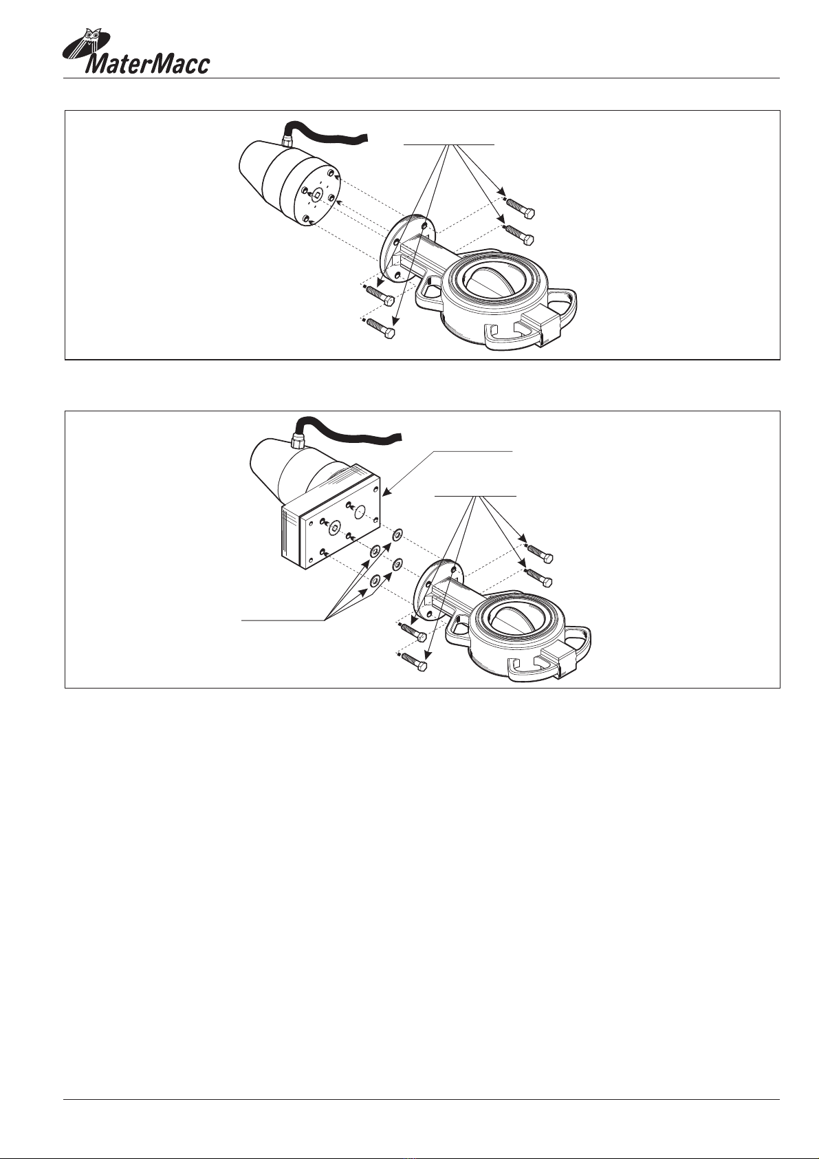
By-pass valves consist of a 100 mm long body with
female gas threading at the ends and a head gasket
for wafer mounting. A butterfly valve with an
elastic rim is mounted inside The motor reduction
gear is fitted on the valve shaft. The motor
reduction gear is controlled by the gearcase for
speed adjustment.
4.1.2 HOW TO MOUNT THE BY-PASS VALVE
Fit the by-pass valve in the by-pass duct of the
turbine in such a position as to prevent the motor
reduction gear from getting upside down to
prevent water seepage . The duct with the by-pass
valve should not be rigid, but at least with a section
of rubber or plastic hose to prevent any damage to
the valve.
Page 03

IRRIGAMATIC ASSEMBLING
4.1.3 MOTOR REDUCTION GEAR
INSTALLATION
Insert the motor reduction gear in the valve shaft in
such a way as to position the shaft plug in the motor
reduction gear seat. Insert the locking pin of the motor
reduction gear in the slot of the valve body, then lock
the unit by straps as shown in the figure below.
Fix the motor reduction gear cable to the irrigator
frame by straps or cable holders as far as the
electronic gearcase.
The rewinding speed adjustment for piston irrigators
is obtained by means of a ball valve (¾”) with a
female to female threading on which the motor
reduction gear is applied.
The ball head valve is preferably installed in the
delivery hose taking water to the piston, but it can
be installed in the water drain as well.
The motor reduction gear cable bears a ring with
number 4 and should be connected to gearcase
connector 4.
For installation follow the instructions given for
by-pass valve installation.
4.2 INSTALLATION OF A BALL VALVE
FOR PISTON IRRIGATORS
Each valve is supplied with a manual
adjustment dial that can be very useful
should the adjustment system be out of
order, in that it permits to keep the valve
approx. in a working position anyway.
!!! NOTE !!!
5 INSTALLATION OF THE
END-OF-WORK VALVE
5.1 SHUNT VALVE
The shunt valve is a 3-way motor-driven valve used
to pilot a hydraulic valve to discharge pressure from
the duct and stop the irrigation cycle.Choose the
position for the shunt valve and fix it with its
support vertical by two screws.
Fix the 3-way valve motor cable to the irrigator
frame by straps or cable holders as far as the
electronic gearcase.
The 3-way valve motor cable bears a ring with
number 5 and should be connected to gearcase
connector 5.
Connect the shunt valve to the hydraulic valve as
shown in the diagram below.
The hydraulic valve is usually fitted on the hose to
the drain.
To connect the shunt valve to the hydraulic valve,
use a plastic hose (6 or 8 mm diameter) and fittings.
The shunt valve is a threaded 1/8” female.
Upon request a 5-way valve can be supplied to
control a double-acting piston.
Page 04

IRRIGAMATIC ASSEMBLING
5.2 SLOW- CLOSING VALVE
The slow-closing valve consists of a motor-driven butterfly valve. It can be mounted on the inlet (closing in
approx. 4 minutes) to close the water delivery to the irrigator or on the drain (opening in approx.1,5 minutes) to
let pressure drop.
- one for valves (diameter up to 3”)
- one for valves (diameter of 4” and over) (with an extra reduction gear).
Fit the valve in the inlet or outlet duct to prevent the motor reduction gear from capsizing and avoiding
water seepage.
Fit the motor reduction gear in the valve square shaft and fix it to the valve body by means of 4 screws (see
figure)
Two types of motor reduction gears are mounted:
5.2.1
5.2.2
HOW TO MOUNT THE BUTTERFLY VALVE
MOTOR REDUCTION GEAR INSTALLATION
5.1.1 DIAGRAM OF THE HYDRAULIC VALVE TO THE DRAIN
Page 05
DRAIN
PIPE UNDER PRESSION
HYDRAULIC VALVE
SHUNT VALVE
CONIC MOTOR
MOTOR PICTURE
DRAIN
DRAIN
SIDE SIGHT
SEES FRONTAL
DRAIN
PIPE UNDER PRESSION
HYDRAULIC VALVE
SHUNT VALVE

IRRIGAMATIC ASSEMBLING
Fix the valve motor cable to the irrigator frame by straps or cable holders as far as the electronic gearcase.
The valve motor cable bears a ring with number 5 and should be connected to gearcase connector 5.
Page 06
N° 4 RONDELLE M8
N° 4 VITI TE M8X25
MOTORIDUTTORE
VALVE 3"
VALVE 4"- 5"
N° 4 VITI TE M8X25

IRRIGAMATIC ASSEMBLING
6 INSTALLATION OF THE
END-OF-REWINDING
SENSOR
7 ELECTRONIC CONSOLE
INSTALLATION
The end-of-rewinding sensor is used to give the
gearcase consent to start the procedures of end-of-
work once the whole hose has been rewound.
Fix the magnet on the transmission rod at a maximum
distance of 5 mm in front of the sensor. The sensor
should be fixed on the frame by means of a bracket to
obtain the above described condition.
Make sure the distances are complied with and the
magnet passes close to the sensor tip without
damaging it.
Fix the end-of-rewinding sensor cable to the irrigator
frame by straps or cable holders as far as the electronic
gearcase.
The eletronic console must be installed on the
irrigator frame in an accessible position, far from heat
sources (for ex. engine) and away from vibrations.
It can be installed in a stainless steel optional
protective case.
Open the eletronic console and bore the holes
necessary to led the cable through on the bottom and
on the cable holder.
Fix the eletronic console bottom in the required
position.
Connect the motor cables and the sensor cables in
their positions (see electric diagrams on pages 10-11)
making sure not to make any mistakes.
Connect the main cable bearing a ring with number 1
to terminal board 1. Of the eletronic console.
The end-of-rewinding sensor cable bears a ring
with number 3 and should be connected to
gearcase connector 3.
CHECK POLARITIES
CONNECT RED CABLE WITH POLE +
CONNECT BLACK CABLE WITH POLE -
Fit the front and close the eletrocic console.
Connect the power supply cable to a 12V
battery.
Fix the various cables by straps and cable holders.
The system is now ready to operate.
The average consumption of an Irrigamatic
appliance is approx. 40-50 mA. This means that a
50 Ah battery should last approx 1000 h under
normal conditions.
Power supply to the battery can be obtained by an
optional photovoltaic panel .(OPTIONAL)
Page 07
CHECK POLARITIES
CONNECT RED CABLE WITH POLE +
CONNECT BLACK CABLE WITH POLE -

IRRIGAMATIC ASSEMBLING
8. OPTIONS
8.1 PRESSURE SWITCH
INSTALLATION
The Irrigamatic machines are preset for direct
connection to the electronic gearcase of a pressure
switch used to inform the system about any leak of
pressure in the duct.
The supplied pressure switch has a male threaded 1/8”
connection. The pressure switch should be installed at
the top of the duct to prevent impurity from
depositing on the bulb.
NO
OK
8.1.1 HOW TO CALIBRATE THE PRESSURE
SWITCH
Upon supply, pressure switch calibration is
random. To modify this value , remove the cover
and act on the screw fitted on the pressure switch.
Tighten the screw to increase pressure, loosen the
screw to reduce it.
The contacts are normally closed and open when
the operating pressure is higher than the preset
pressure.
In PRO35 - PRO45 models (preset appliances) an
outer alarm (beeper, flashing light or other) the
power supply of which is obtained directly from
the battery.
It is controlled by an outer gearcase relay that can
stand a maximum current of 5A. The relay contacts
close after unwinding (if the sensor is installed)
and, for one minute, at the end of the irrigation
cycle, or in case of trouble.
The pressure switch cable bears a ring with
number 7 and should be connected to gearcase
connector 7.
The outer alarm system should be connected to
connector 10.
8.2 OUTER ALARM
Page 08

IRRIGAMATIC ASSEMBLING
9. SCHEME
Page 09
Alim12Vcc +
-
+-
+ 12V
- +
SEN
1 2 3 4 5 6 7 8 9 10
End rewinding
Motor
Reg
Motor
Flow
Flowmeter
Pressuse
End unwinding
IRRIGAMATIC AND CONNECTION DIAGRAMPRO35 PRO45
blue -
black
brown +
1 - POWER SUPPLY:12 Vcc
2 - INDUCTIVE PROXIMITY SPEED SENSOR (PINION)
3 - END-OF-REWINDING SENSOR
4 - SPEED ADJUSTMENT MOTOR: 12Vcc
5 - END-OF-WORK VALVE MOTOR: 12Vcc
6 - END-OF-UNWINDING SENSOR (OPTIONAL)
7 - PRESSURE SWITCH (OPTIONAL)
8 - PULSE FLOWMETER (5 - 180 pulses/ litre)
9 - WIND/RAIN SENSOR
10 - CONTACT FOR FLASHING LIGHT/RADIO SIGNAL, etc. (maximum charge 5A)
Wind/rain Sensor

IRRIGAMATIC ASSEMBLING
Page 10
10 MODALITY OF USE
10.1 SWITCHING THE ELETRONIC
CONSOLE ON
Connect the power supply cables of the eletronic
console at a voltage of 12V d.c.
When power is supplied to the eletronic console the
LCD displays the logo and version of the firmware.
Ver. 0.x(x)
A message follows informing about the execution of
the machine initialization. the flow valve is closed if
located at the inlet.
CHIUSURA FLUX
The BYP valve opens to make sure speed is set to
zero.
BYP OPENING
followed by a message of confirmation that the device
initialization has been carried out.
INIT
OVER
The gearcase then goes to standby waiting for new
commands by the user who can access the menus
listed below:
IRR. 2K7 PRO
01/01/08 12:00:00
To scroll the menus just rotate the knob right or left.
In order to select a menu just press the knob on the
menu item that is being high lighted.
The highlighting is obtained with an inverted
contrast.
10.2 ACCESS TO MENUS
General procedure
The eletronic console then goes to standby waiting
for new commands by the user who can access the
menus listed below:
To access the menu specified in the paragraph
proceed as follows:
1. Highlight the relevant menu
scroll the menus by turning the knob right or left.
2. Press the knob
3.If the menu is password-protected the
“PASSWORD” label will be displayed and the
characters composing the relevant password
shall be entered.
4. To enter the password:
A) Press the knob the first character is displayed as
“A*” meaning the character can now be edited.
B) Modify the character by turning the knob right or
left.
C) Confirm the character you have selected by
pressing the knob.
D) Highlight the next position by turning the knob
right or left.
E) Repeat A) to D) to the last character then high
light and press the knob; if the password
is correct, the electronic console will display the
first of the menu parameters otherwise it will be
locked on the password menu. To quit the menu
high light and the electronic console will
return to the main menu.
NEXT
BACK
OPERATION
CALIBRATION
CONFIGURATION
CALENDAR
COUNTER

IRRIGAMATIC ASSEMBLING
Page 11
NEXT
NEXT
11 CONFIGURATION
The IRRIGAMATIC gearcase requires programming
the parameters needed to configure the device in view
of the irrigator equipment and features.
Possible mistakes in programming these parameters
would jeopardize the operation of the irrigator badly.
To prevent non-authorized people from changing
these parameters by mistake the gearcase is password
protected.
This access password is personalized for every
manufacturer. It is entered by MATERMACC and
communicated only to the interested parties.
Highlight by turning the knob on
CONFIGURATION and press the knob.
The system displays::
. Highlight by turning the knob on
the 1st character and press the knob.
11.1 LOADING PROCEDURE
FOR CONFIGURATION PARAMETERS
1.
2
PASSWORD
--- --- --- ---
3 $ 6 6 : 2 5 '
3 $ 6 6 : 2 5 '
Will be displayed. Modify the first code number by
turning the knob and confirm by pressing the knob.
The display will read for example:
Move the focus on to the second position and repeat
2 to 3 until the code has been completed. The
following will be displayed, for ex.:
*
PASSWORD
0 1 2 3
#
#
5.
6.
7.
8.
9.
Highlight by turning the knob on it
and press the knob. If the password is correct the
following will be displayed:
To change the parameter value rotate the knob
until the value is highlighted and press the knob.
The following will be displayed, for ex.:
Modify the value by turning the knob right or left
and confirm by pressing the knob again. The
following will be displayed for ex.:
Keep scrolling the parameters by highlighting
If necessary repeat 6 and 7 to modify other
parameters.
To quit the configuration menu reach the
pseudo-parameter “ highlight it and
press the knob:
#
IMPUT
<- ESC ->”,
IMPUT*
EXIT
<- ESC ->

IRRIGAMATIC ASSEMBLING
Page 12
NEXT
NEXT
12 CALIBRATION
Accessible only if a machine with roll on pinion has
been selected in configuration. The calibration menu
is password protected. Accessible only through the
passwords reserved to the irrigator's manufacturer.
Highlight by turning the
knob and press it to display:
12.1 LOADING PROCEDURE
FOR CONFIGURATION
PARAMETERS
1. CONFIGURATION
_ _ _ _ _ _ _ _ _ _ _ _
PASSWORD
Highlight the 1st character position by turning the
knob and press it to display:
Modify the first code number by turning the knob
and confirm by pressing it. The following will be
displayed, for ex.:
Highlight the second position and repeat 2 and 3
until the code has been completed. The following
will be displayed, for ex.:
Highlight by turning the knob on it
and press the knob. If the password is correct
the following will be displayed:
PASSWORD
PASSWORD
PASSWORD
_ _ _ _ _ _ _ _ _
_ _ _ _ _ _ _ _ _
4.
5.
0 1 2 3
0*
0
CAL. TYPE
MANUAL x
AUTOMATIC
6. To select the calibration type you intend to carry
out, highlight the required item and press the knob.
Then highlight and press the knob again. If
selection was chosen, the following will
be displayed:
MANUAL

IRRIGAMATIC ASSEMBLING
To continue highlight by rotating the knob and
then press it.
The electronic console goes to layer 2; the
following is displayed:
Repeat the operations 7 through 9 to the last
required layer. The gearcase will quit the calibration
by highlighting
by pressing the knob on a layer with zero meters and
pulses.
during calibration pulse count can be
suspended (for example to face an unexpected
situation) by highlighting “IMP. Xx” and pressing the
knob. The following will be displayed:
To resume calibration highlight ”PAUSE” and press
the knob.
P P P L
,0 3
&$ / ,%5 $ 7,2 1
/ $ <( 5
P P P L
CALIBRATION
LAYER
NOTE.
3 $ 8 6 (
NEXT
NEXT
Page 13

IRRIGAMATIC ASSEMBLING
13 PARAMETERS RESERVED TO THE MANUFACTURER
(PASSWORD:“CSTR”)
Below please find the description of the configuration parameters for IRRIGAMATIC.
Page 14
#1 Flow valve position. This parameter can also be
displayed by the final user if he/she has a
password for it
0 = inlet
1 = discharge
0
#2 Time out on flow valve openong if located at the inlet. 300 S
#3 Time out on flow valve closing if located at the outlet. 300 S
#4 Time out on flow valve opening if located at the
outlet.
300 S
#5 Time out on flow valve closing if located at the
outlet.
300 S
#6 Pulsed opening time for flow valve 120 S
#7 Constant closing time for flow valve 120 S
#8 Mult. factor to re-initialize the speed buffer with the
minimum speed value in order to adjust it with long
pulses.
5
#9 Mult. factor to determine whether the trolley has been
lost.
15
#10 Timeout on bypass valve opening. 60 S
#11 Timeout on bypass valve closing. 60 S
#12 Standby time for zero pressure. 10 Min.
#13 Pressure switch position. “0” = absent;
1 = downstream
flow valve NA
2 downstream
flow valve NC
3 = upstream flow
valve NA
4 = upstream flow
valve NC
=
1
#14 Position of the speed sensor. 0 = on roll
1 = on pinion
0
#15 Number of pulses of the speed sensor that are
ignored.
0
#16 Sensor of end of unwinding DEVHQW
SUHVHQW
1
Parameter Description

IRRIGAMATIC ASSEMBLING
Page 15
#17 Sensor of end of winding up. Flow valve position.
This parameter can also be displayed by the final user if
he has a password for it:
DEVHQW
SUHVHQW
1
#18 Sensor rain wind
SUHVHQW
DEVHQW 0
#19 &ULWHULRQRI UHJXODWLRQ
P P
speed of
return
water
0
#20 Average flow rate value(flowmeter data). This
parameter can also be displayed by the final user
if he has a password for it:
1000 OP LQ
#21 Average flow rate value(flowmeter data). This
parameter can also be displayed by the final user
if he has a password for it:
1000 OP LQ
#22 Max flow rate value at the signal of 20 mA
(flowmeter data). This parameter can also be
displayed by the final user if he has a password for
it.
2700 OP LQ
#23 Percentage of the measured flow rate defining the
symmetrical hysteresis during irrigation per mm of
water. This parameter can also be displayed by the
final user if he/she has a password for it.
5
#24 Conversion factor for the speed sensor if the sensor
is the feeling roller type mm/pulse.
100 P P L
P SXOV
H
#25 Length of the most external layer 10. 50 P
#26 Conversion factor for the speed sensor for layer 10
if the sensor is the pinion mounted type mm/pulse.
100 P P L
P SXOV
H
#27 Length of layer 9. 50 P
#28 Conversion factor for the speed sensor for layer 9 if
the sensor is the pinion mounted type mm/pulse.
100 P P L
P SXOV
H
#29 Length of layer 8. 50 P
#30 Conversion factor for the speed sensor for layer 8 if
the sensor is the pinion mounted type mm/pulse.
100 P P L
P SXOV
H
#31 Length of layer 7. 50 P P
LP SXOV
#32 Conversion factor for the speed sensor for layer 7 if
the sensor is the pinion mounted type mm/pulse.
100 P P L
P SXOV
H
#33 Length of layer 6. 50 P
Parameter Description

IRRIGAMATIC ASSEMBLING
Page 16
#34 Conversion factor for the speed sensor for layer 6 if
the sensor is the pinion mounted type mm/pulse.
100 P P
LP SXOV
R
#35 Length of layer 5. 50 P P
LP SXOV
R
#36 Conversion factor for the speed sensor for layer 5 if
the sensor is the pinion mounted type mm/pulse.
100 P P
LP SXOV
R
#37 Length of layer 4. 50 P
#38 Conversion factor for the speed sensor for layer 4 if
the sensor is the pinion mounted type mm/pulse.
100 P P
LP SXOV
R
#39 Length of layer 3. 50 P
#40 Conversion factor for the speed sensor for layer 3 if
the sensor is the pinion mounted type mm/pulse.
100 P P
LP SXOV
R
#41 Length of layer 2. 50 P
#42 Conversion factor for the speed sensor for layer 2 if
the sensor is the pinion mounted type mm/pulse.
100 P P
LP SXOV
R
#43 Length of layer 1. 50 P
#44 Conversion factor for the speed sensor for layer 1 if
the sensor is the pinion mounted type mm/pulse.
100 P P
LP SXOV
R
#45 Total hour counter. 07LP HV
#46 Partial hour counter. 07LP HV
#47 Measure units in use
This parameter can also be displayed by the final
user if he has a password for it:
0 = meters
1 = feet
0
#48 Language of the texts 0 = Italian
1 = English
2 = German
3 = French
0
#49 Diameter of the reel used for mathematical
calibration
This parameter can also be displayed by the final
user if he has a password for it:
1400 P P
#50 Width of the reel used for mathematical calibration
This parameter can also be displayed by the final
user if he has a password for it:
2000 P P
Parameter Description
Other manuals for IRRIGAMATIC PRO35
1
This manual suits for next models
1
Table of contents
Other Matermacc Desktop manuals