matev SBL-M 12-40C Installation instructions

matev GmbH
Nürnberger Str. 50
90579 Langenzenn, Germany
T +49 9101 9087 -0
F +49 9101 9087 -20
www.matev.eu
Version 12/2017
Original Operating Manual
Snow Blower
SBL - M 12-40 QH –JD Quick Hitch
SBL - M 12 –40C
SBL - M 14 –40C
Carefully read this manual all the way through before using the machine.

Page 2
Table of contents
1About this operating manual....................................................................................3
2Safety.........................................................................................................................4
2.1 Intended use...............................................................................................................4
2.2 Qualifications of personnel..........................................................................................4
2.3 General safetynotices .................................................................................................5
2.4 Special safety notices .................................................................................................6
2.5 Basic rules..................................................................................................................7
3Task and use.............................................................................................................7
4Delivery and transport..............................................................................................7
5Installation.................................................................................................................8
5.1 Mounting the snow blower on the tractor.....................................................................8
5.1.1 Mounting snow blower SBL - M 12-40 QH an JD X700...............................................8
5.1.2 Mount snow blower SBL - M 12-40 C and SBL - M 12-40 C on tractor........................9
5.2 Installation of the universal joint shaft........................................................................10
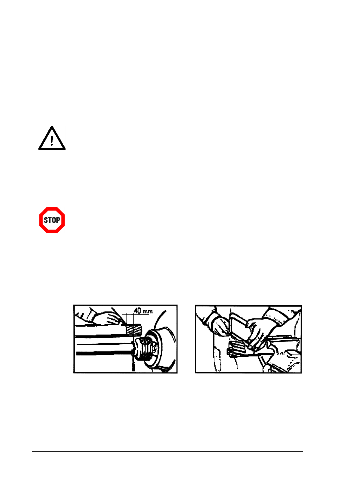
5.2.1 Adaptation of the universal joint shaft........................................................................10
5.2.2 Mounting the universal joint shaft..............................................................................11
6Operation.................................................................................................................12
6.1 Working with the snow blower...................................................................................12
6.2 Adjusting the work height of the machine..................................................................13
7Maintenance............................................................................................................13
7.1 General information...................................................................................................13
7.2 Maintenance .............................................................................................................14
7.2.1 Front auger and deflector group................................................................................14
7.2.2 Safety screw.............................................................................................................15
7.2.3 Throw-out tower........................................................................................................15
7.2.4 Gearbox....................................................................................................................16
7.2.5 Lubricating the universal joint shaft...........................................................................17
7.3 Faults........................................................................................................................17
7.4 Repair.......................................................................................................................18
8Disposal...................................................................................................................18
9Guarantee................................................................................................................18
10 Technical data, implements and optional equipment...........................................19
11 List of illustrations..................................................................................................20
12 EC Declaration of Conformity ................................................................................21

About this operating manual
Page 3
1 About this operating manual
Dear customer!
Thank you for purchasing this snow blower, we appreciate your trust.
Prior to using this implement for the first time, read this operating manual carefully and
conscientiously all the way through.
Keep this operating manual where it is easily accessible. This will enable you to refer to
important information and handling instructions as needed.
Listings with bullet points are marked as follows:
Text
Text
Text
Handling instructions are marked in the sequence in which they should be executed, as
follows:
1. Text
2. Text
3. Text
The snow blower is subject to change in the interest of technical progress.
All information, illustrations, and technical specifications represent the
latest status at the time this manual was published. The manufacturer
reserves the right to make changes at any time in the interest of technical
progress.

Safety
Page 4
2 Safety
Note
Must be read!!!
Guidelines and instructions with which you must comply, are summarized in this section.
Personnel who install, operate and maintain the snow blower, must have read and
understood this operating manual.
2.1 Intended use
The implement is used exclusively in winter service for clearing snow on roads,
lanes, walking paths, plazas, and industrial areas.
Any use extending beyond the intended use cited above is considered non-
intended use. The manufacturer bears no liability whatsoever for resulting damage;
the risk associated with non-intended use is borne solely by the operator.
Intended use also includes compliance with the operating, service, and
maintenance conditions prescribed by the manufacturer.
The implement should only be used, maintained, and repaired by persons who are
familiar with these tasks and who have been instructed in the hazards.
Moreover, intended use includes exclusive use of original spare parts and
supplemental equipment, or use of such parts and equipment that meet the
technical requirements specified by the manufacturer.
Unauthorized modifications to the machine result in exclusion of liability on the part
of the manufacturer. For the resulting damage, in the case of non-intended use:
Health hazards for the operator or for third parties
Damage to the tractor and the implements
Environmental damage
immediate invalidation of the warranty
To avoid accidents and to reduce the risk of accidents, the relevant accident
prevention regulations and the other generally acknowledged occupational health
and safety and road traffic regulations apply without limitation.
2.2 Qualifications of personnel
Only persons who meet the following qualifications should mount, operate, and maintain
the implement:
They must be at least 18 years old.
They must have read and understood this operating manual.

Safety
Page 5
2.3 General safetynotices
In this section general safety notices are explained that are used in the subsequent
sections.
Comply with these safety notices to ensure safe operation and to save work time and
costs.
In addition to the instructions in this operating manual, also comply with the
generally valid safety and accident prevention regulations! Young persons under
the age of 16 are not allowed to operate the implement!
Comply with the respective regulations for use on public traffic routes!
Prior to commencing work, become familiar with all features and activation
elements, and their function. Ensure that all protective devices are properly
attached.
The user is responsible to third persons in the work area!
Do not enter the danger zone of the machine!
Check the immediate vicinity of the implement before start-up. Ensure sufficient
visibility!
Fluids (hydraulic oil) escaping under high pressure can penetrate the skin and
cause severe injuries. Seek medical attention immediately –danger of infection!
Always execute repair, maintenance, and cleaning tasks, as well as rectification of
malfunctions with the drive switched off and the engine at a standstill. Remove the
ignition key! After execution of these tasks re-attach all protective devices!
For maintenance tasks with the implement lifted, always ensure that the lifted
implement is secured with suitable support elements!
These safety notices are used in the subsequent sections.
Danger!
Severe injury to the operator or third parties occurs.
Comply with the safety notice.
Attention!
Minor injury to the operator or third parties can occur. The walk-behind
tractor, the sweeper or the environment can be damaged. Comply with the
safety notice.
Note!
Important, helpful tips or information for the operator.
Read this note. It facilitates your work.
Attention!
Injuries can occur.
Wear protective work clothing.

Safety
Page 6
2.4 Special safety notices
The safety instructions specified in this section are also affixed as stickers on the
implements.
Attention!
Ensure that the engine PTO shaft is at a standstill.
Only use cloths, water soap for cleaning. Do not use any solvents, diesel
fuel or gasoline. Replace damaged signs. If the sign is on a component that
must be replaced, you must ensure that a new sign is affixed on the spare
part.
1 - Carefully read the operating manual before commissioning the machine
- Danger entanglement
Danger of hand or arm injuries
- Ensure that the complete machine is at standstill before you approach it
- Danger due to ejected objects
Always maintain a safety distance while the snow blower is in operation
- Danger of hand and arm injuries
Always maintain a safety distance while the snow blower is in operation
2-Pay attention to the direction of rotation as well as
the specified rotational speed
3-Identification of the lubrication point
4 - Hard point for lifting the equipment.
Use suitable lifting gear and
prescribed accessories.
5
-Use of personal
protective equipment (PPE) is mandatory

Delivery and transport
Page 7
2.5 Basic rules
Each time before starting up, check the machine for operational reliability!!!
Cleaning tasks, e.g. with a high-pressure cleaner, should be executed in such
a manner that the water jet is not held directly on bearing parts and turned
parts (shaft seals, lubricating nipples, etc.) Otherwise, check the moving
parts for ease of movement, regrease if necessary!
Failure to comply with these instructions invalidates the guarantee claim.
3 Task and use
In conjunction with a tractor the snow blower is used to clear large quantities of snow off
of roads, lanes, walking paths, plazas and industrial areas.
The snow blower clears off snow, with the exception or wet snow or frozen snow. The
work speed depends on the depth of the snow.
The implement is mounted on the tractor as a front attachment is driven by the tractor via
a universal joint shaft. The throw direction of the machine can be rotated hydraulically.
The baffle plate for setting the throw distance can be adjusted either electrically or
hydraulically.
All work functions must be controlled from the driver seat.
4 Delivery and transport
The snow blower is delivered lashed on a
pallet.
Lifting the snow blower off of the pallet
1. Remove the protective packaging and the
transport safeguard.
2. Lift the snow blower off of the pallet with a
suitable device (crane or forklift) and set it
down.
Use the intended points for lifting, so that
the implement remains properly balanced
Only use belts and ropes with a safety
lock!
To not turn the lifted implement.
Fig. 1: Attachment point
Long-distance transport
If you want to transport the snow blower over longer distances (e.g. shipping via freight
forwarder), you must lash the machine onto a pallet, as it was when it was originally
delivered.

Installation
Page 8
5 Installation
Danger!
Switch off the tractor and remove the ignition key before mounting or
dismounting the implements.
Note!
Enter the vehicle chassis number of the snow blower in section 7.4 of this
operating manual.
The rear axle of the vehicle is offloaded depending on the weight of the equipment. To
avoid loss of adhesion, the weight on the off-loaded axle must be at least 25% of the
empty weight of the vehicle. If required, or if possible put on chains. Check the lift
capacity and the stability, and if required, weight with ballast, to prevent the vehicle from
tipping.
In the movement phase the load on the equipment must be at maximum of 400 mm
above the ground, so that the vehicle does not lose stability.
5.1 Mounting the snow blower on the tractor
Attention!
The connection between attachment on the snow blower and coupling
support on the tractor must be safeguarded against uncoupling.
5.1.1 Mounting snow blower SBL - M 12-40 QH an JD X700
With the JD attachment –as shown in the photos, approach the snow blower
pick up the bolts of the snow blower with the JD attachment
With bolts left and right on the JD receptacle lock the snow blower
Fit on universal joint shaft ad hydraulic connections
Fig. 2: Attach SBL - M 12-40 QU Fig. 3: Attach SBL - M 12-40 QU
bolts
JD - attachment

Installation
Page 9
5.1.2 Mount snow blower SBL - M 12-40 C and SBL - M 12-40 C on tractor
Depending on tractor size and type and size of the coupling support, the attachment
triangle on the snow blower is fastened with screws. The height of attachment must be
selected depending on the tractor size. The attachment can also be shifted in length.
Fig. 4: Attachment of the snow blower
The connection between coupling support and attachment must be secured against
uncoupling of the connection, depending on the design of the attachment.
Possible securing options are:
Peg with bolts and secure with cotter pin
Fasten with screw
Secure with catch
Via the top link the snow blower is aligned horizontally to the ground.
Fig. 5: Adjusting the snow blower

Installation
Page 10
5.2 Installation of the universal joint shaft
The transmission of force between tractor and snow blower occurs mechanically via a
universal joint shaft.
Depending on tractor type the supplied universal joint shaft may be too long. Execute the
steps described below to shorten the universal joint shaft. Only use the universal joint
shaft provided by the manufacturer.
Attention!
Damage can occur to the attached implement or on the tractor.
Only use the provided universal joint shaft.
Note!
In addition, when mounting the joint shaft, comply with the instructions in
the original manual provided by the manufacturer of the universal joint
shaft.
The safety and maintenance instructions that are contained in the operating
manual provided with the universal joint shaft, must be strictly complied
with!
5.2.1 Adaptation of the universal joint shaft
1. Pull the two halves of the universal joint shaft apart.
2. Mount the one end of the universal joint shaft on the tractor.
3. Mount the other end of the universal joint shaft on the implement.
4. In the shortest work position, mark the piece that will be sawn off on one half of the
universal joint shaft.
Fig. 6: Mark the interface Fig. 7: Saw off the universal joint shaft
5. Cut off the universal joint shaft guard to the marking.
6. Saw off the profile tube. Attention: The profile tube must be 10 mm longer than the
guard.

Installation
Page 11
Fig. 8: Saw off the profile tube Fig.9: Deburr the sawn edges
7. Repeat steps described steps on the other half of the universal joint shaft.
8. Deburr the sawn edges.
9. Grease the profile tube.
Fig. 10: Grease the profile tube.
10. Slide the profile tubes together.
5.2.2 Mounting the universal joint shaft
1. Press the locking disk that is on the outer side and keep it depressed.
2. Slide the splined shaft onto the splined shaft of the PTO shaft.
3. Release the lock disk.
4. Slightly move the universal joint shaft back and forth until the locking disk audibly
locks in place.
Fig. 11: Allow the locking disk to lock in place
5. Connect the counter-piece of the shaft with the implement and secure this with the
screw included in the scope of delivery.
6. Hook the universal joint shaft safety chains to a stationary part on the tractor and on
the implement.

Operation
Page 12
6 Operation
6.1 Working with the snow blower
Attention!
The vehicle behavior, steering and brake capacity are influenced through
the attached equipment
Attention!
The snow blower can be damaged. Before each use, check to ensure proper
adjustment of the support skids.
Only operate the snow blower from the driver’s seat of the tractor.
Attention!
Third persons can be severely injured and objects can be damaged. Ensure
for yourself that no objects are concealed under the snow. When operating
the snow blower no one should be in a radius of 50 m around the machine,
as a precaution against being caught by the rotor, in addition rocks or
similar objects can accelerated to the front through the rotor. Consequently
always maintain an adequate distance to persons who could be injured or
objects that could be damaged.
The manufacture accepts no liability in such cases of injury or damage.
1. Lower the snow blower.
2. Switch the hydraulics to the float setting.
3. Bring the throw-out tower into the desired position
4. Switch on the machine on a surface that is free of snow, at 80% engine speed and
the maximum speed can be reached incrementally.
5. Move forward at an appropriate speed. The snow can be optimally cleared at a
consistency of 80-140 Kg/m3 (new snow) or also in compact but slightly frozen
(crystalline) condition.
6. When driving, always check the direction of the throw-out tower, so that snow does
not hit people or objects.
Attention!
The pivoting must always occur with the utmost safety and the tower must
not be directed at persons, dangerous locations or places.
The tower is pivoted hydraulically, mechanical standstill is not intended, and
consequently you must ensure that the hydraulic lines do not wrap around
the tower.
7. End of work: Bring the vehicle to a standstill and only switch off the tractor PTO shaft
when the tower is completely empty.

Maintenance
Page 13
6.2 Adjusting the work height of the machine
Note!
Adjust the support skids of the machine in such a manner that in working
position the snow blower glides just barely above the ground. Watch out for
uneven terrain, projecting edges and objects, such as manhole covers and
shaft covers, to prevent machine damage.
1. Flip the anti-rotation lock of the height adjustment element upward
2. Turning the handle adjusts the height of the skid
3. Press the anti-rotation lock downward
4. Adjust the second skid to the same height!
On non-paved roads the turbine must be kept several centimeters above the ground, to
prevent rocks or other material from accumulating through the front auger.
7 Maintenance
7.1 General information
Attention!
Personal injury or damage to the tractor and the implements can occur.
Before each use of the implements check all safety-relevant parts and the
hydraulic connections.
Danger!
Only perform service and maintenance tasks when the tractor is
switched off and the snow blower is on the ground.
Attention!
Remove the ignition key before performing maintenance tasks on the
implement.
Attention!
Danger of crushing due to moving parts.
Never reach into the crushing hazard zone if parts are moving or can move.
If there is pressure loss there is danger of crushing and shear injuries in the
lift-out mechanism.

Maintenance
Page 14
Attention!
Properly reattach all protective devices that have been dismounted after
executing the maintenance tasks.
Note!
After the first 20 hours of operation check all screw and bolt connections.
Subject the implement to regular maintenance.
Use multi-purpose grease to lubricate the moving parts.
7.2 Maintenance
At regular intervals, and always at the beginning and end of the season, the moving parts
of the implement must be greased or oiled.
7.2.1 Front auger and deflector group
After ending work any snow remaining in the turbine must be removed with the aid of the
provided wooden rod, and you must check whether the screws for the blade (A) and the
holder of the deflector group (B) are firmly seated (B).
Fig. 12: Front auger and deflector group
Check whether the augurs and the throw blades turn freely, otherwise you must check
whether the bearings and the side holders (C) are still intact.
If during use you determine that you have hit a rock or other object, you must check
whether the augurs and the throw blades have become deformed, if they have the
defective parts must be replaced to prevent imbalance and machine vibration.
If unusual vibration occurs on the machine, the cause must be identified and rectified
immediately; do not, under any circumstances, continue working

Maintenance
Page 15
7.2.2 Safety screw
Both augurs have a safety screw (D). To prevent transport of heavy material, through
which the equipment can be damaged, the safety screw breaks at a specific load. We
recommend always keeping several replacement screws of the following dimensions with
you when operating the implement.
Fig.13: Auger
7.2.3 Throw-out tower
At the beginning and end of each work cycle, the bearing shell must be greased with
consistency class 2 mineral grease, applied with a grease gun.
With the tower tilted back, grease the continuous flight screw (D).
Fig. 14: Throw-out tower
If the tower opening is clogged, the following must occur:
1. Turn the tower to the machine side.
2. Switch off the vehicle engine.
3. Unscrew the screws F of the protective housing (4x), lift the protective housing and
lift it off to the outside.
4. Use the provided wooden rod to remove snow remaining in the tower.
Remount the protective housing in the same position tighten the screws F.
D for
SBL-M12–40C & SBL-M12-40 QH
2x DIN931 M8x60-10.9
+
2x DIN982 M8 (35 Nm)
SBL - M 14 –40C
2x DIN931 M10x70-10.9
+
2x DIN982 M10 (69 Nm)

Maintenance
Page 16
7.2.4 Gearbox
Fig. 15: Gearbox
Every 400 work hours the oil must be changed at operating temperature. To do this,
remove the two plugs located below and on the filler neck B top up with oil type
VANGUARD HCZ 80W90 –API GL3 up to position (C).
(Changing the oil for the first time is recommended after 80-100 hours).
Fig. 16: Ground clearance of the gearbox

Maintenance
Page 17
7.2.5 Lubricating the universal joint shaft
The universal joint shaft must be greased.
Fig. 17: Universal joint shaft
7.3 Faults
Fault:
Possible cause / rectification:
Snow is no longer thrown out smoothly
Snow adhering on the blades or the rotor:
Switch off the machine and use the provided
wooden rod to remove the snow
Tractor does not work effectively with the
snow blower
Check all moving parts for ease of movement –
tractor power is insufficient for the machine
The tower does not turn
Rotary bearing is iced up, mechanical blocking
of the rotation motor / remove icing through heat
or remove it mechanically
Sheet metal throw-out element cannot be
adjusted
Sheet metal throw out element is iced up –
remove icing through heat or remove it
mechanically,
Check adjustment cylinder for icing or breakage.

Guarantee
Page 18
7.4 Repair
If there are faults, problems, or other indications of malfunction, contact your sales
consultant or contact the manufacturer directly:
matev GmbH
Nürnberger Str. 50
90579 Langenzenn, Germany
Tel.: (switchboard) +49 9101/90 87-0
Enter the article number and the chassis number here.
This information is on the type plate of the implement.
Article number:........................................................................
Chassis number:.....................................................................
8 Disposal
The implements must be disposed of in accordance with the applicable regulations of the
municipality or the country.
Take the parts to the collection points for residual waste, special waste, or recycle them
depending on material.
matev GmbH does not provide any disposal services.
9 Guarantee
The General Terms & Conditions of matev GmbH provide information on the guarantee
conditions.
matev GmbH
Nürnberger Str. 50
90579 Langenzenn, Germany

Technical data, implements and optional equipment
Page 19
10 Technical data, implements and optional equipment
SBL - M 12 –40C (QH) SBL - M 14 –40C
Working width 1200 mm 1400 mm
Weight, approximate 156 kg (165 kg) 240 kg
Min./max. power 20/40 HP 28/55 HP
Working width 650 mm 700 mm
Auger diameter 400 mm 400 mm
Throw blade diameter 390 mm 395 mm
Input speed 2000 rpm 2000 rpm
Oil quantity required for tower regulation (at least 6 liters/min. - max. 25 liters
Oil pressure required for tower regulation 40/60 bar.
Note
The weights cited above are indicative only and are subject to variation, also in function of
the desired applications, as well as special changes.
Fig. 18: Diagram SBL - M 12 –40QH
Fig. 19: Diagram SBL - M 12 –40C Fig 20: Diagram SBL - M 14 –40C

List of illustrations
Page 20
11 List of illustrations
Fig. 1: Attachment point.................................................................................................................................7
Fig. 2: Attach SBL - M 12-40 QU Fig. 3: Attach SBL - M 12-40 QU..........................................................8
Fig. 4: Attachment of the snow blower ..........................................................................................................9
Fig. 5: Adjusting the snow blower..................................................................................................................9
Fig. 6: Mark the interface Fig. 7: Saw off the universal joint shaft......................................................... 10
Fig. 8: Saw off the profile tube Fig.9: Deburr the sawn edges ............................................................. 11
Fig. 10: Grease the profile tube.................................................................................................................. 11
Fig. 11: Allow the locking disk to lock in place ........................................................................................... 11
Fig. 12: Front auger and deflector group.................................................................................................... 14
Fig.13: Auger .............................................................................................................................................. 15
Fig. 14: Throw-out tower............................................................................................................................. 15
Fig. 15: Gearbox......................................................................................................................................... 16
Fig. 16: Ground clearance of the gearbox.................................................................................................. 16
Fig. 17: Universal joint shaft ....................................................................................................................... 17
Fig. 18: Diagram SBL - M 12 –40QH......................................................................................................... 19
Fig. 19: Diagram SBL - M 12 –40C Fig 20: Diagram SBL - M 14 –40C............................................... 19
This manual suits for next models
2
Table of contents
Other matev Snow Blower manuals
Popular Snow Blower manuals by other brands

Craftsman
Craftsman 247.88852 owner's manual

Poulan Pro
Poulan Pro 436134 owner's manual

Briggs & Stratton
Briggs & Stratton Classic 100000 Series Operator's manual

Snapper
Snapper 8526, 9528, 10530, 11532 Operator's manual

Cub Cadet
Cub Cadet 221 HP Illustrated parts manual

Ariens
Ariens Sno-Thro 926321 Owner's/operator's manual