1. Before Repair
1. Turn off the power supply. Using a10 , 10 Wresistor, connect
both ends of power supplycapacitors (C601, C602) inorder to
discharge the voltage.
2. Before turning the power supplyon, after completion of repair,
slowlyapplythe primaryvoltage byusing apower supplyvoltage
controller to make sure that the consumed current at 50 HzinNO
SIGNALmode shouldbe shownbelow with respectto supply
voltage 240 V.
Powersupply
voltage AC 240 V
Consumedcurrent
50 Hz 50 - 180
mA
2. Protection Circuitry
The protection circuitrymayhave operatedif eitherof the following conditions is noticed:
-Nosound isheard when the power issupplied.
-Sound stops during aperformance.
The functions of this circuitryis toprevent circuitrydamage if, forexample, the positive and
negative speakerconnection wires are shorted, orif speakersystems withanimpedance less
thanthe indicatedratedimpedance of this unit are used.
If this occurs, followthe procedure outlinedbellow:
1. Press the Standby/on button, switch to standbymode.
2. Determine the cause of the problem and correct it.
3. Press the Standby/on button once again, supplythe power.
Note:
When the protection circuitryfunctions, the unitwill not operate
unless the Standby/on button isfirst switched Standbyand then
ONagain.
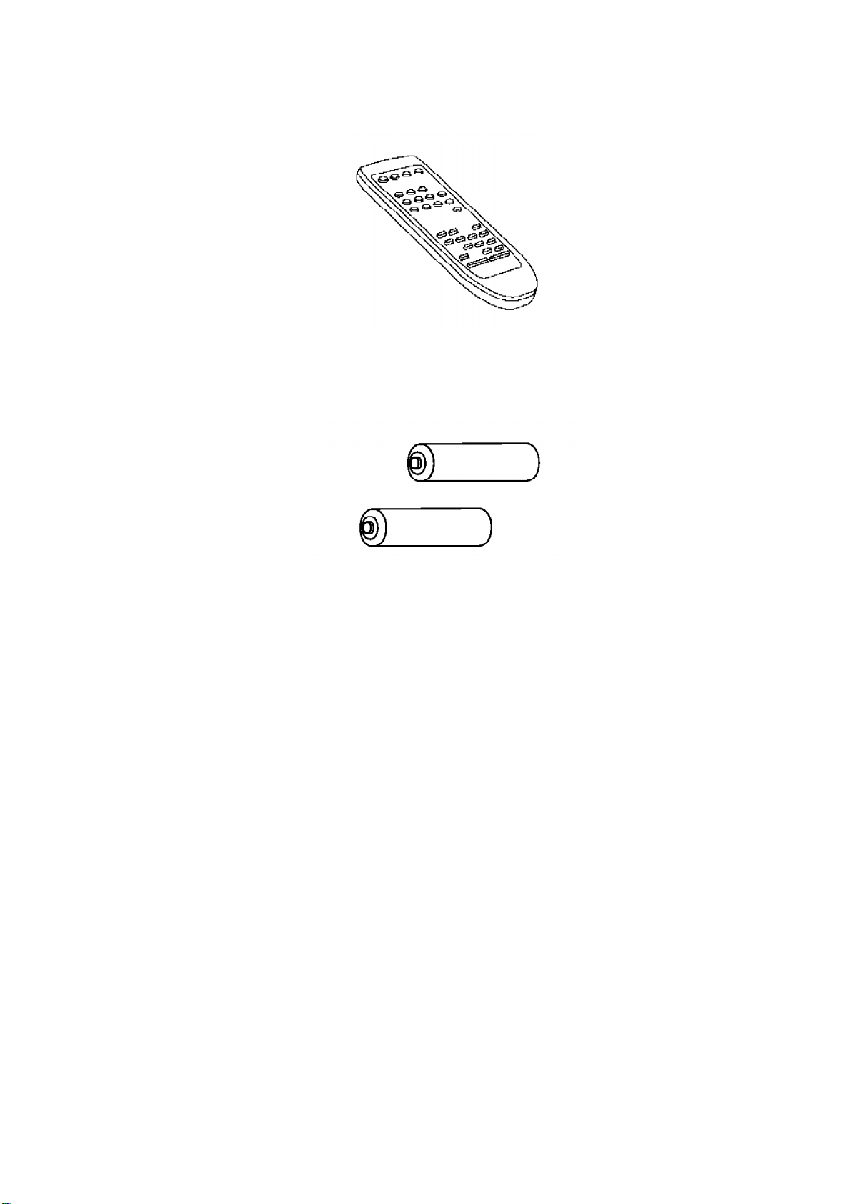
3. Accessories
2