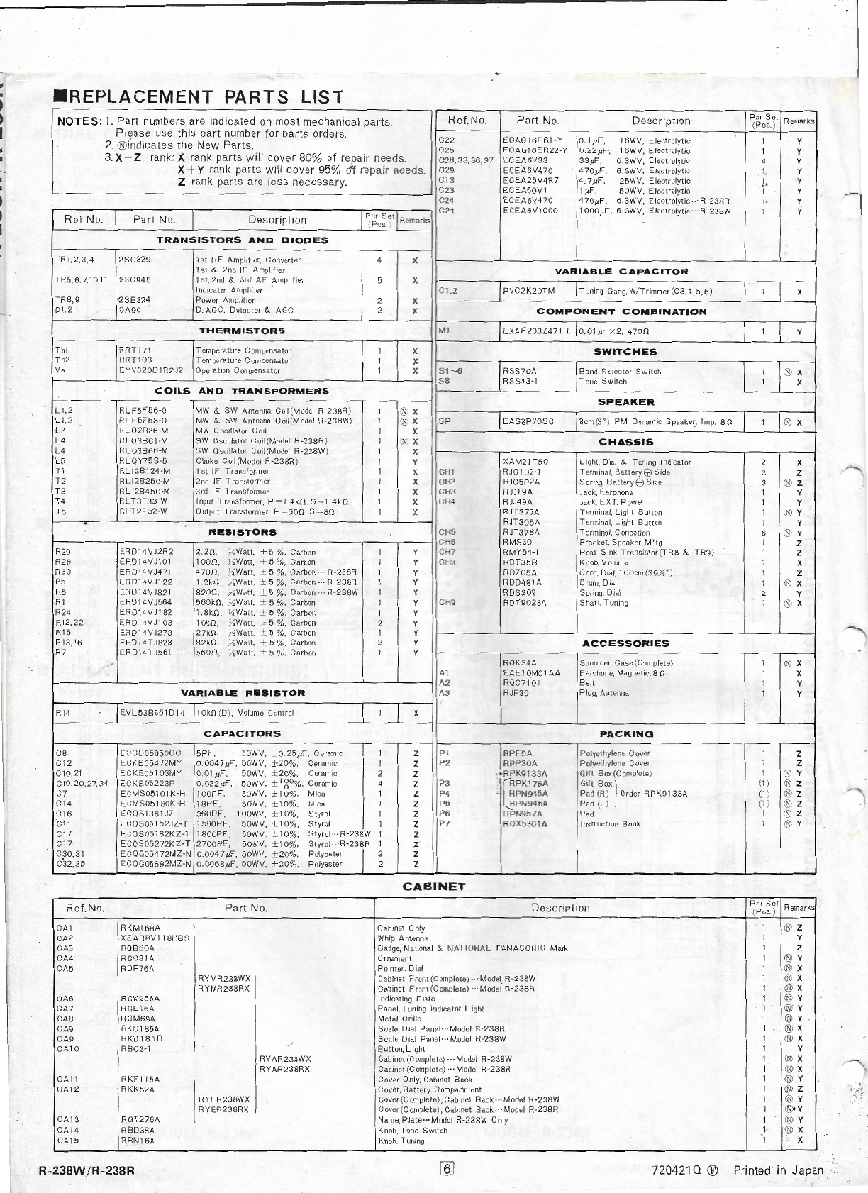
•REPLACEME
NT PARTS LIST
NOTES:
1.
Par
t
numb
ers are indicat
ed
on
most
me
c
ha
nical
pa
rts. Ref.No.
Part
No. Description Per
Se
t Remarks
(P
cs.
)
Pl
ease u
se
this
pa
rt num
be
r for
pa
rt
s or
de
rs.
C22
ECAG1 6ER1-Y
O.
lµ
F, 16WV, E lectrolytic 1 y
2. ®
in
dic
at
es
th
e N
ew
Parts.
C25
ECAGI
6ER22-Y
0.
2
2µ
F
-,
16WV, Elec
tr
olytic 1 y
3.X - Z rank: X rank parts wi
ll
c
ov
er 80% of repair needs. C
28.33
,
36.37
ECEA6V33
33
µF
, 6.3WV.
El
ectrolytic 4 y
X+ Y r
an
k par
ts
will cover 95% of repair need
s.
C29 ECEA6V
470
4
70µF,
6.3W
V,
E
!ec
t
roly
t
ic
1_
y
Z rank
pa
r
ts
are less necessar
y.
Cl
3
ECEA
25V4R7 4
.7µ
F,
25WV,
El
ectrolytic 1 y
C23 E
CEA5
0V1 I
µF,
5
0W
V, Elec
tr
olytic 1 y
C24 E
CEA6V
4
70
4
70µ
F,
6.3WV,
Electrolyt
ic
··R-
238R
]. y
Per S et C24 EC
EA
6
Vl
000 1OOO
µF
, 6.3W
V,
Elec
tr
olytic··· R-23
8W
1 y
Re
f.N
o.
Part
No. Description (Pcs. Reirar-s 1
TRANS
I
STORS
AND
DIODES
TR1,2,3,4 2SC8 29
1st
RF
Amplifier, Converter 4 x
1st
& 2nd
IF
Amplifier
VARIABLE
CAPACITOR
TR5
.6, 7,10, 11
2SC9
45
1st.
2nd &
3r
d AF Amplifier 5 x
I
nd1cator
Amplifier
Cl.
2
PVC2K
20
TM
T
uning
Gang,
W/
Tr
immer
(
C3,4,
5,6) 1 x
TR8
,9
•2SB324
Powe
r Amplifier 2 x
Dl,2
OA90
0 .
AGC
, Detector & A
GC
2 x
COMPONENT
COMBINATION
THERMISTORS
I'.' I EXAF
203Z
4
71
R
0.01µF
X
2,
470!1 1 y
Th! ·
RRT
1
71
Tempe
ra
ture Compensator 1 x I
SWITCHES
Th2
RR
Tl 03 Temperature Compensator 1 x
Va
EYV3
20DI R2J2
Opera
t
ion
Compensator 1 x
Sl
-6
RSS70A Band Selector
Switch
1 ® X
RSS43
-1 Tone Switch 1 x
COILS
AND
TRANSFORMERS
I
SPEAKER
L 1.2 R
LF
5F
56-
0 MW &
SW
Antenna Coil(M
ode
l R-238R) 1
~
x
L 1,2
RLF5
F
58
-0 MW &
SW
Antenna Coil(Model R-238W) 1
~
x " EA
S8P70S
C
Som
(3") PM
Dy
na
mic
S
pea
k
e~.
I
mp.
8!l
1
<SJ
x
L3
RL
02
B
86-
M MW Oscillator
Coil
1 x
L4
RL03B61
-M
SW
Oscillator Coil (Model R-238R) 1
~
x
CHASSIS
L4
RL
03B66
-M
SW
Oscillator Coil (Model R-238W) 1 x
L5
RLQY75S
-5 Choke Coil (Mo
del
R-238R) 1 y XAM21 T
50
light.
Di
a! & Tuning Indicator 2 x
T1
R
L/2
8
124-M
1st
IF
Transformer 1 x C- 1
RJCl
02-1 T
erm
i
nal,
Battery
EE,
Side 3 z
T2
R
L/
28250
-M 2nd
IF
Transformer I x c 2 RJC502A Spr
ing,
Battery8 S
ide
3 @ z
T3
RLl2B450-M
3rd
IF
Transformer 1 x C- 3
RJ
J
19A
Jack,
Earphone 1 y
T4 RL
T3F33-W
Input Transformer, P = 1
.4k0:
S-1.4
k0 I x C
i-..;.
RJJ49A
Jack,
EX
T.
Power 1 y
T5
RLT2F32
-W
Output
Transformer. P
=-
60!1
:
s~so
I x
RJT377A
Termi
nal,
Light Button 1 ® Y
-
RJT30
5A
Ter
mina
l, l
ight
Button 1 y
RESISTORS
c
~;;
RJT378A
Terminal, Conecti
on
6 @ Y
C- 6 RMS30 8 racket, Speak
er
M '
tg
1 z
R29
ERDl
4VJ2R2
2.2!l
.
Y.l'
Watt.
±
5%.
Carbon 1 y C- 7
RMY54
-I
Heat
Smk,
Tr
a
ns
istor (
TR8
& TR9) 1 z
R26
ERDI
4VJ101
IOO!l
,
J..i
Watt,
±5%
, C
ar
bon
1 y c- RB
T3
5B
Knob
, Volume 1 x
R30
ERDl
4VJ471
4700,
){
Watt,
± 5
%,
Carbon ··· R-
238R
1 y
RDZ05A
Cord,
Di
a
l.
I
OO
cm(
39
Ys
") 1 z
R5
ERD14VJ
l2
2 1.
2k!l
,
){
Watt, ± 5
%,
C
ar
bon
··· R-238R 1 y RDD4 81A
Drum.
Dial 1 @ x
R5
ERD14V
J821
8200,
}:j'
Watt, ± 5
%,
Carbon
··· R-238W I y
RDS30
9
Sp
r
ing,
Di
al
2 y
Rl
ERD1 4VJ564 56
0k
!l,
Y.
Watt, ± 5
%.
C
ar
bon
1 y C- 9 RD
T90
2
8A
Shaft, Tuning 1
<S
x
R24
ERD14VJ182
1.8k0,
}{
Watt,
_l_
5
%,
Carbon
1 y
R1
2,
22
ERD14VJ
103 1Ok!l. XWatt, ± 5
%,
C
ar
bon
2 y
R15 ERD1 4
VJ273
27k!l
, XWatt,
J_
5
%,
Carbon 1 y
R1
3,
16
ER
D1
4
TJ823
82k0 ,
){
Watt, + 5
%,
Car
bon
2 y
ACCESSORIES
R7
ERD14
TJ561 56
00.
Y.I
Watt, ± 5
%.
Carbon 1 y
ROK34A
Shoulder Case (Complete) 1
<SJ
x
Al EA
El
OM01
AA Ea
rphone,
M
agn
etic, 8 fl 1 x
A2 ROC7101 Belt 1 y
VARIABLE
RESISTOR
A3 R
JP39
P l
ug,
Antenna 1 y
R14
EVL53B851D
14 1
Ok!l
(D), Volume Control 1 x
CAPACITORS
PACKING
cs ECC
D05050CC
5P
F, 50WV, ±
0.25
µ
F,
Cer
amic
1 z Pl I RPF
5A
P
ol
yethyle
ne
Cover 1 z
C12
ECKE05
472
MY
0.004
7
µF,
50WV, ±
20%,
Ceramic 1 z
P2
RPP30A
P
oly
et
hyl
e
ne
Cover 1 z
Cl0,21
ECKE05103MY
0.01 µF, 50WV, ±
20%.
Ceramic 2 z - • P 9 133A Gi
ft
Box(Complete) 1 @ Y
C1
9,20,
27,34
ECKE05223P
0.0
2
2µF.
50WV.
J:
1g0
%,
Ceramic
4 z P3 < p 1
76A
Gift
Box f (1)
<S:
z
C7 ECMS05101 K-H 1
00P
F,
50WV, ±
10%
. Mica 1 z P4
~::i,g45A
Pad (R) Order R
PK9133A
(1)
:S>
z
C1
4
ECMS05180K-H
18PF,
50WV, ± 1
0%,
Mica 1 z P5
'--._
°'"
946A
Pad (L ) (I )
()9
z
C16
ECQS1361 JZ
360P
F, IOOWV, ±
10%,
Sty
ro
l 1 z P6
::J>
=i
95
7
Pad
1
<S
z
C11
ECOS05152JZ-T
1500PF,
50WV, ± 1
0%.
Styrol 1 z P7 R
536
1A Instructi
on
8
ook
I
<;,
; y
C17
ECOS05182KZ
-T
1800PF,
50WV, ±
10%
. Styrol ·· R-238W 1 z
C17
ECOS05272KZ-T
270
0
PF
, 50WV, ±
10%,
Styrol· ·R
-238R
1 z
C,30,31
ECQG05472M
Z
-N
0.0047µ
F, 50WV, ± 20%, Po
ly
es
ter
I 2 z
C32,35
ECOG05682MZ-N
0.0
068µF
, 50WV, ±
20%.
Polyester 2 z
CABINET
Ref.N
o.
Part No. De
scripti
on P
er
Set
Rem
a
rks
(P
cs.
)
CA1
RKM
1
68A
Cabinet Only 1 @ z
CA2
XEAR
B
Vl
1SHBS
Whip
Antenna
1 y
CA3
RGBBOA Badge, Nat
ional
&
NA
T
IO
AL PANASONI C M
ar
k 1 z
CA4 RGC31 A Ornament I ® y
CA5
RD
P
76A
Po
inter, 0
ia/
1
<SJ
x
RYMR238WX
Ca~inet
Front (C
ompl
e
te
)··· Mode
l.
R-238W 1 ® x
RYMR238RX
Cab
in
et
Front (
Compl
ete) ... Model R-238R 1 ® x
CA6 RGK25
6A
I
nd
icating Plate 1 @ Y
CA7
RGL
I 6A Panel, T
uning
Indicator
light
I @ Y
CAB RGM69A Metal Grille 1
<SJ
y
CA9 RKDI
85A
Seate, 0
ia
l Panel· ·Model R-238R 1 @ x
CA9
R
KD185B
Scal
e,
Dial Panel ··Model R-238W 1 @ X
CA 10 R
BC3
-1
./
Button, L
ight
1 y
RYA
R238WX Cabinet(Complete) ···Model R-238W I @ X
RYAR238RX Cabinet (Complete) ·· ·M
odel
R-238R 1
<SJ
x
CA11
RKF115A
Cover Only, Cabinet Back 1 @ Y
CA12 RKK52A Cover, Battery
Compartm
en
t 1 ® Z
RYFR238WX
Cover (Complete), Cabinet Back· ·Mo
del
R-23
8W
1
<SJ
y
RYE
R238RX Cover (Comµlete), Cabinet Back··· M
ode
l R-
238R
1
·
~
·
Y
CA13
RG
T
276A
Nam
e, Plat
e"'
Model
R-23
8W
On
ly 1
<SJ
y
CA1
4 RBD38A Knob, Tone
Sw
itch 1 @ X
CA1
5
RBN16A
Knob
,
Tuning
1 x
R-238W
/R-238R
720421 Q ® Printed
in
Japan
_